TESTO 400 Instruction Manual
Universal iaq instrument
Hide thumbs
Also See for 400:
- Instruction manual (68 pages) ,
- Short instructions (22 pages) ,
- Instructions (2 pages)
Table of Contents
Advertisement
Quick Links
Advertisement
Table of Contents

Related Manuals for TESTO 400


Summary of Contents for TESTO 400
- Page 1 400 - Universal IAQ instrument Instruction manual...
-
Page 3: Table Of Contents
Setting up an e-mail account ..................20 8.4.6 Tutorial ........................ 20 Connecting probes ....................20 8.6.1 Connecting a cable probe to the testo 400 ..............20 Connecting a Bluetooth ® probe to the testo 400 ............21 8.6.2 Probe update ......................22... - Page 4 Contents Operation .................... 24 Display – user interface ..................24 Main menu ......................25 Preparing for measurement ................26 9.3.1 General measurement information ................26 Measuring mode ......................27 9.3.2 Punctual measurement ....................... 27 9.3.2.1 Continuous measurement ....................29 9.3.2.2 Application menus ....................
- Page 5 Measurement settings ....................94 Company details ......................95 10.3.4 Torch .......................... 95 10.3.5 10.3.6 Display settings ......................96 Resetting the testo 400 to factory settings ..............97 10.3.7 General information .................... 97 10.4 General instrument information .................. 97 10.4.1 10.4.2 Calling up the tutorial ....................
- Page 6 Contents 13.5 Launching testo DataControl ................104 Connecting the testo 400 .................. 104 13.6 Customer management ..................107 13.7 Creating and editing customers and measuring sites ..........107 13.7.1 13.7.1.1 Customer .......................... 107 Measuring site ........................108 13.7.1.2 Search function ......................111 13.7.2...
-
Page 7: About This Document
Pay particular attention to the safety instructions and warning advice in order to prevent injury and damage to the product. 2 Safety and disposal Take the testo information document into account (accompanies the product). 3 Product-specific approvals You can find the current country approvals in the Approval and Certification document (enclosed with the product). -
Page 8: Data Protection
5 Data protection 5 Data protection The testo 400 measuring instrument makes it possible to input and store personal data such as name, company, customer number, address, telephone number, e-mail address and homepage. Please be aware that your use of the functions offered here is entirely your own responsibility. -
Page 9: Product Description
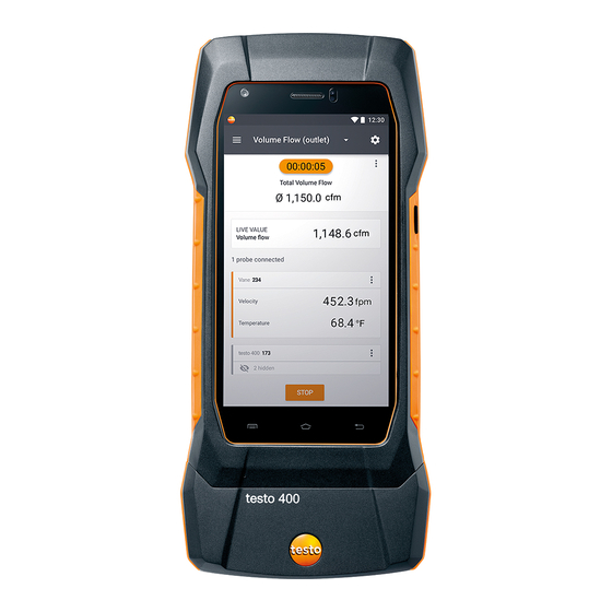
7 Product description 7 Product description Front view 1 On/Off and Standby button 2 User interface/Touchscreen (see Section 9.1) 3 Front camera 4 Connections for probes (see Section 7.3) -
Page 10: Rear View
7 Product description Rear view 1 Camera 2 Differential pressure measurement connections (+/- marking) 3 Magnets 4 Attachment point for carrying strap 5 USB port/mains connection CAUTION Make sure the pressure tube does not jump away from the connection socket. Risk of injury! - Ensure correct connection. -
Page 11: Probe Overview
7 Product description 1 Thermocouple probe type K 2 Connection for probes with connection (T1 and T2) TUC connector (A and B) Probe overview Compatible cable probes (digital) 7.4.1 Description Order no. Hot wire probe, fixed cable, including temperature 0635 1032 sensor Hot wire probe, fixed cable, including temperature and 0635 1572... -
Page 12: Compatible Ntc Probes (Analog)
(Duran 50), resistant to aggressive media Compatible Smart Probes (digital) 7.4.5 Description Order no. testo 115i - clamp thermometer operated by smartphone 0560 1115 0560 2115 02 0560 2115 03 (US) testo 805i - infrared thermometer operated by 0560 1805... -
Page 13: Compatible Type K Thermocouples (Analog)
0560 2605 02 0560 2605 03 (US) testo 405i - thermal anemometer operated by 0560 1405 smartphone testo 410i - vane anemometer operated by smartphone 0560 1410 testo 510i - differential pressure measuring instrument 0560 1510 operated by smartphone testo 549i - high-pressure measuring instrument... -
Page 14: Commissioning
Charging the energy storage unit 8.1.1 Connect the USB mains unit to the USB interface/mains unit socket of the testo 400 (see Section 7.2). Connect the mains plug of the mains unit to a mains socket. The charging process starts. - Page 15 8 Commissioning down.” The instrument should only be switched back on after a brief charging phase. The minimum battery level must be 6%.
-
Page 16: Rechargeable Battery Led Status
400 (see Section 7.2). Connect the mains plug of the mains unit to a mains socket. The measuring instrument is powered via the mains unit. The battery charges. Switching the testo 400 on and off Current Action Function status... - Page 17 8 Commissioning Current Action Function status When the measuring instrument is started for the first time, the setup wizard guides you through the following setting parameters step by step: Language Country Units WLAN Date and time Own company address E-mail account After the setup wizard, a tutorial can be launched.
-
Page 18: Touchscreen
Setup wizard When the testo 400 is started up for the first time, the setup wizard is activated and guides you step-by-step through the following setting parameters. The instrument setup that is implemented can be adapted at any time in Settings menu. -
Page 19: Country Settings And Units
PDF reports at the top right of the document and also listed in the measurement data report. The company details stored in the testo 400 at the time of the measurement cannot be subsequently changed in the PDF report... -
Page 20: Setting Up An E-Mail Account
Connecting a cable probe to the testo 400 8.6.1 > Connect the testo 400 to the probe via the TUC slot. The cable probe is immediately displayed in the sensor management, in the basic view and in the relevant measurement menu. -
Page 21: Connecting A Bluetooth ® Probe To The Testo 400
8.6.2 The Bluetooth ® connection from the testo 400 for the probes is always activated and cannot be switched on and off manually. It is established automatically, and no special pairing is required. Switch on the probe using the button on the Bluetooth ®... -
Page 22: Probe Update
8 Commissioning Probe update 8.6.3 If the probe does not have the latest firmware, an update notification appears (this requires activation of the relevant switch in the Instrument information menu (Section 10.1 / 10.4.1). This is only possible for cable probes, but you can also connect and update other probe heads with the cable handle. - Page 23 8 Commissioning Update status.
-
Page 24: Operation
9 Operation 9 Operation Display – user interface Open main menu Display of the measurement period Display of calculated measurement results Reading for each probe Can be controlled with different function keys Instrument status bar Configuration Edit reading display Further symbols on the user interface (without numbering) One level back Exit view Share report... -
Page 25: Main Menu
(see Section 9.7) Settings (see Section 10) Help and Information (see Section 10.4) Other applications (see Section 10.4.5) Additional icons on the testo 400: One level back Delete Exit view Further information Share measurement data/reports Display report Search Edit Favourite... -
Page 26: Preparing For Measurement
60 sec > 1 day to 21 days 5 min With the testo 400 (and the IAQ data logger), a maximum 1 million readings (with a maximum of 18 channels) can be recorded with one measurement. Example 1: Result: 9,216 readings... -
Page 27: Measuring Mode
9 Operation If a probe’s individual readings are hidden, these settings are stored on the testo 400 specifically for each probe and applied to all application menus. Whereas the units set are only stored in the corresponding application menu, but are time-independent. - Page 28 New: launch a new measurement. The current measurement will be deleted along with all readings (a warning is displayed). Save: exit the current measurement and save all readings on the testo 400 (see Section 9.6).
-
Page 29: Continuous Measurement
9 Operation 9.3.2.2 Continuous measurement For the continuous measurement, a start time, a measurement duration and a measuring cycle can be defined or the measurement can be started and finished manually. Click on Apply Configuration to start the measurement (with a scheduled start time). - Page 30 (a warning is displayed). Save: exit the current measurement and save all readings on the testo 400 (see section 9.6). The counter in the upper section turns orange and measures the time (after stopping, the counter turns grey again). To the left of the counter, the number of the current/last measurement is displayed (e.g.
-
Page 31: Application Menus
9 Operation Application menus The testo 400 has permanently installed measurement programs. These enable the user to carry out convenient configuration and implementation of specific measuring tasks. Measurement menus: The testo 400 offers the following Basic view Volume flow, duct Volume flow rate –... -
Page 32: Basic View
The measuring mode can be selected via the Configuration menu (see Section 9.4.2). All probes that can be connected to the testo 400 are also displayed in the Basic view application menu. As this is not an application menu where only specific probes can be used, all probes are highlighted in orange on the left- hand side. -
Page 33: Volume Flow, Duct
9 Operation Table view 9.4.1.2 Open the main menu 2 Change of display 3 Column with date and time 4 Arrow keys to go directly to the end of the table 5 Status bar Open the configuration menu 7 Probe ID - measurement unit 8 Measuring values 9 New / Start / Stop /... - Page 34 9 Operation Click on Configuration menu opens. Make the required settings. The measurement can be started even without customer data. This can be added following the measurement result.
- Page 35 9 Operation Make further settings accordingly. Click on Apply Configuration. Values currently being measured are displayed.
-
Page 36: Volume Flow Rate - Grid Measurement As Per Din En 12599
9 Operation Volume flow rate - grid measurement as per 9.4.3 DIN EN 12599 With this application, the volume flow in a ventilation system duct can be measured as per the DIN EN 12599 standard. There are various options for this, which differ mainly in terms of the measuring range and the required probes: •... - Page 37 9 Operation Make the required settings and click on Next. For volume flow measurement as per the DIN EN 12599 standard, it is necessary for the measurement to be carried out at different measuring points. The number of measuring points depends on the distance from the point of discontinuity and irregularities in the profile.
- Page 38 9 Operation Following successful measurement of a measuring point, the measurement assistant jumps straight to the next measuring point until all the measuring points are marked with a tick. You now have three options to proceed. It is also possible to correct and overwrite individual measuring points by selecting the corresponding point on the display and starting a new measurement.
- Page 39 (a warning is displayed). Save: exit the current measurement and save all readings on the testo 400 (see Section 9.6). If large differences in flow velocities are ascertained over the cross- section, the number of measuring points must be increased. The number of measuring points is then adequate if the measurement value for each area is representative for its immediate surroundings, i.e.
-
Page 40: Volume Flow Rate - Grid Measurement As Per Ashrae 111
9 Operation At the end of a volume flow measurement in compliance with the standards, the average volume flows are shown on the results display, along with the information about measuring accuracy, which helps to better estimate the measurement result. - Page 41 9 Operation Click on Main menu opens Click on Measure. Click on Volume flow rate - grid measurement as per ASHRAE 111. The Volume flow rate - grid measurement as per ASHRAE 111 measurement menu opens. Click on ...
- Page 42 9 Operation Click on Start. The longer a measuring point is measured, the more accurate the result at the end of the volume flow measurement as per DIN EN 12599. During the measurement in the duct, the required immersion depth of the next measuring point is automatically shown on the display.
-
Page 43: Volume Flow, Outlet
(a warning is displayed). Save: exit the current measurement and save all readings on the testo 400 (see Section 9.6). If large differences in flow velocities are ascertained over the cross- section, the number of measuring points must be increased. The number of measuring points is then adequate if the measurement value for each area is representative for its immediate surroundings, i.e. -
Page 44: Volume Flow - Funnel
9 Operation Click on Configuration menu opens. Make the required settings. When measuring the volume flow at outlets, it is possible to enter the free area of the outlet as a percentage in order to take possible sources of interference into account. Click on Apply Configuration. - Page 45 Apply: the current reading is applied. New: launch a new measurement. The current measurement will be deleted along with all readings (a warning is displayed). Save: exit the current measurement and save all readings on the testo 400 (see Section 9.6).
-
Page 46: Volume Flow, Pitot Tube
9 Operation Volume flow, Pitot tube 9.4.7 Use this application to measure the volume flow in a ventilation system duct. The Pitot volume flow measurement is suitable for high velocities and flows with a high particle content. Click on Main menu opens Click on Measure. - Page 47 9 Operation Make further settings accordingly. Prandtl Pitot tubes (order no.: 0635 2045, 0635 2145, 0635 2345): Pitot tube factor: 1.00. Straight Pitot tubes (order no.: 0635 2043, 0635 2143, 0635 2243): Pitot tube factor: 0.67. For Pitot tubes from other manufacturers, please refer to the instruction manual for the Pitot tube factor or ask your supplier.
- Page 48 9 Operation Click on to zero the differential pressure sensor. A message is displayed, the pressure is zeroed. Click on Start. The measurement starts.
-
Page 49: Volume Flow - K-Factor
9.4.8 The testo 400 can determine the volume flow by measuring the reference resistance and input of the K-factor. This allows the testo 400 to remain connected to the air outlet during adjustment work and the changes in volume flow can be read directly on the display. - Page 50 9 Operation Click on Configuration menu opens. Make the required settings. Apply Configuration. Click on Click on Start. The measurement starts.
-
Page 51: Comfort Level - Pmv / Ppd (En 7730 / Ashrae 55)
New: launch a new measurement. The current measurement will be deleted along with all readings (a warning is displayed). Save: exit the current measurement and save all readings on the testo 400 (see Section 9.6). Comfort level – PMV / PPD (EN 7730 / 9.4.9... - Page 52 9 Operation Click on Main menu opens Click on Measure. Click on Comfort level – PMV/PPD. The Comfort level – PMV/PPD measurement menu opens. Click on Configuration menu opens. Make the required settings. Clothing and Activity. Determine...
- Page 53 9 Operation Click on Apply Configuration. Values currently being measured are displayed. Values currently being measured are displayed graphically. Factors to be entered...
- Page 54 9 Operation Clothing Clothing reduces body heat losses and is therefore classified based on its insulating value. The insulating effect of clothing is given in the unit clo or m² K/W (1 clo = 0.155 m² K/W). The clo value can be calculated by adding together the values of the individual items of clothing.
-
Page 55: Discomfort - Draught Rate
DIN EN 13779 and DIN EN 7730, as well as ASHRAE 55. The draught rate measures the air temperature, fluctuation and standard deviation of the air velocity. From these three values, the testo 400 calculates the percentage of dissatisfaction due to draughts. - Page 56 9 Operation The turbulence probe requires a warm-up period of around 3 seconds after connection to the testo 400. Carry out the measurement after this. For unimpaired measurement, we recommend attaching the probe(s) to a tripod. In combination with the testo tripod and the IAQ data logger, up to 3 probes can be positioned at the relevant heights in accordance with the standards.
- Page 57 9 Operation Make the required settings. Click on Apply Configuration. Using the 3-digit probe ID, assign the probes to the respective measuring position. It is possible to connect up to three probes simultaneously (with IAQ data loggers), but also to measure with one probe at three heights in succession.
-
Page 58: Differential Temperature (Δt)
9 Operation Values currently being measured are displayed. The measuring values can also be called up in the Graphic Table views. If the heights are being measured one after the other, you can click directly on the second height following successful measurement of the first height, and only after completion of the third height can the measurement be saved. - Page 59 9 Operation Click on Main menu opens Click on Measure. Click on Differential temperature (ΔT). Differential temperature (ΔT) measurement menu opens. Click on Configuration menu opens. Make the required settings. Apply Configuration. Click on Click on Start. ...
-
Page 60: Differential Pressure (Δp)
Values currently being measured are displayed. 9.4.12 Differential pressure (ΔP) The testo 400 has an internal absolute and differential pressure sensor. This sensor can be used, for example, to investigate the differential pressure of two rooms. Connect the pressure tubes to the + and - connection sockets. - Page 61 9 Operation Click on Configuration menu opens. Make the required settings. Apply Configuration. Click on Click on to zero the differential pressure sensor. Click on Start. The measurement starts. Values currently being measured are displayed.
-
Page 62: Customer Management
9 Operation If the readings fluctuate wildly, it is advisable to damp the readings (see Section 9.7.5). Customer management In the Customer menu, all customer and measuring site information can be created, edited and deleted. Fields marked with * are mandatory. Without any information in this field, no customers or measuring sites can be stored. -
Page 63: Creating And Editing Measuring Sites
9 Operation Creating and editing measuring sites 9.5.2 Click on Main menu opens Click on Customer. The Customer menu opens. + New customer. Click on Click on right tab Measuring site. Click on + New measuring site. A new measuring site can be created. -
Page 64: Duct Measuring Site
9 Operation For the duct, outlet or duct with k-factor measuring sites, further parameter settings can be implemented. Click on Save. The new measuring site has been saved. Duct measuring site 9.5.2.1 Click on Duct. Other characteristics are displayed. Input the characteristics accordingly: Duct geometry, air type, duct dimensions (different measurement units can be selected) and correction factor. - Page 65 9 Operation Due to pressure drops in the system, the measured volume flow may be smaller than the actual volume flow. The measured volume flow can be corrected via the flow rate correction factor. The flow rate correction factor has a directly proportional effect on the measurement result and is usually set at 1.00.
-
Page 66: Outlet Measuring Site
9 Operation Outlet measuring site 9.5.2.2 Click on Outlet. Other characteristics are displayed. Input the characteristics accordingly: Duct geometry, air type, duct dimensions (different measurement units can be selected) and correction factor. The correction factor is preset to 1.0 by default. The setting can be between 0.01 and 9.99. -
Page 67: K-Factor Measuring Site
9 Operation k-factor measuring site 9.5.2.3 Click on k-factor. Other characteristics are displayed. Enter the relevant characteristics: specific k-factor, volume flow, differential pressure and air type. Click on Save. Settings have been saved. -
Page 68: Searching For And Managing Customers And Measuring Sites
9 Operation Searching for and managing customers and 9.5.3 measuring sites Searching for a customer Click on Main menu opens. Click on Customer. The Customer menu opens. Click on The input window appears. Enter the name. The selected customer appears in the overview. - Page 69 9 Operation Click on The input window appears. Enter the name. The selected customer appears in the overview. Click on the Measuring site tab. The Measuring site menu opens. Click on The input window appears. Enter the name. ...
-
Page 70: Measurement Data Management
Measurement data management Memory. You All measurements stored on the testo 400 can be found in the can store customer and measuring site information, add images and comments, create PDF reports, CSV and JSON data, and export via Bluetooth or e-mail. -
Page 71: Managing Measurement Data
9 Operation Managing measurement data 9.6.1 After clicking on a saved measurement, the corresponding results screen is displayed. All properties for the measurement are listed there. Customer and measuring site information can be stored, images and comments can be added and PDF reports, CSV and JSON data can be created and exported via Bluetooth or e-mail. - Page 72 9 Operation If required, Write comment, up to 1000 characters. The customer, the attached images and the comments are displayed in the results view. The calculated result of the measurement is displayed under the Customer data, Images and Comments.
- Page 73 PMV/PPD measurements. The graphic progression of the individual measurements can be called up at any time in the testo DataControl software (see Section 13.8.2). For HVAC grid measurements in accordance with EN 12599 or ASHRAE, the gauged Measuring Points and not the measuring values are listed generally.
- Page 74 9 Operation CSV file JSON file Start export. If necessary, Select and click on activate the Add Attach Images button. Export options are displayed. Click on Bluetooth or E-mail. An e-mail account must be set up before this option can be used (see Section 10.2).
- Page 75 Create PDF with all readings is only possible up to 30 pages in the testo 400, due to the resulting file size and number of pages. In the testo DataControl software, however, PDF reports can be created for all measurements without any restrictions.
-
Page 76: Editing Measurement Data
9 Operation Editing measurement data 9.6.2 Click on Main menu opens. Click on Memory. The Memory menu opens. Click on Selection fields appear next to each stored measurement. - Page 77 9 Operation Click on the selection fields for the required measurements. The measurements are marked with a tick. Click on Export Report. All marked measurements are sent as CSV or JSON files or as PDF reports via Bluetooth ®...
-
Page 78: Searching For Measurement Data
9 Operation Searching for measurement data 9.6.3 The search function allows you to quickly and easily filter the measurements you are searching for according to certain search terms. Both the customer and measuring site names as well as the descriptions of the applications are included in the search. - Page 79 9 Operation Click on The text box for the search is displayed. The search term can be entered. Upper and lower case letters do not have to be taken into account when entering text.
-
Page 80: Sensor Management
9 Operation Sensor management All sensors that the testo 400 uses can be found in the Sensors menu. There, you can view general information about currently connected probes as well as recently connected probes. In addition, you can enter and call up calibration information, activate damping and carry out adjustment and humidity calibration. -
Page 81: Calibration
9 Operation Calibration 9.7.2 For all sensors, calibration data can be stored under the Measurement parameter tab for individual measurement parameters. The probe is connected to the testo 400. Click on Main menu opens. Click on Sensors. ... -
Page 82: Surface Increment
(or the reverse if the surface is colder than the environment). This effect can be corrected by an increment in % of the reading. The probe is connected to the testo 400. Click on ... -
Page 83: Adjustment
This technology means that measurement uncertainty caused by the instrument is no longer an issue. The probe can be calibrated without a handheld instrument. Entering the adjustment/calibration data generates a zero-error display. The probe is connected to the testo 400. Click on ... - Page 84 9 Operation Click on the required measurement parameters. The measurement parameter opens. Click on Adjustment. A total of six different adjustment values can be stored. Input Current, Target SH and the Unit. Click on Adjust. The adjustment data entered can be deleted at any time in the sensor management via the icon.
-
Page 85: Damping
9 Operation Damping 9.7.5 If the readings fluctuate wildly, it is advisable to damp the readings. The probe is connected to the testo 400. Click on Main menu opens. Click on Sensors. The Sensors menu opens. Click on the required sensor. -
Page 86: Humidity Calibration
11.3 %RH and 75.3 %RH; any measuring value deviations from the nominal value are minimized across the entire measuring range. The Testo calibration set provides a reference value to calculate the offset for a humidity calibration. Humidity calibration is possible with the following probes: Order no. - Page 87 9 Operation Click on Start Adjustment. Humidity calibration is started.
-
Page 88: Settings
10 Settings 10 Settings 10.1 Carrying out a testo 400 update If a new update is available, an orange dot appears in the main menu at Help, information. This notification only appears if there is a WLAN connection. Otherwise, it is not possible to check whether updates are available. - Page 89 Later to do this at a later date. If a cable probe with older firmware is connected to the testo 400, the probe can be updated or removed (see Section 8.6.3). We always recommend carrying out the probe update, since the introduction of new firmware always serves a purpose or solves an existing problem on the market.
-
Page 90: Setting Up An E-Mail Account
If an Exchange e-mail account is set up, a request for the PIN code entry or a password will be made for security reasons. From now on, this PIN code or the password will be required each time you unlock the screen. For security reasons, resetting is only possible via testo Service. -
Page 91: Deleting An E-Mail Account
Many e-mail providers have security systems that prohibit signing up to the e- mail app on the testo 400. This is why setting up an e-mail account generally works best via the IMAP and SMTP incoming and outgoing servers. -
Page 92: Making Basic Settings
10 Settings 10.3 Making basic settings Basic settings contains all the general settings for the testo 400. Configurations implemented in the Setup wizard can be changed here. 10.3.1 Regional settings Click on Main menu opens. Click on Settings. ... -
Page 93: Wlan & E-Mail
10 Settings Click on Country. Information window is displayed. Click on OK. Select Country. Click on Time. Information window is displayed. Click on OK. Set the Date & Time. 10.3.2 WLAN & e-mail Click on Main menu opens. Click on Settings. -
Page 94: Measurement Settings
10 Settings Select WLAN network. Click on E-mail. Account setup appears. You can set up your account in just a few steps. Follow the instructions. E-mail accounts. Click on Window with warning opens. Remove accounts or Cancel. Click on 10.3.3 Measurement settings Click on ... -
Page 95: Company Details
10 Settings 10.3.4 Company details Click on Main menu opens. Click on Settings. Settings menu opens. Click on Company details. Company details menu opens. Click on required fields. Enter information. 10.3.5 Torch Click on Main menu opens. Click on Settings. -
Page 96: Display Settings
10 Settings 10.3.6 Display settings Click on Main menu opens. Click on Settings. Settings menu opens. Click on Display Settings. Display Settings menu opens. Display Brightness, move the controller to the left or right. For the The display becomes brighter or darker. -
Page 97: Resetting The Testo 400 To Factory Settings
Cancel. 10.4 General information Under General Information, you will find information about the testo 400, and the tutorial can once again be called up and implemented. There you will also find the Quick Start Guide, the detailed instructions and the legal information. -
Page 98: Calling Up The Tutorial
10 Settings It is possible to check manually whether updates for the app or firmware are currently available. Enable Automatically check for updates with the slider. Click on Check for updates. The system searches for updates. Follow the instructions. Automatic probe update can be enabled or disabled. -
Page 99: Calling Up Legal Information
10 Settings Click on Quickstart Guide Instruction Manual. The Quickstart Guide for the testo 400 including IAQ data logger and the testo DataControl software are displayed in pdf format. 10.4.4 Calling up legal information Click on Main menu opens. -
Page 100: Maintenance
This means that both export options will be available again in the future. 11 Maintenance 11.1 Rechargeable battery care Battery replacement may only be carried out by Testo Service. • At low ambient temperatures, rechargeable battery performance decreases. This reduces the available useful life. -
Page 101: Technical Data
12 Technical data General Feature Value Probe connections - 2x type K thermocouple - 2x Testo Universal Connector (TUC) for connecting cable probes to the corresponding plug - 1x differential pressure - 1x absolute pressure (integrated) - 4x Bluetooth ®... -
Page 102: Testo Datacontrol Pc Software
13 testo DataControl PC software 13.1 General information The testo 400 has a USB port, via which the measuring instrument can be connected to the PC. Knowledge of Windows ® operating systems is required to work with the software. -
Page 103: System Requirements
Download testo DataControl software (www.testo.com/download- center) Launch the DataControl.exe file. Follow the instructions of the installation wizard. Click on Finish to complete the software installation. Use the USB cable to connect the testo 400 to the PC. The connection will be established. -
Page 104: Launching Testo Datacontrol
(double-click on left mouse button). testo DataControl launches automatically. 13.6 Connecting the testo 400 As long as the testo 400 is not connected to the computer, No Instrument found is displayed at bottom left. All customers are listed in... - Page 105 13 testo DataControl PC software As soon as the testo 400 is connected via a USB cable to a computer, Connected to testo 400 – Synchronizing is displayed at bottom left. A message about data transfer is displayed. Confirm by pressing to transfer all customer and measurement data from the testo 400 to the software.
- Page 106 400 by clicking the right Moreover, there is the option of transferring customer data and measuring site Customer with measuring information from all customers by simply clicking on sites. If the data transfer to the testo 400 was successful, the icon changes to...
-
Page 107: Customer Management
In the Customer menu, all customer and measuring site information can be created, edited, deleted and transferred to the testo 400. All customer and measuring site information created on the testo 400 is also displayed following successful transfer to the software. -
Page 108: Measuring Site
13 testo DataControl PC software Only the field Company/customer name is mandatory. Other fields may remain blank. Measuring site 13.7.1.2 Search for customer's measuring site Several measuring sites are stored. > Click on Search field opens. Create new measuring site Any number of measuring sites can be created for the selected customer. - Page 109 13 testo DataControl PC software The following measuring site information can be saved and/or changed: Measuring site name System number System type Manufacturer Year of construction System serial number Annotation The following characteristics can be assigned to the respective measuring site:...
- Page 110 13 testo DataControl PC software HVAC grid measurement (optional) Activate HVAC grid measurement using the slider. Additional fields expand. The following data can be stored: Duct geometry, air type, duct dimensions and the correction factor, number of inspection holes and measuring points as well as the inspection hole position and the reference volume flow for the respective measuring site.
-
Page 111: Search Function
13 testo DataControl PC software 13.7.2 Search function Customer menu is open. Click on Search field with customer list opens. Enter customer name in the search field. Customer is displayed. -
Page 112: Delete Function
13 testo DataControl PC software 13.7.3 Delete function Customer menu is open. Click on the required customer (or measuring site). The stored customer plus all measuring site information are deleted. All measurements carried out must be deleted separately in the Memory menu. -
Page 113: Memory Management
Memory menu, you can call up all the measurement results stored with the testo 400 and transferred to the software, analyze them in detail and also create and save csv data and PDF reports. In principle, stored measurements CANNOT be edited. The stored measurement data recorded with the testo 400 cannot be changed. -
Page 114: Graphic View
PDF report on the computer or permanently deleted When creating a PDF report, there is the option, as on the testo 400, to include only the average measuring values or to integrate all measured values in the report. - Page 115 13 testo DataControl PC software Clicking on one of the four channels opens the selection of measurement parameters recorded during the measurement. The measuring parameters can easily be assigned to the individual channels via the probe ID and measuring unit or selected as assigned.
- Page 116 13 testo DataControl PC software The total measurement period in the example in the figure above is 60 minutes. After changing the start time, only the last 10 minutes of the measurement are displayed in the graphic in accordance with the selection. Adjusting the time enables the measuring values to be analyzed in detail.
- Page 117 13 testo DataControl PC software Via the first tab Characteristics and the field Display properties, you can change the clothing and activity parameters in the next window. This recalculates the PMV/PPD values and also the graphic. In order to be able to compare different calculations/graphics with each other, you need to save the respective CSV and PDF files.
- Page 118 For future measurements, the required measurement parameters can be selected in the testo 400 prior to the measurement. (see Section 9.1 - point 8 Edit reading display).
-
Page 119: Searching For And Deleting Measurement Results
13 testo DataControl PC software 13.8.4 Searching for and deleting measurement results In the Memory menu, all stored measurements are sorted by date and time. Memory menu is open. Click on Search field with measurements opens. Enter the customer name or measuring site or date/time in the search field. - Page 120 13 testo DataControl PC software Deleting Click on A check box is displayed in front of each measurement. Click on the required measurement. A tick is displayed in the respective box. Click on Information window is displayed.
- Page 121 13 testo DataControl PC software Assigning measurements Measurements that have not been assigned to a customer/measuring site can be subsequently assigned. > Activate Filter out missing customers slider. All measurements are displayed without customer or measuring site information.
-
Page 122: Settings
13 testo DataControl PC software 13.9 Settings Under Settings, the company details can be saved and the language selected. Settings menu is open. Click on Language. Selection window opens. Select language. Click on Company details. Fill in the following fields:... -
Page 123: Help And Information
Click on the button to call up the brief instructions or complete instruction manual for the testo 400 including IAQ data logger and testo DataControl software as a PDF file. The software licences used by the testo DataControl software are listed under Licence usage. -
Page 124: Iaq Data Logger
14 IAQ data logger 14 IAQ data logger The IAQ data logger is used in conjunction with the testo 400 universal IAQ instrument to carry out long-term measurements of climatic and comfort level conditions independently of the measuring instrument. The IAQ data logger with connected cable probes is configured with the aid of the testo 400 universal IAQ instrument. -
Page 125: Iaq Data Logger Rear View
The IAQ data logger is supplied with a USB mains unit. No recording of measurement data occurs without power supply via the mains unit cable. The Testo USB mains unit has the specification 5V / 2A. CAUTION Power supply via a mains unit cable! Tripping hazard! - Take care when routing the mains unit cable. -
Page 126: Switching The Iaq Data Logger On And Off
To ensure reliable instrument detection on the testo 400, first connect the IAQ data logger to the power via the USB port and then connect it to the testo 400 using the cable attached to the rear. -
Page 127: Measuring With The Iaq Data Logger
In this variant, you set up the IAQ data logger, which carries out the planned measurement with the connected probes. The testo 400 is only required for the pre-settings and can be used elsewhere following successful configuration. -
Page 128: Carrying Out A Measurement With The Iaq Data Logger
14 IAQ data logger 14.6.2 Carrying out a measurement with the IAQ data logger Click on Measure. Measurement programs are displayed. Select the measurement program in conjunction with the IAQ data logger. (Basic view, Comfort level – PMV/PPD or Discomfort - draught rate) ... - Page 129 14 IAQ data logger IAQ Data Logger Enable using the slider. Configure measurement for standalone use.
- Page 130 14 IAQ data logger Click on Apply Configuration. The selected measurement program is displayed. Click on Transfer to IAQ Data logger.
-
Page 131: Reading The Iaq Data Logger
14.7 Reading the IAQ data logger Since the IAQ data logger is a standalone instrument, the testo 400 can be used for other measuring tasks following configuration of the IAQ data logger, while the measurement is ongoing. -
Page 132: With Testo 400 Connected
Disconnect the testo 400 from the IAQ data logger. testo 400 can be used for other measurements. If the testo 400 was connected to the IAQ data logger for the measurement procedure, then the measurement is automatically stored on the measuring instrument. -
Page 133: With The Testo 400 Disconnected
14 IAQ data logger 14.7.2 With the testo 400 disconnected Connect the testo 400 to the IAQ data logger via the TUC connector. Once connected successfully, a message appears on the screen. The measurement data is transmitted. Data transmission may take some time. -
Page 134: Led Status
(rapidly) Flashing red Internal error. Disconnect the mains unit from the power supply and reconnect it after a brief waiting period. If the problem persists, contact Testo Customer Service. 14.9 Technical data for IAQ data loggers Feature Value Probe connections... -
Page 135: Questions And Answers
If the WLAN reception is not sufficient, the error message. message Network disabled appears. Connect the testo 400 to a better WLAN network. When updating, make sure that there is a stable WLAN connection so that the update process does not abort. -
Page 136: Contact And Support
400 + 1x CO2 + 2x TC approx. 9 hours testo 400 is not If the testo 400 is not responding to any gestures, responding. press the On/Off button for about 10 seconds to restart the instrument. 15.1 Contact and support If you have any questions or need further information, please contact your dealer or Testo Customer Service. - Page 138 Testo SE & Co. KGaA Testo-Strasse 1 D-79853 Lenzkirch Germany Phone: +49 7653 681-0 Fax: +49 7653 681-7699 E-mail: info@testo.de www.testo.com 0970 4011 en 01...
Need help?
Do you have a question about the 400 and is the answer not in the manual?
Questions and answers