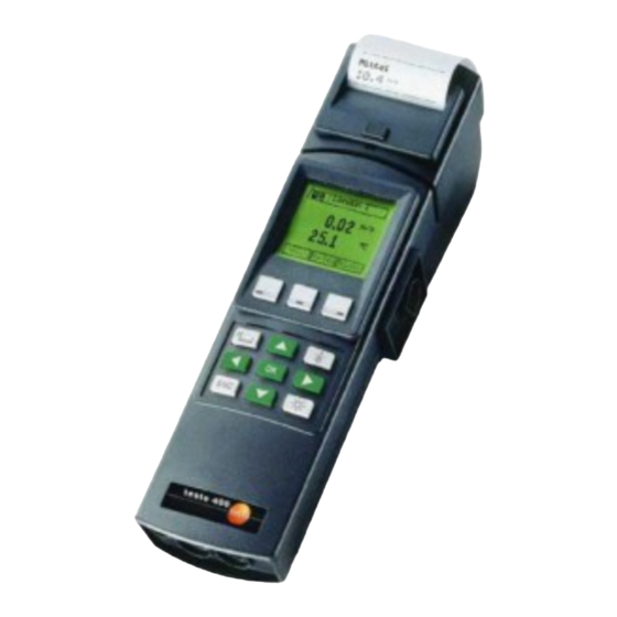
TESTO 400 Instruction Manual
Hide thumbs Also See for 400:

Advertisement

testo 400 · testo 650 · testo 950
Instruction manual
en

Advertisement

Table of Contents
loading
Need help?

Need help?

Do you have a question about the 400 and is the answer not in the manual?

Questions and answers

Summary of Contents for TESTO 400

  • Page 1 400 · testo 650 · testo 950 Instruction manual...
  • Page 2: Table Of Contents

    Update on disk ..........................52 Technical data ...........................53 Ordering data..........................55 Index ...........................64 The conformity certificate confirms that the instruments meet 89/336/EWG guidelines. © 2002 Copyright Testo AG The software and software structure included in the product testo 400 are protected by copyright laws worldwide.
  • Page 3: Introduction

    The instruction manual describes the maximum available range of functions in the testo 400. testo 650 and testo 950 have limited derived functions in relation to the probes which can be connected and the parameters which can be analysed - See table:...
  • Page 4: Initial Operation Of Instrument

    Unscrew the back of the measuring instrument. Place the button cell (Part no.: 0515.0028) in the opened battery compartment with the “+” pole on top and put in the batteries or the Testo rechargeable batteries (Part no. 0554.0196). Observe polarization! Close battery compartment.
  • Page 5 Initial operation of instrument First measurement A quick introduction is provided by the instrument and system descriptions on pages 6-9. This symbol stands for further information . Look for the adequate word in the keyword context, further informations are available on the indicated page. Note: The measuring instrument should be switched off before connecting a probe.
  • Page 6: Description Of Instrument

    Description of instrument * testo Comsoft software, Version Attachment for printer Infrared 3.0 or newer, is required for data interface for exchange with your PC. printer Function box Location Function box: Print/ • Serial interface (RS 232) for connection to PC* Save/ •...
  • Page 7 Description of instrument 5 function fields are set up around the data display which provide information on additional functions during measurement. In order to set up these functions which can be activated directly, leave the measurement window by pressing . The current measurement is then interrupted.
  • Page 8: Function Fields

    System description Function fields MEASURING Lenzkirch 41. 3 25. 1 Main m m enu 11. 1 Target for data when the Print Memory Memory button is Printer Printer Printer pressed Both Both List of measuring Factory hall2 L e n z k i r c h locations Store Cold store...
  • Page 9: Menu Overview Configuration

    Abs. Alt. ODULE aw V barom. Pr. ALUE INSTRUMENT diff. Press. NITS Density OWER DDRESS ROTECTION Display ESET DEFAULT Memory PROM Beeper PRINT NSTR DATA Analog ONFIGURATION attach. Printer RINTER TYPE Testo Printer RINT ARAM LANGUAGE EUTSCH *On request NGLISH...
  • Page 10: Allocation Options Of Function Buttons

    Menu overview Allocation options of function buttons Hold freezes the last current reading on the display. Lenzkirch MAXMIN 41. 3 shows the largest/smallest display value since switching on. If there is more than one value, all of 25. 1 the display values are stored separately and analysed.
  • Page 11: Menu Overview

    Menu overview Allocation options of function buttons Start starts a measurement program. Stop stops a measurement program. uses the constants stored in PROBE - T95 FAST (also depending on location) to extrapolate the change in reading to the expected final value when a temperature probe is connected.
  • Page 12: Initial Operation Of Printer

    Initial operation Attachable printer Part no. 0554.0570 The testo 400/650/950 instruments have an interface for connecting the attachable printer. Press to release the lock. The switch on the left side of the printer has the following 3 functions: left: Off switch...
  • Page 13: Data Transfer

    Initial operation Attachable printer Part no. 0554.0570 Data transfer The attachable printer has a powerful bi-directional infrared interface with data buffer in the printer. Once the button is pressed, the data is transferred in the matter of seconds. The line of transmission should be kept free of obstacles until the instrument has confirmed transmission.
  • Page 14 Empty page...
  • Page 15: Instrument And Error Messages

    + - - - - + Lower limit in measuring range If we were unable to answer your question, please contact your distributor or Testo Customer Service. You will find contact details in the Warranty booklet or in Internet at...
  • Page 16: Resetting Instrument Data

    I I n n s s t t r r u u m m e e n n t t d d a a t t a a Configurations Address: Testo GmbH ******* System time: ******* 26.12.97 D-79853 Lenzkirch 00:43:36 Testo - Strasse 1 Service Memory: 07653 681 -0 Start: Date/Time End: No. of values Type: testo 400 Cycle Time V1.16 Sample 85 % free...
  • Page 17: Data Management

    17 °C connect the actual value with the desired value and this can be assessed years later. The values measured in the measuring instruments of the testo 400/650/950 series are constantly accompanied by a location (top right in display). This information as well as date and time appear as additional information in all of the printouts and in the PC files.
  • Page 18: Working With The Barcode

    The barcode pen (No. 0554 0460) automates the allocation of measured data to a measuring location. If a barcode label is attached on location (produced using Comfort software, testo 400 module) this can be read in with the barcode pen. The measuring instrument searches for the location in the list to which these coded barcode numbers are allocated in the instrument memory.
  • Page 19: Temperature Measurement

    Temperature measurement Task: - Repeated temperature measurement at 30 measuring points with a thermocouple probe specially adjusted to a Pt100 precision probe - Printout with attachable printer Adjusting ... a) a surface temperature probe e.g. 0614.9993 to a precision Pt100 immersion probe, e.g. 0628.0015: The temperature probe marked with * in the Ordering data has its own integrated memory (EEPROM).
  • Page 20 Temperature measurement Optimum accuracy only applies in the environment of the calibration point. There may be deviations from the true desired value in other temperature ranges. Warning: If a probe is newly adjusted, the factory calibration data is deleted. You can retrieve the original values via PROBE - R ESET Measurement: Place the function display at the top left on the...
  • Page 21 Temperature measurement 0.01 °C resolution for Pt100 and thermocouple probe Pt100 probes are generally shown with a resolution of 0.01 °C. This resolution is possible for a reading of max. +299.99°C and min. 99.99°C. At temperatures outside this range, the symbol for a disconnected probe is (- - - - -).
  • Page 22 , k factor, quick final value extrapolation This function can only be used to the full when used with testo Comsoft software. It is particularly suited to slow temperture probes with a large thermal mass. Measuring: During a test measurement, a jump in temperature is recorded with an EEPROM probe.
  • Page 23 Temperature measurement Surface correction Surface probes conduct heat from the surface being measured following the first contact. For this reason the measured result is lower than the true surface temperature without the probe (the opposite arises in the case of surfaces which are colder compared to the ambient temperature).
  • Page 24: Humidity Measurement

    Humidity measurement Inserting calculated parameters When used with testo 400/650, the multi-function humidity probes from Testo (e.g. 0636.9740) show readings for relative humidity and the corresponding temperature after switch-on. Once is pressed one of the following parameters from a list can be added in the Main menu under...
  • Page 25 Repeat the calibration at the second calibration point. Note! PROBE - R cannot reverse calibration. ESET Calibrating with reference instrument testo hygrotest 600/650 : Requirements: testo 650/400 testo 650 testo 400 hand-held instrument or , V1.22 or newer - Transmitter board from Version V 1.18 (visible on the largest...
  • Page 26 Note: This probe is not suitable for measuring resistance in the same way as a multimeter. Connecting to testo 400 or testo 650 reference instruments: If the instrument is switched on with the 0636.0565 probe attached, the instrument shows the values in kΩ.
  • Page 27 The output signal of the probe cannot be checked to see if the probe is still working properly. If the contact is interrupted, the value in the display will remain at a value, depending on the scaling. Connecting to testo 400 or testo 650 reference instruments : 1. Connect material moisture probe to channel 1 or channel 2.
  • Page 28: Aw Value Measurement

    2 2 5 5 . . 1 1 °C Contact your Testo dealer and ask for the detailed scientific paper. A new function button is generated once a humidity probe is aw value connected.
  • Page 29 aw value measurement An arrow in the display indicates the trend of the aw values measured: aw value 0 0 . . 4 4 7 7 4 4 °C 2 2 5 5 . . 1 1 Falling trend aw value 0 0 .
  • Page 30: Automatic Storing

    Automatic storing Task: Automatic storing of the humidity/temperature conditions in front of and behind an air heater together with two humidity probes, 100 values with printout of time dependency on an attachable printer. Procedure: 1) Preliminary check: Is everything set up properly? - MEMORY - C ?: For example, you have “Memory 45000 meas.
  • Page 31 Automatic storing PROBE - S MOOTH off? - Surf corr: 00 %? (for probe 1 and 2!) - Adjustments: - Calibration: necessary? - Scaling: If you are unsure, you can reverse all probe configurations to the factory settings via PROBE - R ESET Probe - Reset - SPECIAL - P...
  • Page 32 Automatic storing The following sub-menus should be checked or set before storing: PROGRAMME - S - Lower limit/Upper limit TART A probe must be connected via which the program can be started . Auto-OFF to “OFF”. Input the required limit values. Note: Do not switch off the instrument after programming otherwise the starting criterium cannot be monitored.
  • Page 33 Automatic storing PROGRAMME - E Memory Full stops the program if the complete memory is full. Wrap Around Stores until storing has been interrupted by the the “Stop” function button (appears automatically in the function bar once the program has started). If the memory is full, the values stored at the start are overwritten.
  • Page 34 Automatic storing 3. Measuring in accordance with the previous example Plug in the humidity probes on location and switch on the measuring instrument. Set the location (in this case “heater”) at the top right of the display using the arrow buttons. Set the function display in the top left to “Store symbol”...
  • Page 35 Automatic storing from: v v o o n n : : 2 2 6 6 . . 0 0 9 9 . . 0 0 0 0 0 0 0 0 : : 0 0 5 5 : : 0 0 0 0 b b i i s s : : 2 2 6 6 .
  • Page 36 Automatic storing Function button “Send” All current readings are transmitted to your PC as ASCII files including unit via the RS232 interface once the Send button is pressed. The data can be displayed, saved and printed using the HyperTerminal program. Thanks to this function, readings can be transmitted to a PC without having to start a measurement program.
  • Page 37: Velocity Measurement

    Velocity measurement Task: Measuring the volume flow in a duct with a 500 mm diameter and vane probe (Ø 16 mm), printout on attachable printer. Procedure: To measuring velocity connect the vane to the telescope and secure, then connect to the measuring instrument and switch on the instrument.
  • Page 38 Velocity measurement Mean Averaging is called up via and multi-point measurement is selected. Start While the vane is moved over the duct cross-section, each confirmation stores a single value. The number of logged single values appears at the top left of the display. calculates the arithmetic mean from these single values.
  • Page 39 ITOT FACTOR (enter S). The Pitot tube factor for testo Pitot tubes is a constant 1.00 and does not need to be changed. If non-Testo Pitot tubes are used, ask the supplier for the Pitot tube factor and store it.
  • Page 40 Velocity measurement Density “rho”: setting parameters manually under SPECIAL - P Density can be entered directly in g/m ARAMETER (factory setting: 1293 g/m3). When confirmed with , this value is used for the calculation, the individual variables are not taken into consideration. Alternatively you can enter the variables which influence the air density at the point of measurement: temperature, relative humidity and absolute pressure.
  • Page 41 - Absolute pressure - Density. The set parameters are automatically printed every time. The Testo logo is also printed if the attachable printer (part no. 0554.0570) is connected. Automatic printing of logo and parameter can be switched on or off via PRINT-P...
  • Page 42 Velocity measurement Mean calculation options Timed mean calculation The duration of the measurement from which the mean is to be calculated must be input first for the timed mean calculation (1 to 60 s, or 1 to 60 min). Start The current measured value appears after is pressed.
  • Page 43 Allocate to one of the function buttons. Similar to all other thermal probes the 0628.0009 probe is pressure-compensated in testo 400. For this reason set the current absolute pressure in the main menu under Special - Parameter. Alternatively the absolute altitude is sufficient in most cases. The standard value of 1013 or 0 mbar can be input in the case of barometric pressure and differential pressure.
  • Page 44: Wbgt Measurement

    + 0.2 x T + 0.1 x T WBGT °C 20.5 (with influence of solar radiation) °C 36.6 22.3 WBGTS °C °C Downloading using testo Comsoft software Duct assignment is as follows: Duct: Unit: °C °C °C °C °C Assignment: T WBGT WBGTS...
  • Page 45: Net Measurement

    NET is shown in the display: Location 60.1 32.8 38.1 °C °C Generally, the following data applies to NET measurement: Ambient temperature: 15-50°C NET range: 5-37°C Downloading using testo Comsoft software Duct assignment is as follows: Duct: Unit: °C °C Assignment:Air moisture temp. flow...
  • Page 46: Pressure Measurement

    Pressure measurement Once a pressure probe has been connected and the measuring instrument has been switched on the pressure value is displayed with the unit set in the measuring instrument. The display depends on the position of the pressure probe. Therefore the probe should be put into position before the measurement and initialise the display via the “hPa=0”...
  • Page 47: Current/Voltage Measurement

    Current/voltage measurement Current and voltage can be measured with the 0554.0007 probe. Note! If 2 probes are connected the signals must refer to the same reference potential. A difference in potential is not permitted. A different physical variable can be allocated to these signals in the main menu under PROBE - CALING (See selection list).
  • Page 48: Barometric Measurement

    Barometric pressure can be measured, saved and documented (on PC or as a printout on site) using the testo 400 or testo 650 measuring instrument together with the absolute pressure probe (Part no. 0638.1645). Connect absolute pressure probe (part no. 0638.1645) to measuring instrument and switch on. The measuring instrument displays the current absolute pressure measured at your elevation (unit: hPa).
  • Page 49: Leak Detection Probe

    Leak detection probe Using the leak protection probe explosive and combustible gases and in particular natural and liquefied petroleum gas can be detected in the air, even in small concentrations e.g. it can be used to detect leaks in gas pipelines, containers or instruments. The leak detection probe and measuring instrument should not be used in closed rooms or systems in which an explosive mixture of gases has developed.
  • Page 50: Measurement

    CO/CO measurement CO measurement The connected 0632 1247 probe is initialised in the switch-on phase. For this reason the measuring instrument should only be switched on in a CO-free environment, otherwise the values subsequently measured may be too low! For further initialisation in a switched on instrument, place the probe in a CO-free environment. Allocate one of the function buttons with CO=0 and then press this function.
  • Page 51: Power Supply

    It is not possible to recharge the batteries in the instrument. • 2 quickly rechargeable Testo battery rods incl. Li button cell - the battery rods can be recharged via the mains unit in the instrument. Mains operation with empty rechargeable batteries is possible.
  • Page 52: Update On Disk

    Update on disk testo 650 and testo 950 can be upgraded to have the full functions of testo 400. We will gradually introduce branch-specific and user-specific software updates for the instruments.
  • Page 53: Technical Data

    Technical data Measuring data Temperature rpm measurement Pt100: measuring range -200 to +800 °C 20 to 20 000 rpm Measuring range: Resolution - 99.9 to 300 °C: 0.01 °C Resolution: 1 rpm Remaining range: 0.1 °C Accuracy: ±1 digit Accuracy ±0.1 °C (-49.9 to +99.9 °C) Velocity measurement ±0.4 °C(-99.9 to -50 and +100 to 199.9 °C)
  • Page 54 Technical data Attachable printer/ Testo printer CO/CO probe/testo 400 Comfort software module Attachable printer 0554.0570 Testo printer 0554.0545 Printer type Printer type infrared controlled thermal printer Infrared controlled thermal printer Operating temperature Receiving radius 0 to +50 °C max. 1 m...
  • Page 55: Ordering Data

    0563.4001 Mass storage extension 0554.9481 to 500,000 measured values Humidity/pressure module (upgrades 950 to 650) 0450.4002 Velocity module (upgrades 650 to 400) 0450.4003 Humidity/pressure/velocity module (upgrades 950 to 400) 0450.4004 VAC module (for testo 400) 0450.4010 Please specify in which language the upgrade is required: German 0450.9901...
  • Page 56 = 100 mm, probe tip: Ø 5 mm Roller probe for surface meaurements on rollers and rotating -50 to +240 °C PUR coiled drums, max. circumferential velocity 18 to 400 m/min, 0600.5093 Class 2 cable rated length = 274 mm, probe tip: Ø 33 mm -40 to +350°C...
  • Page 57 Ordering data NiCr-Ni immersion/penetration probes Connection Meas. range/Accuracy Part no. cable for testo 950, 650, 400 -200 to +400 °C 0604.0293 Quick-action immersion/penetration probe Class 1 0614.0293* Rated length = 150 mm, probe tip: Ø 3 mm -200 to +600 °C Super quick-action immersion/penetration probe for meas.
  • Page 58 Ordering data Pt100 immersion/penetration probes Meas. range/Accuracy Connection cable Part no. for testo 950, 650, 400 Plug-in head Standard immersion/penetration probe -200 to +400 °C 0604.0273 please order connection Class A Rated length = 200 mm, Ø probe tip: 3 mm cable (p.
  • Page 59 Ordering data Add. probes Meas. range Accuracy * Connection cable Part no. for testo 950, 650, 400 ±5 ppm (0 to 100 ppm) CO probe 0 to 500 ppm 0632.1247 ±5 % of m.v. (rem. range) 0 to 1 vol. % CO 50 ppm ±2% of m.v.
  • Page 60 Ordering data Humidity/temperature probes for tough industrial applications for testo 650, 400 Measuring range Accuracy * Connection cable Part no. Sword probe for Plug-in head 0 to 100 %RH ± 2 % RH (2 to 98 % RH) <12 please order 0636.0340...
  • Page 61 Ordering data Caps for all humidity probe types Ø 12 and 21 mm Connection cable Part no. 0554.0665 Metal protection cage, material: stainless steel V4A. Quick adjustment time, robust Ø 21 mm 0554.0755 and temperature-proof. Application: for measuring air velocity <10 m/s. Ø...
  • Page 62 Ordering data Measuring Pressure probes Accuracy for testo 650, 400 Meas. range Part no. method Pressure probe for measuring air velocities ± 0.03 mbar Diff.pressure ±10 mbar and differential pressure 0638.1445 ± 0.1 mbar (0 to 20 mbar) Diff.pressure ±100 mbar 0638.1545...
  • Page 63 Ordering data Plug-in velocity probes for testo 400 Accuracy Measuring range Part no. ± 0.2 m/s 0.6 to 20 m/s Vane probe, can be attached to handle or telescope 0635.9443 +2 % of m.v. Ø 12 mm, -30 to +140 °C* Vane/temperature probe, can be attached to handle or 0.4 to 60 m/s...
  • Page 64 Silicone hose to connect Pitot tube and pressure probe Volume flow funnel for measuring the extraction power of extraction systems 0554.0400 a) Measuring range: 20 to 400 m /h; funnel factor 22 0554.0410 b) Measuring range: 20 to 400 m /h;...
  • Page 65: Index

    Index Error message ....15 Absolute altitude ....40 absolute pressure, Entering ..40 -Instrument error .
  • Page 66 Calculating degree of ..43 Testo printer ....14 Pressure probe ....39 printer, Attachable .
  • Page 67 Notes...
  • Page 68 AG Postfach 11 40, 79849 Lenzkirch Testo-Straße 1, 79853 Lenzkirch Telefon: (07653) 681-0 Fax: (07653) 681-100 E-Mail: info@testo.de Internet: http://www.testo.com 0971.4000/02/T/hd/14.06.2004...

This manual is also suitable for:

650950

Table of Contents

Save PDF