Table of Contents
Advertisement
Instruction manual
General instructions digital
Mass Flow instrument
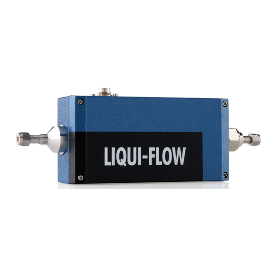
LIQUI-FLOW L30
D o c . n o . : 9 . 1 7 . 0 4 4 C
D a t e : 0 5 - 0 2 - 2 0 1 0
ATTENTION
Please read this instruction manual carefully before installing and operating the instrument.
Not following the guidelines could result in personal injury and/or damage to the equipment.
Advertisement
Table of Contents

Related Manuals for BRONKHORST LIQUI-FLOW L30


Summary of Contents for BRONKHORST LIQUI-FLOW L30
- Page 1 General instructions digital Mass Flow instrument LIQUI-FLOW L30 D o c . n o . : 9 . 1 7 . 0 4 4 C D a t e : 0 5 - 0 2 - 2 0 1 0 ATTENTION Please read this instruction manual carefully before installing and operating the instrument.
- Page 2 BRONKHORST HIGH-TECH B.V. SCOPE OF THIS MANUAL This manual covers the general part of digital LIQUI-FLOW L30 mass flow instruments for liquids. It treats the general instructions needed for the instruments. More information can be found in other documents. Multibus instruments have modular instruction manuals consisting of: General instructions digital LIQUI-FLOW L30 (document nr.
- Page 3 Bronkhorst High-Tech B.V. February 2008 Warranty The products of Bronkhorst High-Tech B.V. are warranteed against defects in material and workmanship for a period of three years from the date of shipment provided they are used in accordance with the ordering specifications and not subjected to abuse or physical damage.
- Page 4 Check if the piping system is clean. For absolute cleanliness always install filters to assure a clean liquid stream. Install the LIQUI-FLOW L30 Meter/Controller in the line and tighten the fittings according to the instructions of the supplier of the fittings.
-
Page 5: Table Of Contents
Liquid flow ............................ 6 1.1.2 Housing ............................6 1.1.3 Valves............................7 Sensor principles ..........................7 1.2.1 LIQUI-FLOW L30 sensor ......................7 Valve principles ........................... 8 1.3.1 Solenoid valve ..........................8 1.3.2 Bellow valve ..........................8 Liquid conversion factors........................9 Software for physical properties of gases and liquids................. 9 INSTALLATION ............................ -
Page 6: Introduction
1.1 General description 1.1.1 Liquid flow The Bronkhorst High-Tech B.V. series LIQUI-FLOW L30 meter/controller for liquids is an accurate device for measuring liquid flows from 2 kg/h up to 20 kg/h with pressures up to 400 bar depending on body rating, virtually independent of pressure and temperature changes. -
Page 7: Valves
BRONKHORST HIGH-TECH B.V. 1.1.3 Valves LIQUI-FLOW L30 controllers are fitted with a modular valve. The valve is attached by means of a port connector. Valves for liquids C2 valve C4 valve C5 valve Direct operating valve for liquids Direct operating valve for gases and Direct operating valve for liquids (“open”... -
Page 8: Valve Principles
BRONKHORST HIGH-TECH B.V. 1.3 Valve principles Control valves are not designed to provide positive shut-off, although some models have excellent capabilities for this purpose. It is recommended to install a separate shut-off valve in the line if required. Also pressure surges, as may occur during system pressurisation must be avoided. -
Page 9: Liquid Conversion Factors
For application of this formula consult Bronkhorst High-Tech B.V. 1.5 Software for physical properties of gases and liquids. Bronkhorst High-Tech B.V. gathered the physical properties of over 600 fluids in a database called FLUIDAT . Application software, such as FLUIDAT on the Net (FOTN), enable the user to calculate accurate conversion factors, not only at 20°C/1 atm, but at any temperature/pressure combination. -
Page 10: Installation
If the instruments have been used with toxic or dangerous fluids the customer should pre-clean the instrument. Important: Clearly note, on top of the package, the customer clearance number of Bronkhorst High-Tech B.V., namely: NL801989978B01 If applicable, otherwise contact your distributor for local arrangements. -
Page 11: Piping
2.11 Seals Bronkhorst High-Tech B.V. has gathered a material compatibility chart from a number of sources believed to be reliable. However, it is a general guide only. Operating conditions may substantially change the accuracy of this guide. -
Page 12: Electromagnetic Compatibility
Therefore they have to comply with the EMC requirements, as they are valid for these instruments. However compliance with the EMC requirements is not possible without the use of proper cables and connector/gland assemblies. For good results Bronkhorst High-Tech B.V. can provide standard cables. Otherwise follow the guidelines as stated below. 1. D-Connector assembly Fold the shield of the cable back over the cable (the shield must be around the cable). -
Page 13: Operation
BRONKHORST HIGH-TECH B.V. OPERATION 3.1 General The Bronkhorst High-Tech B.V. instruments are designed in such a way that they will meet user process requirements in the best possible way. The LIQUI-FLOW L30 meters/controllers can be powered from +15 Vdc to +24 Vdc. -
Page 14: Start-Up
= time for the signal to reach 63.2 % of its final output value. Approx. five time constants is the time to reach the final value. For the LIQUI-FLOW L30 meters the actual response depends on model and flow rate. 3.5.2 Controllers The dynamic response of a controller is factory set. -
Page 15: Analog Operation
BRONKHORST HIGH-TECH B.V. 3.7 Analog operation Digital instruments can be operated with analog signals through the 8-pin circular connector. The instruments are compatible in use with analog instruments on this point. Analog operated instruments, can be hooked up using an 8-wire shielded cable, connected according to the Bronkhorst High-Tech standard. -
Page 16: Bus / Digital Operation
BRONKHORST HIGH-TECH B.V. 3.8 BUS / digital operation Operation via fieldbus reduces the amount of cables to build a system of several instruments and offers more parameter values to be monitored/changed by the user. See instruction manual: operating digital mass flow / pressure instruments for more details (document nr. -
Page 17: Maintenance
No routine maintenance is required to be performed on the meters or controllers. In case of severe contamination it may be required to clean the valve orifice separately. 4.2 LIQUI-FLOW L30 sensor The user cannot change the flow range of a liquid flow sensor. The sensor is an integral part of the instrument and cannot be removed from it. -
Page 18: Bellows Valve
BRONKHORST HIGH-TECH B.V. 4.4.2 Bellows valve These valves are suited for low pressure or vacuum applications. The user should not disassemble this model. 4.5 K -value calculation This calculation method can be used to determine the K -value of the main orifice of a control valve. -
Page 19: Digital Instrument
BRONKHORST HIGH-TECH B.V. DIGITAL INSTRUMENT See document number 9.17.023 for detailed description. INTERFACE DESCRIPTION For a description of the available interfaces see document numbers: 9.17.024 for FLOW-BUS 9.17.025 for PROFIBUS-DP 9.17.026 for DeviceNet 9.17.027 for RS232 9.17.035 for Modbus (special request) 9.17.044... -
Page 20: Troubleshooting
7.1 General For a correct analysis of the proper operation of a LIQUI-FLOW L30 meter or controller it is recommended to remove the unit from the process line and check it without applying fluid supply pressure. In case the unit is dirty, this can be ascertained immediately by loosening the compression type couplings and, if applicable the flange on the inlet side.
Need help?
Do you have a question about the LIQUI-FLOW L30 and is the answer not in the manual?
Questions and answers