Table of Contents
Advertisement
Quick Links
Advertisement
Table of Contents

Subscribe to Our Youtube Channel
Related Manuals for Metos RN 20


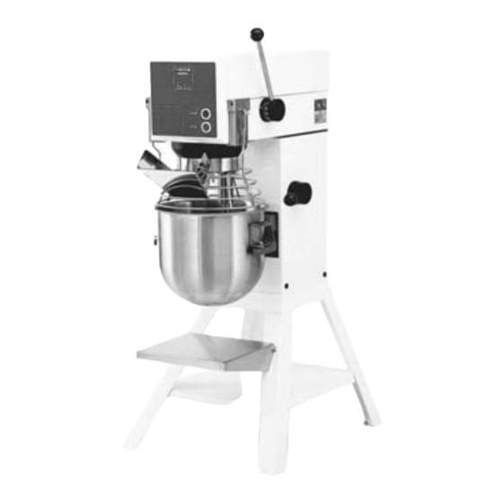
Summary of Contents for Metos RN 20
- Page 1 MIXER RN 20 Service Manual S/N: Valid from: Rev.: 2.0...
- Page 3 Dear Customer, Congratulations on deciding to choose a Metos appliance for your kitchen activities. You made an excellent choice. We will do our best to make you a satisfied Metos customer like thousands of customers we have around the world.
- Page 4 5.10.2004 Rev. 1.0...
-
Page 5: Table Of Contents
5.10.2004 Rev. 1. General ......................1 1.1 Symbols used in the manual ..................1 1.2 Symbols used on the appliance ..................1 1.3 Checking the relation of the appliance and the manual ..........1 2. Safety ......................2 2.1 Safe use of the appliance ....................2 3. - Page 6 5.10.2004 Rev.
-
Page 7: General
5.10.2004 Rev. 1.0 General 1. General Carefully read the instructions in this manual as they contain important information re- garding proper, efficient and safe installation, use and maintenance of the appliance. Keep this manual in a safe place for eventual use by other operators of the appliance. The installation of this appliance must be carried out in accordance with the manufactur- er’s instructions and following local regulations. -
Page 8: Safety
5.10.2004 Rev. 1.0 Safety 2. Safety 2.1 Safe use of the appliance Check that the bowl is in working position before starting the mixer. Do not put your fingers in the bowl while the mixer is running. To the attachment drive must be connected original attachments only. -
Page 9: Functional Description
5.10.2004 Rev. 1.0 Functional description 3. Functional description 3.1 Application of the appliance The mixer is meant for producing masses and doughs which will not release reactions or liberate material which can harm the user. -
Page 10: Operation Instructions
5.10.2004 Rev. 1.0 Operation instructions 4. Operation instructions 4.1 Operation procedures Place the bowl in the bowl arms. Ensure that the bowl is placed correctly. Place the mixing tool in the bayonet shaft. The pin of the tool must be turned into the bay- onet hole. - Page 11 5.10.2004 Rev. 1.0 Operation instructions Raise the bowl to working position by pulling the handle forward. Ensure that the bowl is placed correctly while the bowl is lifted. If the mixer is equipped with a timer, set the mixing time by turning the timer to the right. The mixer will stop automatically, when the time runs out.
- Page 12 5.10.2004 Rev. 1.0 Operation instructions Push the speed selector lever to obtain the required speed. The speed must be changed only when the mixer is running. Recommended maximum speeds Before the mixer is stopped, the speed selector lever should be moved to the lowest speed. The mixer must not be started when loaded in high speed position.
-
Page 13: After Use
5.10.2004 Rev. 1.0 Operation instructions Stop the mixer by pressing the red stop button >STOP<. Take care not to overload the mixer.Tough and heavy doughs might reduce the working capacity of the mixer by 75%. The capacity will be further reduced if the speed of the tool is increased beyond what is recommended or if a wrong tool is used. -
Page 14: Lubrication And Maintenance
5.10.2004 Rev. 1.0 Operation instructions 4.2.2 Lubrication and Maintenance When the mixer is used regularly, the varispeed system must be lubricated approx. once per month. When the mixer is used intensively or often used without changes in speed ,the lubrication intervals should be shortened. -
Page 15: Installation
5.10.2004 Rev. 1.0 Installation 5. Installation 5.1 Installation The mixer can be placed direct on the floor. Foundation bolts in the floor are only neces- sary under special conditions, e.g. in ships. If the 20 L mixer is placed on a bench stand, it must be fastened with the enclosed bolts. -
Page 16: Service
5.10.2004 Rev. 1.0 Service 6. Service 6.1 Service instructions Before servicing the mixer must be disconnected Remove the top cover 1of the mixer and the plastic cover 43 by removing the two screws The attachment engagement hub 3 is taken out by removing the plastic cover 4 and the four bolts 5. - Page 17 5.10.2004 Rev. 1.0 Service The special V-belt 7 is exchanged in the following way: • remove the top cover 1 of the mixer and the plastic cover 43 • press the speed selector lever 8 back towards the back of the mixer so that the spe- cial V-belt is loosened, and take off the special V-belt •...
- Page 18 5.10.2004 Rev. 1.0 Service • the top cover 1 of the mixer, the attachment engagement hub 3, the special V-belt 7, and the control box 6 are removed • the plastic ring 26 can be taken off by knocking it gently on the front edge, and then press a screwdriver in between the plastic ring and the metal plate at the top of the plastic ring •...
- Page 19 5.10.2004 Rev. 1.0 Service When the lower fork 15 and the spring 34 are mounted, the speed selector lever 8 is turned counter clockwise, so that it points horizontally backwards, at the same time as the lower fork is pressed gently down. When the speed selector lever 8 is now turned clockwise, it will catch the toothed rack 35 and pull down the lower fork.
- Page 20 5.10.2004 Rev. 1.0 Service • start the mixer and control the measure C on both pulley sets at high and low speed resp. • be aware that the pin 39 0n the lower part 32 of the pulley set is to be placed as shown on the drawing opposite.
-
Page 21: Lubrication And Maintenance
5.10.2004 Rev. 1.0 Service If a microswitch for bowl lift 58 is required it must be adjusted in a way that it will not be activated when the bowl is in working posi- tion. Adjusting of bowl height: • lower the bowl arms •... - Page 22 5.10.2004 Rev. 1.0 Service When repairing the planetary head which is greased for life, the grease Q8 GIOTTO NLGL 1 should be used in gear wheel, gear wheel rim and gear for attachment drive, if any. The needle bearings of the planetary head must not be greased with this type of grease Only grease Q8 GIOOTO NLGI 1 can be used, and it must not be mixed with other types of grease.
-
Page 23: Spare Parts
5.10.2004 Rev. 1.0 Spare parts 7. Spare parts General parts ........21 Transmission......... 25 Planetary head ........29 Attachment drive........33 Machine column ........35 Safety guard .......... 39 Lifting system........41 Electric components ......43... - Page 24 5.10.2004 Rev. 1.0 Spare parts...
-
Page 25: Voltage Codes
2/PE 220−240V 50Hz 3/N/PE∼415/240V 50Hz 3/PE∼230V 50Hz 3/PE∼220V 60Hz 3/PE∼380 50Hz 3/PE∼400V 50Hz 3/PE∼415V 50Hz 3/PE∼440V 60Hz 3/PE∼460V 60Hz 3/PE∼480V 60Hz 1/N/PE~220-240V 50Hz 2/PE~220-230V 60Hz 3/N/PE∼400/230V 50Hz 3/PE∼230V 60Hz 1/N/PE~100V 50-60Hz 7.2 Product codes Product code Full name Model codes RN 20... - Page 26 5.10.2004 Rev. 1.0 Spare parts...
- Page 27 20/12L scraper with nylon and holder 42RN20AT 20/12L scraper with teflon and holder 42R20-102 20L scraper with nylon w/o holder 42R20-102T 20L scraper with teflon w/o holder 42RN20A102 20/12L with scraper nylon w/o holder 42RN20A102T 20/12L scraper with teflon w/o holder 20=RN 20...
- Page 28 5.10.2004 Rev. 1.0 Spare parts...
- Page 29 Code Date from Model Description Module:General parts 42R20-104 20L nylon blade 42R20-104T 20L teflon blade 42RN20A104 RN20/12L nylon blade 42RN20A104T RN20/12L teflon blade 42R20-101M holder for scraper STA5648 screw M8x100 STA6020 washer D18x8,4x1,25 STA5086 screw M5x12, stainless steel 20=RN 20...
- Page 30 5.10.2004 Rev. 1.0 Spare parts...
- Page 31 6010 2RS1 RN20-17 varispeed collar STA5451 screw M8x16 STA6009 washer D8 5472142 grease gun RN20-47Z speed selector lever,assy RN20-47M speed selector lever 5472006 knob RN20-400 spring RN20-47.20 thrust pad RN20-47.10 disc with arrow RN20-47.11 retaining disc 20=RN 20...
- Page 32 5.10.2004 Rev. 1.0 Spare parts...
- Page 33 Spare parts Code Date from Model Description Module:Transmission STA5819 nut M6 STA5601 pointed screw M6x20 RN20-46Z toothed rack assy STA6028 washer D8 STA3407 circlip 19U 5472207 lower fork RN20-16.5 spring RN20-305 pin bolt STA5452 screw M8x50 STA5812 nut M8 20=RN 20...
- Page 34 5.10.2004 Rev. 1.0 Spare parts...
- Page 35 BK1816 RN20-2Z eccentric head compl. STA6460 groove pin D8x24 STA3514 circlip 52L 5472033 bayonet shaft assy STA3470 circlip SW17 STA2008 key B5x5x43 5472109 spring f/33 5472106 ball 1/4 s.s. 1000 R20-98 ball bearing f/30 1010 5472037 distance piece 20=RN 20...
- Page 36 5.10.2004 Rev. 1.0 Spare parts...
- Page 37 1100 5472034 distance piece 1110 R20-97 ball bearing f/33n, 6205 2RS1C3 1120 STA5641 screw M8x80 1130 W20-272 headcap 1140 W20-272.1 headcap prepared for scraper 1150 5472209 rubber ring f/33 1160 RN20-272.1 cover for planetary head upper 20=RN 20...
- Page 38 5.10.2004 Rev. 1.0 Spare parts...
- Page 39 1230 RN20-211 rubber gasket 1240 STA5631 screw M8x20 1250 STA6038 lockwasher M8 1260 RN20-50.1Z attachment drive shaft compl.front 1270 STA2031 key B8x7x30 1280 R15-105 ball bearing f/50 6005 1290 RN20-37 distance piece 1300 5472208 wormwheel STA3410 circlip 25U 20=RN 20...
- Page 40 5.10.2004 Rev. 1.0 Spare parts...
- Page 41 1510 RN20-310 retaining spring f/plate 1520 STA5441 screw M8x150 1530 RN20-302Z suspension hook complet 1540 STA5831 lock nut M6 1550 24RN20-2MO stand, white 1560 24RN20-9MO tray for stand, white 1240 STA5631 screw M8x20 1570 24RN20-18 feet for stand 20=RN 20...
- Page 42 5.10.2004 Rev. 1.0 Spare parts...
- Page 43 Code Date from Model Description Module:Machine column 1580 24RN20-19 intermediate piece 3 mm 1590 24RN20-20 intermediate piece 6 mm 1600 STA5609 screw M8x12 1610 STA6001 nylon washer D17x8,4x1,6 1620 00001-21020-004 stand compl. white 1630 00001-21020-003 feet compl. White 20=RN 20...
- Page 44 5.10.2004 Rev. 1.0 Spare parts...
- Page 45 1820 56SN20-24 distance washer 1830 RN20-193M cable for microswitch 1840 STA5270 screw M4x30 1850 STA5816 nut M4 1860 56SN20-28 front part, grid. RN20 1870 56SN20-26 rear part, grid. RN20 1880 56G20-270 detachable filling skid for french s.gua 20=RN 20...
- Page 46 5.10.2004 Rev. 1.0 Spare parts...
- Page 47 2030 RN20-68.5Z bowl arm guide rod compl.f.microswitch 2040 56RN20-15 fitting for microswitch compl. 1770 5472056 microswitch 2050 56SN20-50 fitting for microswitch 2060 56SN20-51 fitting plate 2070 STA5125 screw M3x16 1830 RN20-193M cable for microswitch 2080 STA6499 tubular rivet 20=RN 20...
- Page 48 5.10.2004 Rev. 1.0 Spare parts...
- Page 49 2290 STA3078 cable inlet 2300 STA3000 cable inlet PG11 2310 STA3010 nut PG11 2320 RN20-194.2M cable 5x1,5 white 2330 RN20-194.1M cable 4x1,5 white 2340 RN20-194.7M cable 3x1,5 white 2350 R15-244 machine number sign 2360 STA 5230 screw M4x10 20=RN 20...
- Page 50 5.10.2004 Rev. 1.0 Spare parts...
- Page 51 Spare parts Code Date from Model Description Module:Electric components 2370 RN20-151 fittings for relay 2380 RN20-194M cable 4x1,5 white 2390 RN20-194.6M cable 3x1,5 white 2400 5476505 auxiliary switch CB-S 2410 thermal overload relay 2420 relay with coil 2430 motor 20=RN 20...
- Page 52 5.10.2004 Rev. 1.0 Spare parts...
-
Page 53: Technical Specifications
5.10.2004 Rev. 1.0 Technical specifications 8. Technical specifications Wiring diagrams Installation drawing RN20 Installation drawing RN20-Table Installation drawing RN20-Stand... - Page 54 Wiring diagrams...
- Page 55 Installation drawing RN20...
- Page 56 Installation drawing RN20-Table...
- Page 57 Installation drawing RN20-Stand...
- Page 58 Dimensions LxWxH/stand 720x566x1286 Infinitely variable speed 75-350 Meat mincer 70+82mm Vegetable cutter GR20+ 20=RN 20 Capacity Chart RN 20 Egg white 1 L=30 eggs Whipped cream Mayonnaise (L Oil) Mashed potatoes 10 kg Biscuit bottom 8-10 Dough L liquid AR 60% 3.75 L...
Need help?
Do you have a question about the RN 20 and is the answer not in the manual?
Questions and answers