Parker Gemini GT6K Series Quick Reference Manual
Digital stepper environmental specifications controller/drives
Hide thumbs
Also See for Gemini GT6K Series:
- Programmer's manual (254 pages) ,
- Hardware installation manual (111 pages)
Table of Contents
Advertisement
Quick Links
Gemini 50-Pin Connector to Flying Leads Cable
Enable
1
Digital Ground
Reset
3
reserved
4
reserved
5
Digital Ground
6
Digital Ground
7
Black
reserved
8
White/Black
reserved
9
Red
reserved
10
White/Red
reserved
11
Green
reserved
12
White/Green
reserved
13
Orange
Step+ Out
14
White/Orange
Step– Out
15
Blue
Direction+ Out
16
White/Blue
Direction– Out
17
Yellow
reserved
18
White/Yellow
reserved
19
Digital Ground
20
Analog Output A
21
Analog Output B
22
Brown
Analog Input+
23
White/Brown
Analog Input–
24
Analog Ground
25
VINref
26
CNTRL-P: Lim 1-3
27
(Pos) Limit 1
28
(Neg) Limit 2
29
In/Lim Ground
30
(Home) Limit 3
31
In/Lim Ground
32
CNTRL-P: In 1-5
33
Input 4
34
(TRG M) Input 5
35
In/Lim Ground
36
(TRG A) Input 1
37
(TRG B) Input 2
38
Input 3
39
In/Lim Ground
40
Output 1
41
Output Ground
42
Output 2
43
Output Ground
44
Output 3
45
Output 4
46
Output Ground
47
Output 5
48
Output 6
49
Output Ground
50 Pin Connector
Protective Circuits
Short Circuit Protection
Inrush Current Protection
Drive Overtemperature Protection
Undervoltage Protection
Regeneration Protection
Environmental Specifications
°F)
Operating Temperature:
Still Air:
45°C
°F)
Moving Air: 50°C
°C
°F – 185°F)
Storage Temperature:
-40° –
Humidity:
0 –
Shock:
15g, 11 msec half sine
Vibration:
10 – 2000 Hz at 2g
✵
✵
www.comoso.com
White/Violet
White/Gray
Red/Black
Red 16 AWG
Black 16 AWG
Black
White/Black
Red
White/Red
Green
White/Green
Orange
White/Orange
Blue
White/Blue
Yellow
White/Yellow
White/Black/Orange
White/Black/Green
Green/Black
Brown
White/Brown
Yellow/Red
Gray/Blue
Yellow/Green
Gray/Orange
Blue/Red
Blue/Orange
Gray
Pink
White/Pink
Orange/Black
White/Black/Blue
Yellow/Blue
Yellow/Orange
Blue/Yellow
Violet
White/Black/Red
Yellow/Black
White/Black/Yellow
Blue/Black
Green/Red
Gray/Green
Gray/White
Yellow/White
Blue/White
Gray/Brown
Yellow/Brown
Shield
Cable Part Number: 71-016943-10
Troubleshooting
Commonly used status commands (binary status bits are
numbered 1 to n, from left to right):
TERRLG Error log reports the last 10 error conditions (cleared
with CERRLG).
TASF
General report, including fault conditions.
TASXF
Additional report of conditions not covered with TAS.
TCS
If TASX bit #7 or bit #28 is set, you can identify the
cause with TCS.
TINOF
Bit 6 shows status of Enable input; 1 = OK for motion.
TIN
Status of digital inputs.
TLIM
Status of home and end-of-travel limits.
TIO
Status of expansion I/O.
TOUT
Status of digital outputs.
TSSF
Report of system status bits.
TSTAT
Report of system statistics.
You must configure all motor parameters. Be sure to follow the
drive configuration procedure (see Hardware Installation Guide).
The drive can not be enabled (DRIVE1) unless the Enable input
is grounded and the Reset input is not grounded.
Use one of these methods to reset the drive/controller:
• RESET command (resets drive & internal controller).
• DRESET command (resets drive, but not controller).
• Momentarily close the Reset input.
• Cycle power to the drive.
✵
✵
Quick Reference
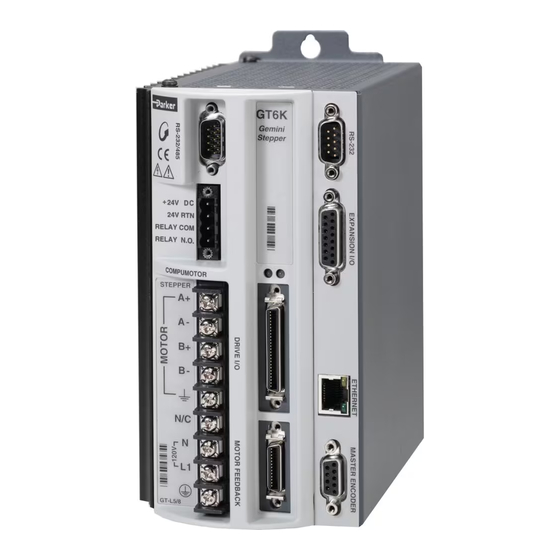
Gemini GT6K Series
Digital Stepper
Controller/Drives
Compumotor Division
Parker Hannifin Corporation
p/n 88-019931-01 A
(effective October 15, 2001)
Guide
Advertisement
Table of Contents

Related Manuals for Parker Gemini GT6K Series


Summary of Contents for Parker Gemini GT6K Series
- Page 1 Troubleshooting Short Circuit Protection Commonly used status commands (binary status bits are Inrush Current Protection Gemini GT6K Series numbered 1 to n, from left to right): Drive Overtemperature Protection Undervoltage Protection TERRLG Error log reports the last 10 error conditions (cleared Regeneration Protection with CERRLG).
- Page 2 www.comoso.com Quick Reference Guide RS-232/485 Connector – COM1 – Port 1 RS-232 Connector – COM2 – Port 2 Expansion I/O Connector To configure drive parameters, connect a PC to this port. Connect an RP240, or use this port for RS-232. Connect as many as eight EVM32-II I/O modules in series, Use Motion Planner for drive configuration.
Need help?
Do you have a question about the Gemini GT6K Series and is the answer not in the manual?
Questions and answers