Agilent Technologies PNA Series User And Programming Manual
Network analyzer
Hide thumbs
Also See for PNA Series:
- Service manual (327 pages) ,
- Installation and quick start manual (32 pages) ,
- Installation note (24 pages)

Related Manuals for Agilent Technologies PNA Series


Summary of Contents for Agilent Technologies PNA Series
- Page 1 Agilent PNA Series Network Analyzer Printed Version of PNA Help User’s and Programming Guide Supports Firmware A.09.80 Sept. 16, 2012...
- Page 2 (November 1995), as applicable in any technical data. Certification Agilent Technologies, Inc. certifies that this product met its published specifications at the time of shipment from the factory. Agilent Technologies, Inc. further certifies that its calibration measurements are traceable to the United States National Institute of Standards and Technology, to the extent allowed by the Institute's calibration facility, and to the calibration facilities of other International Standards Organization members.
- Page 3 TABLE OF CONTENTS Whats New Administrative Tasks Microsoft EULA PNA User Accounts and Passwords Computer Properties Error-check and Disk Defragmenter Operating System Recovery Wake PNA at Specified Time Windows Considerations Quick Start Front Panel Tour Rear Panel Tour Powering the PNA ON and OFF Traces, Channels, and Windows on the PNA QuickStart Dialog Basic Measurement Sequence...
- Page 4 Trigger Model Animation Data Format Scale Preconfigured Measurement Setups Path Configurator Phase Control Customize Your Analyzer Screen Copy Channels DC Control ADC Measurements Undo/Redo 2. Optimize a Measurement Dynamic Range Number of Data Points Phase Accuracy Phase Coherent Measurements Electrically Long Devices Reflection Accuracy Measurement Stability Noise Reduction Techniques...
- Page 5 CalPod Calibration Preferences Modify Cal Kits Power Calibration Fixture Compensation Port Extensions Characterize Adaptor Macro Concepts Calibration Overview Measurement Errors Accurate Calibrations Calibration Thru Methods Validity of a Cal Calibration Standards Swap Adapters Method Delta Match Calibration 4. Analyze Data Locate Data Using Markers Math &...
- Page 6 CalibrateAllChannels Object Calibrator Object CalKit Object CalManager Object CalSet Object CalSets Collection CalStandard Object Capabilities Object Channel Object Channels Collection ComColors Object ComTraceColors Object Converter_Object ConverterEmbeddedLO Object CorrectionMethods Object DCStimulus Object E5091Testset Collection E5091Testset Object ECalModule Object ECalModules Collection ECalUserCharacterizer Object EmbeddedLO Object EmbeddedLODiagnostic Object ENRFile Object...
- Page 7 Gating Object GlobalPowerLimit Object GroupDelayAperture Object GuidedCalibration Object GuidedCalibrationPowerSensor Object GuidedCalibrationPowerSensor Object#history GuidedCalibrationPowerSensors Collection HWAuxIO Object HWExternalTestSetIO Object HWMaterialHandlerIO Object IIFConfiguration Object IMixer Interface IMSpectrum Object InterfaceControl Object Limit Test Collection LimitSegment Object Marker Object Measurement Object MeasurementClassProperties Object Measurements Collection NAWindow Object NAWindows Collection NoiseCal Object...
- Page 8 PowerSensors Collection PowerSensorCalFactorSegment Object PowerSensorCalFactorSegmentPMAR Object PowerSensorAsReceiver Object Preferences Object PSaturation Object PulseGenerator Object PulseMeasurementControl Object ReceiverLevelingConfiguration Object SCPIStringParser Object Segment Object Segments Collection SignalProcessingModuleFour Object SMC Type Object SourcePowerCalibrator Object SweptIMD Object SweptIMDCal Object TestsetControl Object Trace Object Traces Collection Transform Object TriggerSetup Object VMC Type Object...
- Page 9 ADCCaptureMode ALCLevelingMode AllowArbitrarySegments Alternate Sweep AmbientTemperature AnalysisCWFreq Property AnalysisEnable Property AnalysisIsDiscreteFreq Property AnalysisXAxis Property Application Arrange Windows Attenuator Mode Attenuator AutoCWSweepTime Property AutoDetection Property AutoIFBandWidth Property AutoIFBWAdjustment AutoIFGain Property AutoOptimizePRF Property AutoOrient AutoOrientTuner Property AutoPortExtConfig AutoPortExtDCOffset AutoPortExtLoss AutoPortExtSearchStart AutoPortExtSearchStop AutoPortExtState AutoPulseTiming Property AutoSelectPulseGen Property AuxiliaryTriggerCount...
- Page 10 BackOff Property BackOffGain Property BackOffPIn Property BackOffPout Property BalancedMode BalPort1PhaseOffset BalPort1PowerOffset BalPort1StartPhase BalPort1StopPhase BalPort2PhaseOffset BalPort2PowerOffset BalPort2StartPhase BalPort2StopPhase Bandwidth Target Bandwidth Tracking BB_BalPort1Negative BB_BalPort1Positive BB_BalPort2Negative BB_BalPort2Positive BalSMeasurement Property BBalMeasurement Property Begin Response Begin Stimulus BroadbandTuningSpan BS_BalPortNegative Property BS_BalPortPositive Property BS_SEPort Property Bucket Number Cal Factor Cal Type (applied)
- Page 11 CalibrationFrequencies Cal KitType CalKitType (FCA) CalKitType CalKitTypes Property CalMethod CalMethod (imd) Cal Power CalSet Property Center Center (Meas) Center Frequency Channel Number Channels Property CharacterizationNumber CharacterizeMixerOnly CharFileName CharMixerReverse CitiContents CitiFormat CmnModeZConvPortImag CmnModeZConvPortReal CmnModeZConvPortZ0 CmnModeZConvState CompatibleCalKits CompositeNormalizationMode CompositeNormalizedCSOPower CompositeNormalizedCTBPower Compression Property CompressionAlgorithm CompressionBackoff CompressionDeltaX...
- Page 12 CompressionPout CompressionSaturation Property ConnectorType ConnectorType ECal ControlLines Count Couple Ports CoupleChannelParams Coupled Coupled Markers CoupledParameters - Gate CoupledParameters - Transform CouplePhasePortSettings Property CoupleTonePower CpuRevision Property CSONumDistortionProducts CSOOffset CTBOffset CTBXMODNumCarriers CustomCalConfiguration Property CustomChannelConfiguration CustomMeasurementConfiguration Property CW Frequency CWFrequency CS Property Data DataAndLimits Property DataCount DataInCompactForm...
- Page 13 DeltaFrequency DeltaFrequencyStart DeltaFrequencyStop DeltaMarker Description DescriptiveText DeviceInputPort (FCA) DeviceInputPort DeviceNames Property DeviceOutputPort (FCA) DeviceLinearPowerLevel DeviceOutputPort 1000 DeviceType Property 1001 DiffPortMatch_C 1002 DiffPortMatch_G 1003 DiffPortMatch_L 1004 DiffPortMatch_R 1005 DiffPortMatchMode 1006 DiffPortMatchState 1007 DiffPortMatchUserFilename 1008 DiffZConvPortImag 1009 DiffZConvPortReal 1010 DiffZConvPortZ0 1011 DiffZConvState 1012 Display Format 1013...
- Page 14 DUTTopology 1028 Dwell Time 1029 DwellPerPoint Property 1030 ECALCharacterization (smc) 1031 ECALCharacterization (vmc) 1032 ECALCharacterizationEx 1033 ECalID 1034 ECALIsolation 1035 ECALModuleNumberList 1036 EcalOrientation 1037 EcalOrientation1Port 1039 EcalOrientation2Port 1040 ECALPortMapEx 1042 ElecDelay Medium 1044 ElecDistanceDelay 1045 ElecDistanceDelayUnit 1046 Electrical Delay 1047 Element 1048 Elements...
- Page 15 ENRFile 1071 ENRID 1072 ENRSN 1073 EqualTonePower Property 1074 Error Correction 1075 ErrorCorrection(Channel) 1076 ErrorCorrectionIndicator Property 1077 ExtendedProperties Property 1078 External ALC 1079 ExternalDeviceDeActivatePolicy Property 1080 ExternalTriggerConnectionBehavior 1081 ExternalTriggerDelay 1083 F1Frequency 1084 F2Frequency 1085 FailedTraces Property 1086 FastCWPointCount 1087 FastMode 1088 Filter BW 1089...
- Page 16 Frequency 1111 FrequencyCenter 1112 FrequencyCenterCenter 1113 FrequencyCenterspan 1114 FrequencyCenterStart 1115 FrequencyCenterStop 1116 Frequency Offset Divisor 1117 Frequency Offset Frequency 1118 Frequency Offset Multiplier 1119 FrequencyOffsetRangeForCalComputations Property 1120 Frequency Offset Override To CW 1121 Frequency Offset State 1122 FrequencyType Property 1123 Gain Property 1124 GainLinear Property...
- Page 17 IFFrequency 1149 IFFrequencyMode 1150 IFSideband 1151 IFSideband (conv) 1152 IFStartFrequency 1153 IFStopFrequency 1154 ImpedanceStates 1155 Impulse Width 1156 IMToneIFBandwidth 1157 InactiveLabels Property 1158 Include2ndOrderProduct 1159 IncludeReverseSweep Property 1160 IndexState 1161 Input A 1162 Input B 1163 Input C 1164 InputDenominator 1165 InputFixedFrequency 1166...
- Page 18 IsFrequencyOffsetPresent 1187 IsHold 1188 IsMarkerOn 1189 IsolationAveragingIncrement 1190 IsOn 1191 IsReceiverStepAttenuatorPresent 1192 IsReferenceBypassSwitchPresent 1193 IsSParameter 1194 Item Property 1195 Items Property 1197 IterationNumber 1198 IterationsTolerance 1199 Kaiser Beta 1200 1201 1202 1203 1204 Label 1205 Label Testset 1206 LANConfiguration 1207 LastCalPassedTolerance 1208 LastLevelingAsSPC...
- Page 19 Locator 1224 Lock Property 1226 LODeltaFound 1227 LODenominator 1228 LOFixedFrequency 1229 LOFrequencyDelta 1230 OBS_LogMagnitudeOffset 1231 LOName 1232 LONumerator 1234 LOPower 1235 LORangeMode 1236 LORangeMode cv Property 1237 Loss 1238 Loss (sourceCal) 1239 LOStage 1240 LOStartFrequency 1241 LOStartPower 1242 LOStopFrequency 1243 LOStopPower 1244 LowAmplitude Property...
- Page 20 MarkerReadoutYPosition Property 1262 Markers Property 1263 Marker State 1264 MarkerSymbol Property 1265 MasterFrequency Property 1266 MasterMode Property 1267 MasterPeriod Property 1268 MasterWidth Property 1269 Marker Type 1270 Marker X-axis Value 1271 Marker Y-axis Value 1272 MatchCorrectPower 1274 Maximum Frequency 1275 MaximumFrequency (capabilities) 1276 MaximiumFrequency (sourceCal)
- Page 21 MinimumIFFrequency Property 1301 MinimumNumberOfPoints 1302 MinimumReceiverStepAttenuator 1303 MinimumSourceALCPower 1304 MixerCharacterizationFile Property 1305 Mode 1306 Mode-iTMSA 1307 Move Property 1308 Multiplier 1309 Name (Calset) 1310 Name (CalKit object) 1311 Name config 1312 Name element 1313 Name ExtDev Property 1314 Name FOMRange 1315 Name (meas) 1316...
- Page 22 NormalizePoint Property 1340 NormalizePoint SMC Property 1341 Number (meas) 1342 Number 1343 NumberOfFrequencyPoints 1344 Number of Points 1345 Number of Points (Meas) 1347 NumberOfPorts 1348 NumberOfPorts(Testset) 1349 NumberOfPowerPoints 1350 NumberOfSweeps 1351 Offset 1352 OffsetReceiverAttenuator 1353 OffsetSourceAttenuator 1354 OmitIsolation 1355 OneReadoutPerTrace 1356 Options 1357...
- Page 23 PathCalMethod 1382 PathConfigurationElement Property 1384 PathThruMethod 1385 Peak Excursion 1387 Peak Threshold 1388 PeakTo Peak 1389 Percent Property 1390 PerformPowerCalibration 1391 Period 1392 Phase Offset 1393 PhaseAsFixture 1394 PhaseControlMode Property 1395 PhaseCorrectionData Property 1396 PhaseCorrectionEnabled Property 1397 PhaseIterationNumber Property 1398 PhaseParameter Property 1399 PhaseParameterModes Property...
- Page 24 PortArbzReal 1422 PortArbzState 1423 PortArbzZ0 1424 PortCatalog 1425 PortCLogic 1426 PortCMode 1427 PortCoupleToSystemMedia 1428 PortCoupleToSystemVelocity 1429 PortDelay 1430 PortDescription 1431 PortDistance 1432 PortDistanceUnit 1433 PortExtState 1434 PortExtUse1 1435 PortExtUse2 1436 PortFreq1 1437 PortFreq2 1438 Port Label 1439 PortLogic 1440 PortLoss1 1441 PortLoss2 1442...
- Page 25 PowerCalibrationPowerLevel Property 1460 PowerLevel 1461 PowerLevel (CalAll) Property 1462 PowerMax 1463 PowerMaxIn Property 1464 PowerMaxOut Property 1465 Power Meter Channel 1466 Power Meter GPIBAddress 1467 PowerMin 1468 PowerOffset 1469 PowerOffset (CalAll) Property 1470 PowerOnDuringRetraceMode 1471 PowerSensorCalKitType Property 1472 PowerSensorCalKitType 1473 PowerSensorConnectorType 1474 PowerSensorConnectorType Property...
- Page 26 ReadyForTriggerState 1500 RecallSoftkeysMostRecent Property 1501 Receiver Attenuator 1502 ReceiverAttenuator Property 1503 ReceiverCount 1504 ReceiverRatio Property 1505 ReceiverStepAttenuatorStepSize 1506 ReceiverTemperature Property 1507 Receive Port 1508 RedTraceOnFail Property 1509 ReduceIFBandwidth 1510 ReferenceCalFactor 1511 Reference Marker State 1512 ReferenceReceiver 1513 Reference Level 1514 Reference Position 1515 RemoteCalStoragePreference...
- Page 27 Search Function 1538 SearchFailures Property 1539 SearchSummary Property 1540 SecurityLevel 1541 Segment Number 1542 SegmentCount Property 1543 SegmentFixedFrequency Property 1544 SegmentFixedPower Property 1546 SegmentIFBandwidth Property 1548 SegmentIsInputGreaterThanLO Property 1549 SegmentMixingMode Property 1551 SegmentPoints Property 1553 SegmentRangeMode Property 1554 SegmentStartFrequency Property 1556 SegmentState Property 1558...
- Page 28 SourceImpedance Property 1583 Source Port 1584 SourcePortCount 1585 SourcePortMode 1586 SourcePortNames 1587 SourcePowerCalPowerOffset 1589 Source Power Correction 1590 Source Power Option 1591 Source Power State 1592 SourcePullForSParameters Property 1593 SourceStepAttenuatorStepSize Property 1594 Span 1595 Span (Meas) 1596 SParameterCalPorts Property 1597 SpectrumCenterFrequency 1598 SpectrumSpanFrequency...
- Page 29 Stage3ParameterMinimum Property 1622 Stage3Parameters Property 1623 Standard Deviation 1624 Standard For Class 1625 Start Frequency_CS 1627 Start Frequency 1628 Start Power 1630 Start 1631 Start (Meas) 1632 Start DC Property 1633 StartFrequency PR Property 1634 StartPhase Property 1635 StartPowerEx 1636 StartRatioedPower Property 1637 State GPL Property...
- Page 30 SupportedParameters Property 1664 Sweep Delay Property 1665 SweepDwell Property 1666 SweepEndMode 1667 SweepHoldOff 1668 SweepOrder 1669 SweepSpeedMode 1670 Sweep Generation Mode 1671 Sweep Time 1672 SweepTimeOption 1673 SweepType (imd) 1674 SweepType (ims) 1676 Sweep Type 1677 System Impedance Z0 1679 SystemName 1680 Target Value...
- Page 31 TrackingChannel 1707 TrackingEnable 1708 TrackingManualStepEnable 1709 TrackingStepIndex 1710 Transform Mode 1306 Trigger Delay 1711 TriggerInPolarity 1712 TriggerInType 1714 TriggerMode ExtDev Property 1716 TriggerOutDuration 1717 TriggerOutInterval 1718 TriggerOutPolarity 1719 TriggerOutPosition 1720 TriggerOutputEnabled 1721 TriggerPort Property 1722 TuningIFBW 1723 TuningMode 1724 TuningSweepInterval 1725 TwoPointGroupDelayAperture Property 1726...
- Page 32 UserName 1748 UserPresetEnable 1749 Valid 1750 ValidConnectorType 1751 Value element 1753 Values 1754 Velocity Factor 1755 View 1756 Visible 1757 WGCutoffFreq 1758 WideBandDectionState Property 1759 Width 1760 Window Number 1761 Window State 1762 XAxisAnnotation 1763 XAxis Point Spacing 1764 XAxisStart 1765 XAxisStop 1766...
- Page 33 Add External Device Method 1791 Add GuidedPowerSensors Method 1792 Add Testset 1793 AddSegment Method 1794 Allow All Events 1795 AllowChannelToSweepDuringCalAcquisition 1796 Allow Event Category 1798 Allow Event Message 1799 Allow Event Severity 1800 Apply 1801 ApplyDeltaMatchFromCalSet 1802 ApplyPowerCorrectionValuesEx 1803 ApplySourcePowerCorrectionTo 1804 AssignSourceToRole 1805...
- Page 34 CopyToChannel 1838 Create SParameter Method 1839 CreateCalSet 1840 CreateCustomCal 1841 CreateCustomCalEx 1842 CreateCustomMeasurementEx 1844 CustomCalConfiguration Method Create Measurement 1849 DataToMemory 1853 Deembed Method 1854 Delete 1856 Delete Marker 1857 Delete All Markers 1858 DeleteAllSegments Method 1859 DeleteCalSet 1860 DeleteConfiguration 1861 DeleteSegment Method 1862 Delete ShortCut...
- Page 35 GetAllSegments 1886 Get AuxIO 1888 Get Cal Standard 1889 GetCalKitTypeString Method 1890 GetCompatibleCalKits Method 1891 Get CalManager 1892 Get CalSetByGUID 1893 Get CalSetCatalog 1894 Get CalSetUsageInfo 1895 Get Cal Types 1896 Get Complex 1897 GetConnectedPhaseReferences Method 1899 GetConverter 1900 Get DataByString 1901 Get Data 1903...
- Page 36 Get NAComplex 1939 Get NumberOfGroups 1941 Get Output 1942 Get Output Voltage 1943 Get OutputVoltage Mode 1944 Get Paired Data 1945 Get Port 1947 Get PortC Data 1948 Get PortNumber 1949 GetRaw2DData 1950 GetRaw2DDataIm 1953 GetRaw2DDataRe 1955 GetRxLevelingConfiguration 1957 GetSourceByRole 1958 GetSourceRoles 1959...
- Page 37 Hold 1994 Hold (All Chans) 1995 ImportDataSet Method 1996 ImportLibrary Method 1998 Initialize 1999 InitializeEx Method 2000 Initialize ECal 2001 Interpolate Markers Method 1253 IsLibraryImported Method 2002 Item 2003 LANConfigurationInitialize 2005 LaunchCalWizard 2006 Launch Dialog 2007 LaunchPowerMeterSettingsDialog 2009 Load Configuration 2010 LoadENRFile 2011...
- Page 38 PutErrorTermStimulus Method 2040 Put Formatted Scalar Data 2041 Put NAComplex 2043 Put Output 2045 Put Output Voltage 2046 Put Output Voltage Mode 2047 Put Port 2048 Put PortCData 2050 Put Scalar 2051 Put Shortcut 2053 Put SourcePowerCalDataEx 2054 Put SourcePowerCalDataScalarEx 2056 Put Standard 2058...
- Page 39 Save (CalSet) 2089 Save CalSets 2090 SaveCitiDataData 2091 SaveCitiFormattedData 2092 SaveData Method 2093 SaveENRFile 2096 Save File 2097 SaveFile ED Method 2098 SaveToDiskMemory Method 2099 SaveToECal 2100 Save Kits 2101 SearchCompressionPoint 2102 SearchPowerNormalOperatingPoint Method 2103 SearchPowerSaturation Method 2104 Search Filter Bandwidth 2105 Search Max 2106...
- Page 40 Set PowerAcquisitionDevice 2135 Set Frequency LowPass 2136 SetPortMap 2137 Set Reference Level 2139 Set SBPorts 2140 Set SSBPorts 2141 SetupMeasurementsForStep 2142 Set StandardsForClass 2143 Set Start 2145 Set Stop 2146 Show Marker Readout 2147 Show Status Bar 2148 Show Stimulus 2149 Show Table 2150...
- Page 41 OnUserEvent 2185 Examples C Example 2186 CalSet_Examples 2191 Getting Trace Data from the Analyzer 2193 Perform a Guided Cal using COM 2196 Perform a Source Power Cal 2200 Perform an Unguided Cal using COM 2203 Perform an Unknown Thru or TRL Cal 2206 Perform Global Delta Match Cal 2208...
- Page 42 E5091Testset Control 2292 Errors and the SCPIStringParser Object 2293 External Testset Control 2295 PathConfiguration Example 2297 PNA-X Create a Pulsed Measurement 2299 Setup Basic Measurements 2303 Setup Compression Marker 2305 Set Up Embedded LO Measurement 2306 Setup FastCW and FIFO 2308 Setup Noise Figure Port Mapping 2310...
- Page 43 Filter 2392 Format 2398 FSimulator 2401 Function 2403 GCData 2408 GCMeas 2413 GroupDelay 2417 Limit 2420 Marker 2428 Math 2448 Mixer 2450 Normalize 2451 Offset 2454 Parameter 2457 RData 2467 Smoothing 2469 Transform 2472 X Values 2481 Calpod 2482 Control 2488 CSET 2500...
- Page 44 2692 Session 2698 2704 2716 Couple 2727 2729 FOMSegment 2739 Frequency 2750 Gain Compression 2754 IF (PNA-X) 2770 2780 2801 Mixer 2815 MixerEmbedLO 2838 Multiplexer 2852 Noise 2863 Offset 2875 Path 2879 Power 2885 Pulse 2886 Roscillator 2895 Segment 2896 Sweep 2909 XAxis...
- Page 45 Trigger 3052 Examples Catalog Measurements using SCPI 3066 Channels, Windows, and Measurements using SCPI 3067 Controll,Talk,Listen using SCPI 3069 Create a Balanced Measurement using SCPI 3071 Create a measurement using SCPI 3076 Create a Narrowband Point-in-Pulse Measurement_PNA-X 3077 Create a Narrowband Pulse Profile Measurement - PNA-X 3082 Create a PMAR Device and Measurement 3087...
- Page 46 Perform an Unguided Cal on a 4-Port PNA using SCPI 3189 Perform Global Delta Match Cal 3198 Perform Guided 1Port 3199 Perform Guided 2-Port Comprehensive Cal 3201 Perform Guided ECal 3208 Perform Guided Mechanical Cal 3210 Perform Guided TRL Calibration 3212 Perform an Unguided 1-Port Cal on Port 2 3214...
- Page 47 Remote Control of SCPI USB Devices Connected to a PNA 3307 Configure for VISA and SICL 3309 VEE Examples VEE Pro Runtime 3312 Basic Control VEE 3313 ECal with Confidence Check using VEE 3315 Data Access Map DataMapSet 3316 Rear Panel IO Connectors Interface Control 3317 External TestSet IO Connector...
- Page 48 Isolation 3476 Harmonic Distortion 3479 Return Loss and VSWR 3481 Gain Compression Application (Opt 086) 3483 Gain Compression for Converters 3508 Gain Compression Cal 3516 Integrated Pulse Application (Opt 008) 3520 iTMSA (Opt 460) 3529 Measurement Assistant (PMA) 3538 Noise Figure Noise Figure Application 3542 Noise Figure on Converters...
- Page 49 Other Resources 3779 SCPI Errors 3780 Technical Support 3791 Diagnostic Tools and Adjustments 3.8 GHz Frequency Adjust 3796 10 MHz Reference Adjust 3798 Display Test 3800 LO Power Adjust 3801 Offset LO Power Adjustment 3803 Operators Check 3804 Phase-Lock IF Gain Adjust 3807 System Verification 3809...
- Page 50 Rear Panel IO Connectors Interface Control 3317 External TestSet IO Connector 3323 Material Handler IO Connector 3329 Pulse IO (PNA-X) 3342 Power IO (PNA-X) 3344 Tutorials App Notes 3919 Network Analyzer Basics 3921 Connector Care 3922 ESD Protection 3933 Measurements Absolute Output Power 3934 Active Probing...
- Page 51 What's New in PNA Code Version A.09.80 Standard Measurements Calibrate All Channels SE => Balanced Topology Increased Segments in Power Sensor Loss Table EXG Sources supported CalPod Application Enhancements SMC with Phase Reference Noise Receiver Cal with Power Sensor PNA models with 50 GHz Noise Receivers Notes This version includes features from all versions listed below.
- Page 52 YouTube Videos Display Menu changes Undo/Redo Quick Start Quickly change Scale, Reference Level, and Position Redesigned Receiver Leveling dialog New External Device configuration: Pulse Generators DC Sources and Meters DC Source Control dialog Application Enhancements External Pulse Generator in Integrated Pulse App IMSpectrum in mmWave What's New in PNA Code Version A.09.42 New N522x Models...
- Page 53 mmWave; Mixer mode - 2-port test set on 4-port PNA Guided Power Cal for SMC ESG and PSG Sources for Phase Control What's New in PNA Code Version A.09.33 New Options Source Phase Control - Opt 088 Application Enhancements FCA Update - Opt 082, and 083 Standard Measurements - available on all Models / Options Security for External Sources...
- Page 54 Support for Dual-Stage Converters in all Apps Standard Measurements - available on all Models / Options Enhanced S-parameter Power Cal Marker Display enhancements Perform Source Power Cal at multiple power levels IF Gain Setting Receiver Overload/Compression Warning Power OFF Preferences Confirm changes on Meas Class dialog DSP Version 5 What's New in PNA Code Version A.09.22...
- Page 55 Group Delay Aperture Setting Active Background Display Color Solid or Dotted Grid Lines Point Sweep on PNA “C” Models Fixture Power Compensation Sweep Delay Uncertainty equations using RSS Computations Preset Power Preference Setting Use Last Receiver Leveling Correction for SPC Data Save Enhancements Recall .SNP files to view as trace "Save Data As"...
- Page 56 Scale Coupling Mechanical Device Settings Device side USB Increased Number of Channels to 200 ECal User Chars Saved to PNA Disk Memory Application Enhancements GCA Compression Analysis GCA Compression from Saturation Receiver Leveling on IMD, FCA, and GCA Embedded LO on SMC and IMDx Limited Port Mapping on IMD Point Averaging on FCA and IMD SMC Measurements with mmWave Modules...
- Page 57 Phase Sweep in iTMSA Up to 25 User Macros Gain Compression Marker Port Extensions enhancements Electrical Delay enhancements Extra Security enhancement Save *.CSV *.MDF File Types Noise Figure App enhancements: Scalar Noise Figure measurement Incident Noise Power parameters MM Module enhancements: Power Level Control Supports iTMSA...
- Page 58 Characterize Adaptor Macro 2.0 What's New in PNA Code Version A.08.20 iTMSA User Preferences dialog Uncoupled Power Sweep Equation Editor Import Functions Wider Traces Preference 24 Traces per Window LXI Compliance GCA Enhancements FCA - selectable ports Support for N5261A and N5262A MM test sets cXL Code Translation Software - Quick Link What's New in PNA Code Version A.08.00 Noise Figure Application (Opt 029)
- Page 59 END-USER LICENSE AGREEMENT FOR MICROSOFT SOFTWARE MICROSOFT WINDOWS XP PROFESSIONAL EDITION SERVICE PACK 3 IMPORTANT-READ CAREFULLY: This End-User License Agreement (“EULA”) is a legal agreement between you (either an individual or a single entity) and Microsoft Corporation or one of its affiliates (“Microsoft”) for the Microsoft software that accompanies this EULA, which includes computer software and may include associated media, printed materials, “online”...
- Page 60 network server, used only to install or run the Software on your other Workstation Computers over an internal network; however, you must acquire and dedicate an additional license for each separate Workstation Computer on or from which the Software is installed, used, accessed, displayed or run. Except as otherwise permitted by the NetMeeting and Remote Assistance features described above, a license for the Software may not be shared or used concurrently on different Workstation Computers.
- Page 61 Workstation Computer. 3. RESERVATION OF RIGHTS AND OWNERSHIP. Microsoft reserves all rights not expressly granted to you in this EULA. The Software is protected by copyright and other intellectual property laws and treaties. Microsoft or its suppliers own the title, copyright, and other intellectual property rights in the Software. The Software is licensed, not sold.
- Page 62 transfer, you must completely remove the Software from the former Workstation Computer. Transfer to Third Party. The initial user of the Software may make a one-time permanent transfer of this EULA and Software to another end user, provided the initial user retains no copies of the Software. This transfer must include the Software and the Proof of License label.
- Page 63 responses, of results, of workmanlike effort, of lack of viruses, and of lack of negligence, all with regard to the Software, and the provision of or failure to provide support or other services, information, software, and related content through the Software or otherwise arising out of the use of the Software. ALSO, THERE IS NO WARRANTY OR CONDITION OF TITLE, QUIET ENJOYMENT, QUIET POSSESSION, CORRESPONDENCE TO DESCRIPTION OR NONINFRINGEMENT WITH REGARD TO THE SOFTWARE.
- Page 64 jours suivant la date de réception. Si une garantie ou condition implicite est créée par votre État ou votre territoire et qu’une loi fédérale ou provinciale ou État en interdit le déni, vous jouissez également d’une garantie ou condition implicite, MAIS UNIQUEMENT POUR LES DÉFAUTS DÉCOUVERTS DURANT LA PÉRIODE DE LA PRÉSENTE GARANTIE LIMITÉE (QUATRE-VINGT-DIX JOURS).
- Page 65 TOUTE AUTRE PERTE PÉCUNIAIRE OU AUTRE PERTE DE QUELQUE NATURE QUE CE SOIT) SE RAPPORTANT DE QUELQUE MANIÈRE QUE CE SOIT À L’UTILISATION DU LOGICIEL OU À L’INCAPACITÉ DE S’EN SERVIR, À LA PRESTATION OU À L’OMISSION D’UNE TELLE PRESTATION DE SERVICES DE SOUTIEN TECHNIQUE OU AUTREMENT AUX TERMES DE TOUTE DISPOSITION DU PRÉSENT EULA OU RELATIVEMENT À...
- Page 66 amount actually paid by you for the Software. These limitations do not apply to any liabilities that cannot be excluded or limited by applicable laws. Consumer rights - Consumers in Australia, New Zealand or Malaysia may have the benefit of certain rights and remedies by reason of the Trade Practices Act and similar state and territory laws in Australia, the Consumer Guarantees Act in New Zealand and the Consumer Protection Act in Malaysia in respect of which liability cannot lawfully be modified or excluded.
- Page 67 PNA User Accounts and Passwords Important: When the PNA power is switched on, it AUTOMATICALLY logs into Windows using the default user name and password. You do NOT need to log on. This gives anyone full access to the analyzer. The following steps can be taken to increase security of your PNA.
- Page 68 Notes When connecting the PNA to the Internet, do NOT setup an Administrator account without a password. Although allowed by Windows, Internet viruses look for, and exploit, this condition. You can create as many user accounts as you like. The user name is not case sensitive. The password IS case sensitive. The PNA local policies are set so that, if logon is required, you must retype the user name (and password) every time.
- Page 69 In the Control Panel window, scroll down and select Click User Accounts the Users and Passwords application. On the Users tab, if the Add button appears dimmed, Follow the prompts to: select the Users must enter a user name and password to use this computer check box near the Change an account top of the window.
- Page 70 If you want this user to be able to use the network analyzer without entering their password each use, clear the Users must enter a user name and password to use this computer check box. Click When the Automatically Log On window is displayed, have the new user type their password in the Password box and have them retype the password in the Confirm Password box.
- Page 71 PNA Computer Properties The PNA uses a personal computer and a Windows operating system. The following are common tasks that you may need to perform on the PNA computer. View or change Full Computer Name Check IP Address Check the amount of RAM Check CPU Speed Set Time and Date Internal and External Speakers...
- Page 72 Minimize the PNA application Click Start, then Run Type cmd, then click OK At a DOS prompt, type ipconfig /all Check the amount of RAM Random Access Memory (RAM) is the amount of working memory in your computer. The amount of RAM in your PNA may limit your ability to upgrade firmware. See http://na.tm.agilent.com/pna/firmware/PNA_support_matrix.doc To view the amount of PNA RAM, you must first minimize the PNA...
- Page 73 Windows XP On the desktop, right-click My computer Icon Click Properties Click the General tab at the top of the dialog box The CPU speed appears near the bottom of the window To restore the PNA application, click PNA Analyzer in the task bar at the bottom of the screen. Set Time and Date Both Windows 2000 and XP To set the time and date on your PNA, you must first...
- Page 74 5-Apr-2012 Remove Win 2000 17-Jun-2011 Modified speaker volume 30-Nov-2009 Added Help, About note. 26-Nov-2008 Added external speaker note 12-Mar-2008 Added link to support site 20-Sep-2007 Added speaker OFF...
- Page 75 Run Error Check and Disk Defragmenter When the PNA is shutdown unexpectedly or power is removed without first shutting down, large amounts of Hard Disk Drive space is rendered unusable. If shutdown in this manner enough times, the PNA could become unstable and no longer work.
- Page 76 Recovering from PNA Hard Drive Problems The leading cause of PNA failures is problems with the PNA Hard Disk Drive (HDD). These problems are usually preventable (see Preventing PNA HDD Problems), and in many cases, recoverable. The following could save you weeks of downtime and the cost of replacing your PNA HDD.
- Page 77 Wake PNA at Specified Time Depending on the CPU that is used in your PNA-X, you may be able to start your PNA-X at a specified time every day. This feature allows the PNA-X to be shut down at night (saving energy), then wake the PNA-X at a specified time to allow sufficient warm-up time in the morning before being used.
- Page 78 Microsoft Windows ® XP / 2000 Considerations In this topic: Microsoft Windows on the PNA Using USB Plug & Play Stability and Security LAN Connections Single and Double Click option Windows XP Theme Printing Microsoft Windows on the PNA Beginning in April 2004, the PNA is shipped from the factory with a modified version of Microsoft Windows XP operating system.
- Page 79 and disconnects and fast data transfer speeds. Electronic Calibration modules are also available with USB connections. The first time you plug a device into a USB port there is some wait time. Windows reports it is identifying the hardware, then searching for the correct driver, then installing the driver (if it was found). Connecting that same device back into that same port later is quick and easy, but if you move the device to a different USB port, you will have to wait through the hardware ID and driver search again.
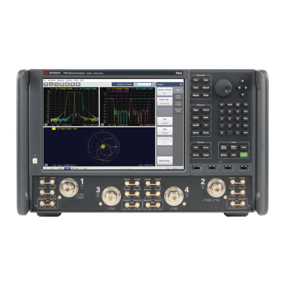
- Page 80 PNA-X, N522x, and N523x Front-Panel Tour Click on an area of the image to learn more. See Also PNA-X Models/Options N522xA Models/Options N523x Models/Options Display area Rear-panel Tour PNA-X and N522xA N523xA Familiar Hardkey layout, similar to Agilent 8720 and 8753 Network Analyzers...
- Page 81 Back to the familiar layout, significantly different from legacy PNA models. Most measurement settings are made from the Stimulus Block and the Response Block. Fully functional Hardkey/Softkey selections consistent with Menu (mouse) selections Access ALL PNA settings from the front panel using hardkey/sofkeys or from the Menu using a mouse. Both methods are consistent;...
- Page 82 USB Hub This USB hub contains four USB ports to power your PNA peripherals. There are also four USB ports on the rear panel. Limitation: The total power consumption for all eight USB ports is limited to 4.0 amps. If this limit is exceeded, all USB ports are disabled until a device is removed and power consumption falls below the limit.
-
Page 83: Table Of Contents
Measurement Class More Meas Receivers Format Format Scale Scale Electrical Delay Phase Offset More Velocity Factor Media -Waveguide/coax Waveguide cutoff freq Display Display settings Arrangements (Overlay...) Windows (Managing) Measurement Setups Display Items Title Trace Status Freq Stimulus Marker Display Toolbars Tables Status Bar Hide Sofkeys... -
Page 84: Velocity Factor
Start Cal Cal Wizard Preferences Global Delta Match Correction Power Cal Source Cal Receiver Cal Manage Cals Cal Set Cal Type Cal Set Viewer Properties (must have a Cal ON) no idea what this is Port Ext Toolbar Interpolation Fixtures ON |Off Port matching lots more... - Page 85 Hard Key Invokes these Softkeys - Click to learn more Marker Markers Properties Delta Markers Discrete Type Coupled Functions Search Marker Search Memory Data/ Memory Math 8510 Mode Analysis Limit Lines Limit Test Global Pass/Fail Trace Statistics Gating Transform Windowing Coupling Distance Marker Equation Editor...
- Page 86 Hard Key Invokes these Softkeys - Click to learn more Freq Frequency Range Frequency Offset Mode Power RF Power level Power Slope Power and Attenuator settings Sweep Sweep Time Number of Points Sweep Type Sweep Setup Segment Table settings Trigger Trigger settings UTILITY Keys Performs global PNA operations.
- Page 87 SICL / GPIB Control Panel (Windows) System Z0 Power Meter Settings Millimeter Module Service Help Error Messages About NA User Key Touchscreen Preset Preset User Preset ENTRY Keys Hard Key Invokes these Softkeys Closes a dialog box and enters any values made in the dialog box. Cancel Closes a dialog box.
- Page 88 Decimal point Enters a decimal point to designate fractions of a whole number. Plus - Minus Toggles between a positive and negative value entry if it is the first key pressed in the entry. Knob Rotate to increase or decrease the value of the active entry. Navigation Keys These keys allow you to navigate through menus and dialog boxes and select choices from the active entry toolbar.
- Page 89 PNA-X and N522xA Rear Panel Differences between the PNA-X and N522xA Models N523xA rear-panel. Click image to learn more. 10 MHz Reference IN/OUT 10 MHz Reference Input When a 10 MHz external reference signal is detected at this port, it will be used as the instrument frequency reference instead of the internal frequency reference.
- Page 90 Limitation: The total power consumption for all eight USB ports is limited to 4.0 amps. If this limit is exceeded, all USB ports are disabled until a device is removed and power consumption falls below the limit. When first connected, Agilent ECal modules 8509x and N4431 draw significantly more current than other modules. Specifications.
- Page 91 Caution: LO OUT has more power than previous PNA models. See specifications IF Path Inputs Option 020 adds these connectors, which allow access to the PNA Receiver / IF paths. These are labeled A, B, C/R1, D/R2, R. For 2-port models, use A, B, R1, R2. For 4-port models, use A, B, C, D, R.
- Page 92 MEAS TRIG IN - When enabled, PNA is triggered by signals on this connector. Learn more. MEAS TRIG RDY When enabled, PNA outputs a 'READY' signal on this connector to other devices. Learn more. AUX TRIG 1&2 IN When enabled, PNA accepts signals on these connectors which indicates that the external devices is ready to be triggered.
- Page 93 Determine Your PNA's CPU Version (Internet connection required) Removable Hard Disk Drive Service Guide to learn how to remove the HDD. (Internet connection required) Preventing PNA Hard Drive Problems Last modified: 3-May-2012 Removed model references 19-Apr-2012 Updated RP image 28-Jun-2011 Added link to first time note 4-May-2011 Added N522x...
- Page 94 Powering the PNA ON and OFF The following is described in this topic: How to... Shutdown Turn OFF Autostart Notes During boot up of Windows or of the Network Analyzer application program, do NOT press keys on the front panel, rotate the RPG knob, or connect a USB device. Doing so MAY lead to a front panel lockup state. If the PNA front-panel keypad or USB ports are not responding, SHUTDOWN or RESTART the PNA.
- Page 95 Turn OFF PNA Autostart The PNA application (835x.exe) always starts automatically when power is turned ON. To cause the PNA to NOT Autostart, do the following: Minimize the PNA application. From Windows Explorer, navigate to and double-click the following file: C:/Program Files/Agilent/Network Analyzer/Service/Toggle_PNA_Autostart.
-
Page 96: Electrical Delay
Traces, Channels, and Windows on the PNA It is critical to understand the meaning of the following terms as they are used on the PNA. Traces Managing Channels Managing Windows Managing Other Quick Start topics Traces are a series of measured data points. - Page 97 How to Create a new trace How to Change the trace parameter How to display a custom trace title (separate topic) How to display a wide active trace (separate topic) How to Select a Trace A trace must be selected (active) before its trace settings can be changed. How to know which trace is Active? Using front-panel PNA Menu using a mouse...
- Page 98 How to Move a trace to a different window You can DRAG a trace from one window to another, or... Using front-panel PNA Menu using a mouse [softkey] buttons HARDKEY Select the trace to move. Right-click the Trace Status label, then click Move Trace.
-
Page 99: Trace Status
With Trace Max ON, select a different trace from the Traces softkeys to make that trace visible. To make all traces visible again select Trace Max OFF Channels contain traces. The PNA can have up to 200 independent channels (32 before A.09.00) Channel settings determine how the trace data is measured . - Page 100 Turn ON | OFF Channel dialog box help Both the Turn ON and Turn OFF dialogs work the same. Select a channel, then click OK. Only ONE channel can be selected When turning ON a channel, the new channel is always the Standard Measurement Class with an S11 trace.
- Page 101 PNA-X shows the window number in the lower-left corner of the window. The following shows window 5. Managing Windows How to make various window settings New, Close, Tile, Cascade, Minimize, Maximize Using front-panel PNA Menu using a mouse [softkey] buttons HARDKEY Press R Click Response...
- Page 102 Close Window dialog box help Select a window, then click OK. The remaining windows are tiled. Only ONE window can be selected. Traces contained in a closed window are deleted. Note: To EASILY close a window, right-click in the window (away from a trace) then select Close Window. Customize the PNA screen to learn how to make other window settings.
- Page 103 Quick Start Dialog Beginning with A.09.50, you can optionally see the following dialog when the PNA is Preset. Click a button to quickly setup the measurement type. The buttons appear ONLY if that option is installed on the PNA. Click the image to learn more about each measurement. Clear Show on Preset to no longer see this dialog when Preset.
- Page 104 Bandwidth. Learn more about S-parameter measurements. Creates Sdd11 and Sdd21 measurements in a single channel and window. Differential Option Required: None Enter Start/Stop frequency, Power Level, and Bandwidth. Learn more about Differential (Balanced) measurements. Creates an S11 measurements and enables Time Domain. Time Domain Option Required:...
- Page 105 Power Option Required: None Enter Start/Stop frequency, Power Level, and Bandwidth. Learn more about Unratioed Receiver measurements. Creates a power sweep while viewing R1, B, and S21 measurements in a single channel and window. This allows you to view the DUT input power (R1), output power (B), and DUT gain (S21).
- Page 106 Noise Figure Option Required: 028/029 Enter Start/Stop frequency, Power Level, and Noise Bandwidth. Learn more about Noise Figure measurements. Creates a power sweep while viewing S21 (gain) with Compression Markers. Compression Option Required: None Enter Start/Stop power, Frequency, and Bandwidth. Learn more about Gain Compression Markers.
- Page 107 Mixer Option Required: 082/083 Enter Input, LO, and Output Frequencies and configuration. Learn more about SMC Measurements Creates an CompOut21 (Gain Compression) measurement. Compression vs Frequency Option Required: Enter Start/Stop frequency, and Start/Stop Power Level. Learn more about Gain Compression App Last modified: 23-Sep-2011 New topic...
- Page 108 Basic Measurement Sequence The following process can be used to setup all PNA measurements: Step 1. Set Up Measurements Reset the analyzer, create a measurement state, and adjust the display. Step 2. Optimize Measurements Improve measurement accuracy and throughput using techniques and functions. Step 3.
- Page 109 Frequency Blanking For security reasons, you can prevent frequency information from appearing on the PNA screen and printouts. How to set Frequency Blanking Using front-panel Using a mouse with PNA Menus [softkey] buttons HARDKEY Press Click Utility SYSTEM then [Security] then System then Security Security Setting dialog box help...
- Page 110 All tables All toolbars All printouts External sources - See Also: Preference to Deactivate External Devices on Preset. Note: Frequency Blanking is fully supported ONLY on Agilent MXG sources with option 006. On MXG models without option 006 and all PSG models, the window state is turned OFF. When the “local” button is clicked on the source, then frequency is re-displayed.
- Page 111 Re-displaying frequency information When in Low security level, do any of the following: Revisit this dialog box and select None Perform an instrument preset Recall an Instrument State/Cal Set with security level of None. When in High or Extra security level, do any of the following: Perform an instrument preset Recall an Instrument State/Cal Set with security level of None.
- Page 112 Internal Second Source The following PNA models include an internal second source. Model Total # of Ports PNA-X Opt 224 ALL PNA-X models N522xA Opt 400's How to use the second source Set frequency using the Frequency Offset Opt 080 dialog.
- Page 113 Source 1 power is available at Port 1 OR Port 2; NOT at both ports simultaneously. Source 2 (SRC 2) power is available at Out 1 AND Out 2; BOTH ports simultaneously. Other routing configurations are possible using the RF Path Configurator.
- Page 114 Networking and Connecting the PNA The PNA as a PC PNA User Accounts and Passwords Drive Mapping Connecting the PNA to a PC Easy versus Secure Configuration Changing Network Client Using VNC to Control the PNA User Interface GPIB / COM Programming Configure for COM/DCOM Programming Configure for GPIB, SCPI, and SICL Controlling External Devices...
- Page 115 PNA Preferences PNA preferences are settings that survive a Preset or PNA Shutdown. PNA Preferences are listed on this page with links to locations that provide more information. How to set PNA Preferences Using front-panel PNA Menu using a mouse [softkey] buttons HARDKEY Press S...
- Page 116 Selected Trace is wider. The selected trace is the narrow, default size. Selected Trace is wider. The active (selected) trace is always wider. Selected trace changes width briefly. The selected trace does NOT change width briefly. Selected trace changes width briefly. This setting only affects calibrations performed using SCPI or COM.
- Page 117 Memory: Data Math 8510 Mode Standard PNA data processing chain. Memory: Data Math 8510 Mode Simulate the Agilent 8510 data processing chain as it pertains to Trace Math and Memory. Learn more. Meas: Mathematical offset for receiver attenuation The reported test port receiver power is mathematically offset by the amount of receiver attenuation.
- Page 118 For SCPI behavior only. Learn more. Report source unleveled events as errors Source unleveled events are reported as errors. Report source unleveled events as errors Source unleveled events are NOT reported as errors. Ext Device: de-activate on PRESET and recall. External devices are de-activated when the PNA is Preset or when a Instrument State is recalled.
- Page 119 The More buttons launch dialogs that contain predefined preferences: Define Data Saves - While not explicitly called Preferences, all of these settings survive a shutdown. Learn more. User Preset Specify the Instrument State file that the PNA will use when Preset. Learn more.
- Page 120 5-Apr-2012 Added math to attn note 22-Feb-2012 Added note to Ext trigger for cals 29-Dec-2011 Added checkbox images 10-Sep-2010 Added Cal windows 26-Aug-2010 Added overload preferences 24-Mar-2010 Removed Error messages button 31-Jul-2009 Added External Device, primary FOM, draw failed segments, Power Limit, disp colors, print colors (9.0) 6-Feb-2009 Added new Cal set selection...
- Page 121 Using VNC to Control the PNA User Interface VNC (Virtual Network Computing) allows you to control the User Interface of a PNA from any PC. The PNA display appears on the connected PC display. Mouse and keyboard control can occur from both the PNA and PC, although not simultaneously.
- Page 122 LXI-1.1 and VXI-11.3 Compliance PNA-X, N522x, and PNA-C models that were shipped with PNA version A.08.20 or higher are LXI-1.1 and VXI-11.3 compliant. LXI-1.1 Compliance A PNA is LXI-1.1 compliant if the A PNA is LXI-1.1 compliant if the logo appears on the PNA splash screen when the PNA application starts. logo appears on the PNA splash screen when the PNA application starts.
- Page 123 LAN Status dialog box help Indicator Shows the current status of the LAN connection. NORMAL - Indicates that the PNA LAN is ready for communication. IDENTIFY - Indicates that a remote computer has invoked an LXI identification operation on the PNA using the web-based interface or LXIDeviceIDState COM property.
- Page 124 Type the log on User Name and Password You will see the following welcome screen with connection links. Last modified: 4-May-2011 Added N522x 1-Apr-2011 Updated to include VXI...
- Page 125 Using Help Help Rev. September 18, 2012 PNA Rev. A.09.80 © Agilent Technologies, Inc. This topic discusses the following: PNA Documentation Printing Help Copying Help to your PC Launching Help Navigating Help Searching Help Help Languages Glossary Dialog Boxes Documentation Warranty...
- Page 126 the Print icon at the top of the PNA Help window. Copying Help to your PC With the Help system on your PC, you can read about the PNA while away from it. You can also Copy and Paste programming code from this Help system directly into your programming environment. The Help file is located on your PNA hard-drive at C:/ Winnt/ Help/ PNAHelp.chm.
- Page 127 topic. Hide or show the navigation pane Locate the topic in the table of contents Back to topic visited previously Forward again if Back was clicked Go to the Home page. Print the topic pane. Navigation Pane Click the following tabs in the Navigation Pane to access information in the Help system: Table of Contents Tab Index Tab Search Tab...
- Page 128 Click tab to select Table of Contents. Click a book to access related topics. Click to display a topic. Right click to access menu. Click to display specifications Click to display glossary Index Tab The index tab allows you to type a keyword and go to only the most applicable topics. Click tab to select index.
- Page 129 Use Boolean operators to define a relationship between two or more search words. Search for Example Results will show topics containing: Two words in the same topic response AND Both the words "response" and "calibration". calibration Either of two words in a topic response OR Either the word "response"...
- Page 130 Help Languages Beginning with PNA Rev A.08.00, PNA Help is offered in English ONLY. Glossary Glossary holds definitions of words, in alphabetical order. Note: Click on a word in green text throughout Help to see the glossary definition. Dialog Boxes...
- Page 131 Documentation Warranty THE MATERIAL CONTAINED IN THIS DOCUMENT IS PROVIDED "AS IS," AND IS SUBJECT TO BEING CHANGED, WITHOUT NOTICE, IN FUTURE EDITIONS. FURTHER, TO THE MAXIMUM EXTENT PERMITTED BY APPLICABLE LAW, AGILENT DISCLAIMS ALL WARRANTIES, EITHER EXPRESS OR IMPLIED WITH REGARD TO THIS MANUAL AND ANY INFORMATION CONTAINED HEREIN, INCLUDING BUT NOT LIMITED TO THE IMPLIED WARRANTIES OF MERCHANTABILITY AND FITNESS FOR A PARTICULAR PURPOSE.
- Page 132 Help - About Network Analyzer Click Help, then About Network Analyzer to learn the following about your PNA: Model number (see list of PNA models) Frequency range Serial number Installed options (Learn how to install software options) Application Code (firmware) Version Hard Disk Drive Version System CPU Version - Learn more...
- Page 133 Computer Name - Learn more. This is also reported on the LAN Status / LXI Compliance dialog. DSP Version changes For PNA-X, the DSP board number along with the FPGA version, provides access to the following features or causes the following settings to change: FPGA Changes Board...
- Page 134 Preset the PNA When you Preset the PNA, it is set to known, or preset conditions. You can use the factory default preset conditions, or define your own User Preset conditions. Preset (Default) Conditions User Preset Conditions See other 'Setup Measurements' topics Preset Default Conditions How to Preset the PNA Tip: Press the Preset button to start the PNA application if it is not already running.
- Page 135 User Preset dialog box help With a User Preset saved and enabled, when the PNA is Preset, the User Preset settings are recalled instead of the factory default settings. Calibration data is NOT recalled with a User Preset. Learn more about instrument state settings.
-
Page 136: Measurement Class
Measurement Classes Measurement Classes are categories of measurements that can coexist on a channel. What are Measurement Classes How to assign a Measurement Class to a Channel Measurement Class Dialog Box Help See other 'Setup Measurements' topics What are Measurement Classes The following table shows the Measurement Classes currently available for the PNA. - Page 137 Measurement Class dialog box help Measurements in a measurement class can NOT coexist in a channel with a measurement of a different measurement class. Select a measurement class for the active channel or new measurement channel. The Standard measurement class contains S-Parameters. Balanced parameters, and Receiver measurements.
- Page 138 29-Jul-2011 Several small DM changes 6-Aug-2010 Added Confirm changes 1-Jul-2010 Added Standard vs Application 22-Mar-2010 Updated dialog image 3-Sep-2008 Removed legacy content 18-Jun-2007 MX New topic...
- Page 139 Measurement Parameters This topic contains the following information: S-Parameters (pre-selected ratios) Ratioed (choose your own ratio) Unratioed Power (absolute power) How to Select a Measurement Parameter Learn about Balanced Measurements See other 'Setup Measurements' topics S-Parameters S-parameters (scattering parameters) are used to describe the way a device modifies a signal. For a 2-port device, there are four S-Parameters.
- Page 140 When the source goes into port 2, the measurement is said to be in the reverse direction. The analyzer automatically switches the source and receiver to make a forward or reverse measurement. Therefore, the analyzer can measure all four S-parameters for a two-port device with a single connection. See the block diagram (including receivers) of your PNA.
- Page 141 Ratioed Measurements Ratioed measurements allow you to choose your own ratio of any two receivers that are available in your PNA. S- parameters are actually predefined ratio measurements. For example S11 is A/R1. The following are common uses of ratioed measurements: Comparing the phase between two paths of a device.
- Page 142 How to CHANGE the active trace The only measurements that can be selected are those in the same measurement class as is currently assigned to the channel. To select a measurement other than these, first select the appropriate measurement class to a new or existing channel. Learn how.
- Page 143 Receivers Select receivers to make Ratioed and Unratioed (absolute power) measurements. Learn more about receiver measurements. Ratioed Check Activate to create or change a measurement. Select a receiver for the Numerator, select another receiver for the Denominator, then select a source port for the measurement. The Source port is ALWAYS interpreted as a logical port number.
- Page 144 Receiver Notation With PNA 6.2, receivers can be also selected using logical receiver notation. This "8510-style" notation makes it easy to refer to receivers with an External Test Set connected to the PNA. aN - Reference receiver for logical port N bN - Test port receiver for logical port N For example: For Ratioed measurements: "b12/a1"...
- Page 145 Balanced DUT Topology / Logical Port mappings dialog box help See this dialog for Integrated True Mode Stimulus Application (iTMSA). Create or edit DUT Topology and Logical Port Mapping. A Logical Port is a term used to describe a physical PNA test port that has been remapped to a new port number.
- Page 146 Learn about Logical Port mapping when using an External Test Set. Learn more about Balanced Measurements Balanced parameters can be saved to SNP files. Learn more. Last modified: 16-Mar- Minor edits to notation 2012 29-Apr-2011 Added images 2-Mar-2010 Link to SNP files 10/11/06 Added new UI 9/19/06...
- Page 147 Frequency Range Frequency range is the span of frequencies you specify for making a device measurement. How to Set Frequency Range Zoom CW Frequencies Frequency Resolution Frequency Band Crossings See other 'Setup Measurements' topics How to set Frequency Range There are two ways to set the frequency range: Specify the Start and Stop frequencies of the range.
- Page 148 Frequency Start/Stop dialog box help Start Specifies the beginning frequency of the swept measurement range. Stop Specifies the end frequency of the swept measurement range. Frequency Center/Span dialog box help Center Specifies the value at the center of the frequency sweep. This value can be anywhere in the analyzer range.
- Page 149 How to Zoom in a measurement window Left-click the mouse or use a finger, then drag across a portion of a trace. Release the mouse or lift the finger and the following menu appears: Select from the following: Zoom - changes the channel stimulus settings to the left and right border values of the Zoom selection Zoom xy - changes the channel stimulus settings as above.
- Page 150 How to set CW Frequency Sweep Type to CW Time or Power. You can also set CW frequency from within the Sweep Type dialog box. Using front-panel PNA Menu using a mouse [softkey] buttons HARDKEY Press F Click Stimulus then [CW] then Frequency then CW Frequency CW Frequency dialog box help...
- Page 151 PNA-X Models N522xA Models N523xA Models PNA-X (Band Stop Frequencies) N5241A and N5242A Band Freq Band Freq Band Freq (GHz) (GHz) (GHz) Reserved .396 8.50 Reserved .500 10.664 .014 .628 12.00 .019 1.00 12.80 .027 1.50 13.51 .038 2.00 15.40 .053 3.00 16.00...
- Page 152 Band Freq Band Freq Band Freq Band Freq (GHz) (GHz) (GHz) (GHz) Reserved .396 8.50 27.008 Reserved .500 10.664 32.00 .014 .628 12.00 36.50 .019 1.00 12.80 40.50 .027 1.50 13.51 42.656 .038 2.00 15.40 43.50 .053 3.00 16.00 46.20 .075 3.20 19.00...
- Page 153 3.200 24.00 64.00 4.000 26.50 67.00 5.330 27.00 70.00 N522xA Models (Band Stop Frequencies) N5221A and N5222A Band Freq Band Freq (GHz) (GHz) Reserved 6.752 .010 .053 10.664 .175 13.51 .250 15.40 .500 16.0 20.0 21.328 24.0 27.0 5.332 N5224A and N5225A...
- Page 154 Band Freq Band Freq Band Freq (GHz) (GHz) (GHz) Reserved 6.752 32.00 Reserved 8.00 40.50 .053 10.664 42.656 .175 13.51 43.50 .250 15.40 46.20 .500 16.00 48.00 1.000 19.00 50.20 2.000 20.00 3.000 21.328 3.200 24.00 4.000 26.50 5.332 27.008 N5227A Band Freq...
- Page 155 3.200 24.00 64.00 4.000 26.50 67.00 5.332 27.008 70.00 N523xModels See N523x Freq ranges. N5231A, N5232A, N5239A Band Freq Band Freq (GHz) (GHz) Reserved 5.33 .000425 6.75 .0012 8.00 .0075 10.07 .025 13.50 .050 16.00 1.00 16.70 2.00 20.01 3.00 4.00 N5234A, N5235A Models...
- Page 156 Band Freq Band Freq Band Freq (GHz) (GHz) (GHz) 10.66 30.80 .010 13.51 31.50 .025 15.40 32.00 .050 16.00 40.00 1.00 20.00 40.56 2.00 20.26 42.00 3.00 21.33 48.00 4.00 24.00 50.00 5.332 26.00 6.752 27.01 8.00 Last modified: 7-May-2012 Added N523x series 21-Jul-2011 Added N522xA series...
- Page 157 Power Level Power level is the power of the PNA source at the test ports. How to make Power Settings Power Dialog Power and Attenuator Dialog Source Unleveled Setting Independent Port Power Optimum Attenuation Value Receiver Attenuation Power ON and OFF during Save / Recall, User Preset, and Preset Power ON and OFF during Sweep and Retrace See other 'Setup Measurements' topics Power Settings...
- Page 158 Power dialog box help Basic control of PNA source power for a specific port. advanced control of source power and attenuation. Power On (All Channels) Check to enable source power for all channels. Only turns power ON if channel power setting is ON or Auto. See Advanced Power.
- Page 159 Power and Attenuators dialog box help Defines and controls the PNA source power and attenuation for the active channel. Beginning with PNA Rev. 7.21, external sources can be controlled from this dialog. Learn more. Power On (All Channels) Check to enable source power for all channels. Only turns power ON if channel power setting is ON or Auto.
- Page 160 Start / Stop Power Available ONLY when sweep type is set to Power Sweep. Set the start and stop power values of a power sweep. Learn more about Power Sweep. In PNA release 6.04 you can specify whether to maintain source power at either the start power or stop power level at the end of a power sweep.
- Page 161 Leveling Mode Internal Standard ALC leveling. Power level within an attenuator setting is limited to the ALC Range. See Source Unleveled. Receiver Rx Select a Reference receiver to use for leveling the source. Learn more. Open Loop (Used during pulse conditions with the internal source modulators). NOT available on N523x models.
- Page 162 Power Sweep Range (ALC) = -17 dB For this frequency range the specified power range is calculated as: Max = -8 dBm Min = (-8)-(17) = -25 dBm When using Source Attenuators: with 10dB of attenuation, this becomes -18 dBm to -35 dBm with 20dB of attenuation, this becomes -28 dBm to -45 dBm, and so forth.
- Page 163 Each range has a total specified span ( 25 dB in the following Attenuation Values graphic ). The optimum setting is the middle of the range. This range provides the best accuracy and performance of the source leveling system. The optimum ranges are the blue regions in the following graphic. An attenuator setting can be selected manually or automatically.
- Page 164 Receiver Attenuators are offered as an option. Learn more. Type or select independent attenuation values for each receiver. Receiver A is at Test Port 1 Receiver B is at Test Port 2 Receiver C is at Test Port 3 Receiver D is at Test Port 4 Receiver Attenuation is used to protect the PNA test port receivers from damage or compression.
- Page 165 Power ON and OFF during Save / Recall, User Preset, and Preset To protect your DUT from being inadvertently powered ON, the following RF Power ON/OFF settings occur: Instrument State Save/Recall If power is OFF when an instrument state is saved, then power will always be OFF after the instrument state is recalled.
- Page 166 power is turned back ON before arming for the next trigger. Hold mode - Power can be ON or OFF depending on when and how Hold mode is entered. However, power can be immediately turned OFF manually or remotely. Caution: Avoid expensive repairs to your PNA. Read Electrostatic Discharge Protection.
- Page 167 Receiver Leveling Receiver Leveling adjusts the source power until the measured receiver power is equal to the Port Power. In this topic: Overview Receiver Leveling Process Features and Limitations How to make Receiver Leveling settings Receiver Leveling dialog box help Initial Power Selection See other 'Setup Measurements'...
- Page 168 Receiver Leveling can be used with most sweep types, including Segment sweep and Power sweep. See Wide Power Sweep with Receiver Leveling. Receiver Leveling is ALWAYS enabled for the controlled source when Phase Control (Opt 088) is enabled. Receiver Leveling is available for standard S-parameter measurements and with FCA, GCA, and applications.
- Page 169 Receiver Leveling dialog box help Learn about Receiver Leveling (scroll up). Define Controlled Source (Port) Each source port to be leveled is configured individually. Select a source to be configured for receiver leveling. Choose from: Port 1, Port 2, Port 3, Port 4, or any active external RF or DC source. Learn more about External Devices.
- Page 170 "B" or 'b2". Learn about Receiver Notation. When Phase Control is enabled, the ratioed receivers used in Phase Control are selected and can NOT be changed. However, the Reference Source CAN also be selected for Receiver Leveling. For Ext Device type, choose a configured PMAR device. Level when this RF source is turned ON: The Controlled Source is selected automatically and can NOT be changed.
- Page 171 When checked, PNA internal leveling hardware is used. (Recommended) When cleared, Open Loop hardware is used. NOT available on N523x models. Enable Safe Mode while leveling To protect your DUT, these settings control the extent to which the source power will be changed to achieve the port power as measured at the reference receiver.
- Page 172 Where: P Init = the initial power for the iteration process. P Final = the final power setting from the previous leveled sweep. P Min = the minimum controlled source output level as specified in the Receiver leveling setup. P Max = the maximum controlled source output level as specified in the Receiver leveling setup. P Target = the target power level for the selected leveling receiver.
- Page 173 Sweep Settings A sweep is a series of consecutive data point measurements taken over a specified sequence of stimulus values. You can make the following sweep settings: Sweep Type Linear / Log Power Sweep CW Time Segment Sweep Phase Sweep Time Sweep Setup Stepped vs Analog Fast Sweep...
- Page 174 Sweep Type dialog box help Note: Sweep Settings are not applied until either OK or Apply is pressed. Channel The active channel when Sweep Type was selected. Sweep settings will be applied to this channel. Sweep Type Linear Frequency Sets a linear frequency sweep that is displayed on a standard grid with ten equal horizontal divisions.
- Page 175 Points Sets the number of data points that the PNA measures during a sweep. Range: 2 to 20001.(Default is 201). Segment Sweep Sets the PNA to sweep through user-defined sweep segments. Learn how to make these settings. Independent Power Levels Check to set the source power level for each segment. Test port uncoupling is also allowed.
- Page 176 but triggering can be performed using single or group triggering. Learn more. The remaining power settings apply in power sweep mode: Test Port Power setting is not available. Port Power can be coupled or uncoupled. Attenuator Control is always Manual. Power Slope (dB/GHz) is ignored (output frequency is CW).
- Page 177 How to make segment sweep settings Using front-panel PNA Menu using a mouse [softkey] buttons HARDKEY Press S Click Stimulus WEEP then [Sweep Type] then Sweep then Sweep Type Insert Segment - adds a sweep segment before the selected segment. You can also click the "down" arrow on your keyboard to quickly add many segments.
- Page 178 Then click the box and type a value or double-click the box and select a value. Note: If the following are NOT set, the entire sweep uses the channel IFBW, Power, and Time settings. IFBW Sets the IF Bandwidth for the segment. POWER Sets the Power level for the segment.
- Page 179 With X-Axis Point Spacing Arbitrary Segment Sweep This feature allows arbitrary frequencies to be entered into the segment sweep table. With this capability, segments can have: overlapping frequencies. the stop frequency less than the start frequency (reverse sweep). How to enable Arbitrary Segment Sweep On the Sweep Type dialog box, click Segment Sweep...
- Page 180 How to set Sweep Time Using front-panel PNA Menu using a mouse [softkey] buttons HARDKEY Press S Click Stimulus WEEP then [Time] then Sweep then Sweep Time Time dialog box help Sweep Time Specifies the time the PNA takes to acquire data for a sweep. The maximum sweep time of the PNA is 86400 seconds or 1 day.
- Page 181 the indicator is stopped (point sweep mode) the source has already stepped to the next data point. Sweep Setup How to make Sweep Setup settings Using front-panel PNA Menu using a mouse [softkey] buttons HARDKEY Press S Click Stimulus TIMULUS then [Sweep] then Sweep then [Sweep Setup]...
- Page 182 Source Power Correction is ON unless doing CW measurement. When more than one source is turned ON (multisource PNA models). When step mode is a faster way to take the data. For all measurements. For all ADC measurements. For all MMwave measurements.
- Page 183 25-Jun-2012 Point sweep edit (JE) 3-May-2012 Edited for N523x models 6-Feb-2012 Edited Alternate sweep 27-Oct-2010 Added Phase Sweep and Time diag (9.30) 26-Aug-2010 Added link to Wide Power Sweep 1-Mar-2010 Sweep Delay and Point sweep now on C models 28-Sep-2009 Added segment frequency resolution note.
- Page 184 Trigger A trigger is a signal that causes the PNA to make a measurement sweep. The PNA offers great flexibility in configuring the trigger function. View the interactive Trigger Model animation to see how triggering works in the PNA. How to Set Trigger Source Scope Channel Settings...
- Page 185 Trigger Setup dialog box help View the interactive Trigger Model animation to see how triggering works in the PNA. Trigger Source These settings determine where the trigger signals originate for all existing channels. A valid trigger signal can be generated only when the PNA is not sweeping. Internal Continuous trigger signals are sent by the PNA as soon as the previous measurement is complete.
- Page 186 Groups The channel accepts only the number of trigger signals that is specified in the Number of Groups text box, then goes into Hold. Before selecting groups you must first increment the Number of Groups text box to greater than one. Number of Groups Specify the number of triggers the channel accepts before going into Hold.
- Page 187 Trace Sweep Order For ALL Trigger Modes, trigger signals continue in the same channel until all traces in that channel are complete. Triggering then continues to the next channel that is not in HOLD. Traces within each channel are always swept in the following order: Traces are swept sequentially in source-port order.
- Page 188 External and Auxiliary Triggering External and Auxiliary triggering are both used to synchronize the triggering of the PNA with other equipment. Note: When an External Source is configured as an External Device, the PNA automatically controls all trigger settings. Do NOT make additional trigger settings. Learn more.
- Page 189 See how to access the Trigger Dialog Meas Trig RDY and Meas Trig IN MEAS TRIG connectors are located on the PNA rear-panel. These signals can be used when the PNA is communicating with a slow mechanical device. A material handler is very mechanical and takes a relatively long time to load and discharge parts.
- Page 190 Meas Trig IN BNC Handler I/O Pin 18 Level / Edge High Level The PNA is triggered when it is armed (ready for trigger) and the TTL signal at the select input is HIGH. Low Level The PNA is triggered when it is armed (ready for trigger) and the TTL signal at the select input is LOW.
- Page 191 Aux Trig 1 - Aux Trig 2 dialog box help See how to access the Trigger Dialog Note: When an External Source is configured as an External Device, the PNA automatically controls all trigger settings. Do NOT make additional trigger settings. Learn more.
- Page 192 AFTER the measurement is complete. When communicating ONLY with an external source, the Aux Trig OUT signal should be sent AFTER the measurement is complete to indicate that the external source can setup for the next measurement. Dialog Settings The Aux Trig 1 and Aux Trig 2 tabs are identical. Two pair of connectors are available to allow two external devices to be controlled simultaneously.
- Page 193 Delay Time that the PNA waits after receiving the Handshake input before data acquisition begins. See Also See how to use these connectors to synchronize with External Sources. Pulse Triggering Note: Beginning with PNA Rev 6.0, Guided and Unguided Calibration CAN be performed in External Trigger mode.
- Page 194 Trigger Source Speedometer Internal Manual Trigger Scope Global Channel Continuous Continuous Continuous Groups Groups Groups Single Single Single Hold Hold Hold Point Point Point About the trigger model Read Text description of triggering behaviors. This model does not include the new Sweep trigger mode.
- Page 195 Data Format A data format is the way the PNA presents measurement data graphically. Pick a data format appropriate to the information you want to learn about the test device. How to set Format Rectangular (Cartesian) Display Formats Polar Smith Chart See other 'Setup Measurements' topics How to set the Display Format Using front-panel...
- Page 196 Format dialog box help Log Mag Phase / Unwrapped Phase Group Delay Smith / Inverse Smith Chart Polar Linear Mag Real Imaginary Rectangular Display Formats Seven of the nine available data formats use a rectangular display to present measurement data. This display is also known as Cartesian, X/Y, or rectilinear.
- Page 197 Deviation from Linear Phase Unwrapped Phase Same as Phase, but without 180 degree wrapping. Note: Phase is unwrapped by comparing the phase from one data point to the next. If the phase difference between two points is greater than 180 degrees, or if the phase of the first data point is greater than 180 degrees from DC, than the phase measurement is probably NOT accurate.
- Page 198 Displays only the real (resistive) portion of the measured complex data. Can show both positive and negative values. Y axis: Unitless Typical Measurements: time domain auxiliary input voltage signal for service purposes Imaginary Format Displays only the imaginary (reactive) portion of the measured data. Y - axis: Unitless Typical Measurements: impedance for designing matching network...
- Page 199 ±180°, and -90° correspond to the top, left-most, and bottom positions on the polar display, respectively. Smith Chart Format The Smith chart is a tool that maps the complex reflection coefficient ( ) to the test device's impedance. In a Smith chart, the rectilinear impedance plane is reshaped to form a circular grid, from which the series resistance and reactance can be read (R + jX).
- Page 200 Every point on the Smith Chart represents a complex impedance made up of a real resistance (r) and an imaginary reactance (r+-jX) The horizontal axis (the solid line) is the real portion of the impedance - the resistance. The center of the horizontal axis always represents the system impedance.
- Page 202 Scale The Scale, Reference Level and Reference Position settings (along with Format) determine how the data trace appears on the PNA screen. Scale, Reference Level and Position Scale Coupling Magnitude Offset See other 'Setup Measurements' topics Scale, Reference Level and Position The Scale, Reference Level and Reference Position settings (along with format) determine how the data trace appears on the PNA screen.
- Page 203 Scale dialog box help Note: Beginning with PNA Rev. 9.0, the scale settings are set to couple with other traces in each window. The following settings assume that Scale Coupling is set to OFF. Learn more about Scale Coupling. Scale Per Division Sets the value of the vertical divisions of a rectangular display format.
- Page 204 increments. Scale Coupling With Scale Coupling enabled, traces that have the same format will have the same Scale, Reference Level, and Reference Position. You can choose to couple the scale of traces that are in the same window, couple the scale of all traces in all windows, or to have NO coupling.
- Page 205 Scale Coupling dialog box help Allows traces that share the same format to have the same Scale, Reference Level Reference Position. Coupling Method Off - No coupling. Traces are scaled individually. Default setting. Window - All traces with the same format in each selected window share the same scale settings. All - All traces in ALL selected windows with the same format share the same scale settings.
- Page 206 How to set Magnitude Offset Using front-panel PNA Menu using a mouse [softkey] buttons HARDKEY Press S Click Response CALE then [More] then Scale then [Magnitude Offset] then Magnitude Offset Magnitude Offset dialog box help The Magnitude offset setting affects only the active trace. Offset Offsets the entire data trace by the specified value.
- Page 207 Pre-configured Measurement Setups Pre-configured setups for NEW measurements Pre-configured arrangements for EXISTING measurements Before reading this topic, it is important to understand Traces, Channels, and Windows in the PNA. See other 'Setup Measurements' topics Pre-configured Setups for NEW Measurements Each of the following setups creates new traces. Existing traces and their settings will be lost, unless you first save them.
- Page 208 Arranging Existing Measurements The following arrangements place EXISTING measurements into pre-configured Window arrangements using a sort algorithm. How to select an Existing measurement arrangement Using front-panel PNA Menu using a mouse [softkey] buttons HARDKEY Press D Click Response ISPLAY then [Layout] then Display then choose from the following...
- Page 209 Split 3x This configuration places all existing traces in three windows, two on top and one below. Quad 4x This configuration places all existing traces in four windows, one window in each screen quadrant. Sort Algorithm The sort algorithm for the Arrange Windows feature is designed to: Divide traces among windows based on their properties Group traces with common properties The algorithm sorting is based on the following trace properties, in order of priority:...
- Page 210 21-Jul-2011 New menu picks 3-Sep-2008 Removed legacy content 9/27/06 MX Added UI 9/12/06 Added link to programming commands...
- Page 211 PNA-X RF Path Configurator Allows you to configure hardware components that are available with selected PNA-X options. N522xA models do NOT have the RF Path Configurator. How to access Path Configurator Using [softkey] buttons: PNA Menu using a mouse: HARDKEY Press Click Trace/Chan TRACE...
- Page 212 Path Configuration dialog box help Noise Figure tab of the Path Configuration. Note: With selected PNA-X options, pulse modulation is available ONLY on OUT1 of Src 1 and Src 2. block diagram. Different paths can be configured for each channel. Configuration Select, store, and delete factory configurations or user-defined configurations.
- Page 213 Electronic switches are orange on the path configuration dialog. These switches do not make noise when being thrown. Mechanical switches are blue. The channel is not sweeping. The following selections do NOT throw switches, but simply indicate how to connect jumper cables by drawing red lines on the dialog: Combiner (Normal/Reversed) Port 2 Source (Src2 OUT1/Src1 OUT2)
- Page 214 so the highest possible output power is required. Source 1, routed through the coupled path of the combiner, is used for S-parameter measurements, so a small signal is sufficient. These two signals are combined but the frequencies are usually offset. See Also Configuration for High-power measurements Last modified:...
- Page 215 Source Phase Control (Opt 088) Option 088 allows you to control the phase of a PNA source or an external source. Two sources are required. Overview Features and Limitations Phase Control Use-Cases How to make Phase Settings Active Load Pull Examples See other 'Setup Measurements' topics Overview The Source Phase Control feature provides a specific phase difference between two sources.
- Page 216 phase control, then do NOT calibrate all four ports. If other ports are calibrated, then even ports 1 and 3 may not yield acceptable results. After performing calibration, the phase is aligned and the power is accurate at the calibration plane. Features and Limitations Phase Control is allowed ONLY in a standard S-parameter...
- Page 217 How to make Phase Control settings: Using front-panel Using a mouse with PNA Menus [softkey] buttons HARDKEY Press S Click Stimulus WEEP then [More] then Sweep then [Phase Control] then More then Phase Control To perform a Phase Sweep: Press S Click Stimulus WEEP then [Sweep Type]...
- Page 218 Phase Control dialog box help Phase Specify any Fixed Phase setting. Start / Stop Phase Available when Sweep Type is set to Phase Sweep. Learn how. Enter the Start and Stop phase values in degrees. Phase Control Click in the port cell to be controlled, then choose from the following: Off - Phase is NOT set or controlled.
- Page 219 Select a port to set its phase control configuration This is the 'controlled' port. Referenced to Select a source port to be used as a phase reference for the controlled port. The two internal PNA sources are available ONLY at specific ports. These choices are limited for you on the Phase Control dialog.
- Page 220 other, then the phase measurement is considered settled. Max Iterations Sets the maximum number of background phase measurements to perform in order to achieve settling. If the phase is not sufficiently settled after these measurements, then the closest value is used.
- Page 221 If you continually see Phase leveling warning: power not settled, then on the Power and Attenuators dialog, clear Port Powers Coupled (independent port power), then add attenuation to the controlled port. This happens because of additional power being measured from both sources. Active Load Control with 2-Port 2-Source PNA-X Models Connect a rear-panel jumpers cable from J8 to J1.
- Page 222 Last Modified: 29-Aug-2012 Added EXG 9-Apr-2012 Edited allowed models 20-Dec-2010 MX New topic...
-
Page 223: Status Bar
Customize the PNA Screen You can customize your PNA screen by showing or hiding the following display elements. All of these selections are made from the PNA Response > Display menu. Status Bar Display Labels Marker Display (Separate topic) Tables Toolbars Data and Memory Trace Title Bars... - Page 224 Gating (On) IF Gating Enabled for Pulsed App: (G) Manual IF Filtering for Pulsed App: (F) Delay if invoked using Phase Offset, Electrical Delay, or Port Extensions. Loss if invoked using Magnitude Offset Port Extensions. GPIB status: Local (LCL), Remote Talker Listener (RMT), or System Controller (CTL). Error Status: (LVL, LCK, etc) Note: A second level status bar appears when using External Test Set Control...
- Page 225 How to display Toolbars Using front-panel PNA Menu using a mouse [softkey] buttons HARDKEY Press D Click Response ISPLAY then [Tables and Toolbars] then Display then [Toolbars] then Toolbars List of toolbars: Entry Toolbar Markers Measurement Sweep Control Stimulus Time Domain Port Extension All Off (NOT on sofkeys)
- Page 226 Marker functions: Delta Start/Stop Center/Span Tip: To use the Front Panel Knob to change marker position, first click the Stimulus field of the marker toolbar. Then turn the knob. Learn more about Markers Measurement Toolbar The measurement toolbar allows you to create a new trace for a desired S-parameter measurement in a current window or new window.
- Page 227 Change the Start / Stop times for both Transform and Gating More...launches the Time Domain Transform dialog box X Closes the toolbar The front panel Tab key steps through all of the settings on all of the toolbars on the display. If Tab does not work, press one of the Active Toolbar (color) keys.
- Page 228 Marker Table You can display a table of marker settings. These settings include the: Marker number Marker reference (for delta measurements) Frequency Time and Distance (for Time Domain measurements) Response Learn more about Markers Limit Line Table You can display, set up, and modify a table of limit test settings. These include: Type (MIN, MAX, or OFF) Beginning and ending stimulus values Beginning and ending response values...
- Page 229 How to show and hide Display items Using front-panel PNA Menu using a mouse [softkey] buttons HARDKEY Press D Click Response ISPLAY then [Labels] then Display then Labels Display Labels: Trace Status Trace Title Frequency Stimulus Grid SOLID | dotted Limit Test Results Limit Lines Title...
- Page 230 How to show/hide Trace Status Trace Title A Trace Title overwrites the Measurement Parameter in the Trace Status area, the Status Bar, and hardcopy prints. This title has priority over Equation Editor titles. The practical limit is about 70 characters if there is only one trace. Spaces are accepted but not displayed;...
- Page 231 Click in the window to make the window active. Click Response, then Display, then Labels, then Window Title. Click Enable, then type the trace title. Click Keyboard to type with a mouse. To remove the trace title, clear the Enable checkbox, or delete the text from the dialog entry. Frequency/Stimulus Frequency/stimulus information is displayed at the bottom of each window on the screen.
- Page 232 Learn more about Limit Lines How to show/hide Limit Lines and Results Data Trace and Memory Trace You can view or hide the active data or memory trace. Make a trace active by clicking the trace status button To view a memory trace you must first store a trace in memory. Click Trace, then Math / Memory, then Data =>...
- Page 233 How to minimize the Network Analyzer Application Using front-panel PNA Menu using a mouse [softkey] buttons HARDKEY Press D Click File ISPLAY then [Windows] then Minimize Application then [More] then [Minimize] To restore the PNA application, click the PNA application on the Windows taskbar. Last modified: 3-May-2012 Removed C models...
- Page 234 Copy Channels Copy channels allows you to make a duplicate channel of the same Measurement Class and with the same stimulus conditions as an existing channel. Why Copy Channels How to Copy Channels List of Channel Settings Note: Beginning with A.09.40, Copy Channels CAN be used with Applications, such as FCA, Gain Compression, or Noise Figure.
- Page 235 How to Copy Channels Using front-panel PNA Menu using a mouse [softkey] buttons HARDKEY Press Click Trace/Chan TRACE CHAN then [Channel] then Channel then [More] then Copy Channel then [Copy Channel[ Copy Channel dialog box help Copies an existing channel's settings to another channel. Measurement traces from the source channel are NOT copied.
- Page 236 The source channel is ALWAYS copied to the Active window. If you want the destination channel in a separate window, first create a compatible new measurement in a new window. Then make sure it is the Active window before you copy the channel into it. The measurement in the destination channel becomes the active measurement.
- Page 237 DC Source Control When a DC Source (power supply) is configured as an External Device, the new DC source can be controlled from the PNA using this dialog. Learn how to configure the DC Source as an External Device. How to start the DC Source Control dialog The DC Source Control dialog box The DC Limits dialog box Other Setup Measurements Topics...
- Page 238 Name Lists the names of the configured DC Sources. In the above image: AO1 and AO2 are internal PNA DC sources that are available on the rear-panel Power I/O connector (Pins 3 and 4). Learn more. MyDCSupply is the name of an external DC Source. Learn how to setup and configure an External DC Source and DC Meter.
- Page 239 DC Limits dialog box help Select the Minimum and Maximum voltages to which the specified DC sources can be set by the PNA. Last modified: 10-Jan-2012 New topic...
- Page 240 ADC Measurements The PNA is equipped with two ADC (Analog to Digital Converter) inputs on the rear-panel Power I/O connector (Pins 7 and 8). These ADC inputs can be used as measurement receivers and display measurements on the PNA screen. Analog Inputs (AI1 and AI2) can be used for measuring from -10V to +10V.
- Page 241 AOS1 or AOS2 - Output sense 1 or 2 AIG - Analog ground (PNA-X only) Denominator - NOT available (ONLY unratioed measurements) Source Port - The ADC receiver is measured when the specified source port is sweeping. Select None to always measure the ADC receiver.
- Page 242 2-Aug-2012 Added noise figure 21-Feb-2012 Added DAC outputs and DC source control 31-Aug-2009 Fixed two typos 23-Mar-2009 Added pin numbers 19-Apr-2007 MX New topic...
- Page 243 Undo/Redo Settings If you make an incorrect setting, you can quickly recover by selecting Undo. If you then incorrectly Undo a setting, you can Redo the undone setting. Undo and Redo applies ONLY to selected PNA settings. The Undo stack remembers 16 levels of Undo-able settings. How to Undo or Redo a setting Tips: Click or touch the Undo and Redo Icons:...
- Page 244 The Undo stack is cleared when programming commands are sent to the PNA. Clear Undo History To clear the Undo stack, press System, then Service, then Utilities, then Click Undo History. Undo and Security Undo/Redo is disabled with High and Extra security levels. Learn more.
-
Page 245: Measurement Setups
Close Window New Channel , new Window, and new Trace. Delete Trace Window Tile Change Layout (1x, 2x, 3x, 4x) Move Trace, Drag Trace Zoom XY, Zoom Out Full Autoscale All, Autoscale Scale, Reference Level, Reference Position Scale Coupling dialog Electrical Delay Phase Offset Measurement Setups dialog... - Page 246 Dynamic Range Dynamic range is the difference between the analyzer receiver's maximum input power and the minimum measurable power (noise floor). For a measurement to be valid, input signals must be within these boundaries. Increasing dynamic range is important if you need to measure very large variations in signal amplitude, such as filter bandpass and rejection.
- Page 247 Reduce the IF Bandwidth - learn more about Bandwidth. Segment sweep mode each segment can have its own IF bandwidth. For example, when measuring a filter: In the passband, the IF bandwidth can be set wider for a fast sweep rate, as long as high-level trace noise is kept sufficiently small.
- Page 248 See Also Front-panel Jumpers (image) Using the Front Panel Jumpers Specifications Last Modified: 5-Jan-2011 Removed old E835x std reference 5-Aug-2008 Combined several topics...
- Page 249 Number of Points A data point is a sample of data representing a measurement at a single stimulus value. You can specify the number of data points that the PNA measures across a sweep. (A "sweep" is a series of consecutive data point measurements, taken over a sequence of stimulus values.) The PNA sweep time changes proportionally with the number of points.
- Page 250 Number of Points dialog box help Specifies the number of data points that the analyzer gathers during a measurement sweep. You can specify any number from 1 to 32,001. The default value is 201. Note: Some measurement classes may have different maximum points limitations. Two data points are required for Time Domain.
- Page 251 Phase Measurement Accuracy You can increase the accuracy of phase measurements by using the following PNA features. Electrical Delay Phase Offset Spacing Between Frequency Points (Aliasing) See Also Port Extensions Comparing the PNA Delay Functions Phase Control Phase Coherent Measurements Learn more about Phase measurements Electrical Delay Electrical delay is a mathematical function that simulates a variable length of lossless transmission line.
- Page 252 Electrical Delay dialog box help Electrical Delay Specifies the value of delay added or removed, in Time or Distance. This compensates for the linear phase shift through a device. You can set the electrical delay independently for each measurement trace. Click the Step icon next to either Time or Distance to start the Step Size...
- Page 253 Step Size dialog box help Changes the step size that occurs when the Time or Distance up/down arrows are pressed on the Electrical Delay dialog. Auto Step Size is set to the default value. User Defined Enter a step size value, then click OK. This value remains the same when the units are changed.
- Page 254 Phase Offset dialog box help Phase Offset Type a value or use the up and down arrows to select any value up to 360 degrees. Learn about Phase Offset (scroll up) Spacing Between Frequency Points (Aliasing) The analyzer samples data at discrete frequency points, then connects the points, creating a trace on the screen. If the phase shift through a device is >180°...
- Page 255 Phase-Coherent Measurements Coherent phase means that the measurement does NOT have random phase. Coherent-phase measurements require the comparison of phase between two sources that are sweeping simultaneously. It also requires that two receivers are measuring the two sources simultaneously. This capability is available in the PNA-X using several applications: iTMSA (Opt 460) provides phase-coherent Balanced measurements.
- Page 256 Last Modified: 8-Apr-2011 Edited for accuracy 11-Nov-2010 MX New topic...
- Page 257 Electrically-Long Device Measurements A signal coming out of a device under test may not be exactly the same frequency as the signal going in to a device at a given instant in time. This can sometimes lead to inaccurate measurement results. You can choose between two techniques to eliminate this situation and increase measurement accuracy.
- Page 258 Choose from the following methods to compensate for the time delay of an electrically long device. Slow the Sweep Speed The following methods will slow the sweep speed. Increase the Sweep Time Increase the Number of Points Use Stepped Sweep Set Dwell Time Add Electrical Length to the R Channel Note: This method applies to PNA models with front panel loops.
- Page 259 Reflection Accuracy on Low-Loss 2-Port Devices To make accurate reflection measurements that have a 1-port calibration, you should terminate the unmeasured port. Why Terminate the Unmeasured Port How to Terminate the Unmeasured Port Resulting Measurement Uncertainty Other topics about Optimizing Measurements Why Terminate the Unmeasured Port A 2-port calibration corrects for all 12 twelve error terms.
- Page 260 precision 10 dB attenuator on the output of the test device. Legend Filter Reflection ------------- Uncertainty with attenuator ....Uncertainty without attenuator The calculations below show how adding a high-quality 10 dB attenuator improves the load match of the analyzer. Note: The corresponding linear value is shown in parentheses.
- Page 261 Without Attenuator With Attenuator NA = (F IL )*(NA LM )*(F IL ) = (F IL )*(A IL )*(NA LM )*(A IL )*(F IL ) = (.891)*(.126)*(.891) = (.891)*(.316)*(.126)*(.316)*(.891) =.100 = .010 Attenuator NA = (F IL )*(A SWR )*(F IL ) = (.891)*(.024)*(.891) = .019 Worst Case...
- Page 262 Measurement Stability There are several situations that can cause unstable measurements. To ensure that you are making repeatable measurements, you can use various methods to create a stable measurement environment. Frequency Drift Temperature Drift Inaccurate Measurement Calibrations Device Connections Other topics about Optimizing Measurements Frequency Drift The analyzer frequency accuracy is based on an internal 10 MHz frequency oscillator.
- Page 263 Avoid handling the calibration kit devices unnecessarily during the calibration procedure. Ensure the ambient temperature is ±1°C of the measurement calibration temperature. Inaccurate Measurement Calibrations If a measurement calibration is inaccurate, you will not measure the true response of a device under test. To ensure that your calibration is accurate, you should consider the following practices: Perform a measurement calibration at the points where you connect the device under test, that is, the reference plane.
- Page 264 Noise Reduction Techniques Random electrical noise which shows up in the analyzer receiver chain can reduce measurement accuracy. The following PNA functions help reduce trace noise and the noise floor which can lead to better dynamic range and more accurate measurements. Note: The trace noise in microwave PNAs becomes worse below 748 MHz and is especially obvious between 10 MHz and 45 MHz.
- Page 265 How to Set Averaging Using front-panel Using a mouse with PNA Menus [softkey] buttons HARDKEY Press A Click Response then [Averaging] then Avg then Average Average dialog box help Average ON Check to enable Averaging. Average Factor Specifies the number of measurements that are averaged. Range of 1 to 65536 (2^16). Average Type Sweep Each data point is based on the average of the same data point measured over consecutive sweeps.
- Page 266 Point averaging is NOT available in Gain Compression, or Noise Figure Apps. Notes An Average Counter appears on the screen when Sweep averaging is selected, displaying the number of sweeps that has been averaged. The effect on the signal trace can be viewed as the Average Factor increases.
- Page 267 Channel wide - IF bandwidth can be set independently for each channel Segment sweep - IF bandwidth can be set independently for each segment of segment sweep. Calibration - Changing the IF bandwidth after calibration will cause a 'C-delta' correction level, which means that calibration accuracy is uncertain.
- Page 268 1 | 2 | 3 | 5 | 7 | 10 | 15 | 20 | 30 | 50 | 70 | 100 | 150 | 200 | 300 | 500 | 70 0 | 1k | 1.5k | 2k | 3k | 5k | 7k | 10k | 15k | 20k | 30k In addition, the following values are PNA Model specific: 5230A/C Opts 020, 025, 120, 125, 140, 145, 146, 240, 245, 146...
- Page 269 Use the following calculations to determine the actual IF Bandwidth that is used. If the result is NOT a selectable IF BW, the next higher selectable value is used. In the following table and example, the next band starts at .01 Hz above the Stop Frequency. This is indicated with '+'.
- Page 270 Learn about IF Bandwidth (scroll up) Trace Smoothing Trace smoothing averages a number of adjacent data points to smooth the displayed trace. The number of adjacent data points that get averaged together is also known as the smoothing aperture. You can specify aperture as either the number of data points or the percentage of the x-axis span.
- Page 271 Smoothing dialog box help Smoothing ON When checked, applies smoothing to the displayed trace. Percent of Span Specify percent of the swept stimulus span to smooth. For example, for a trace that contains 100 data points, and specify a percent of span = 11%, then the number of data points that are averaged is 11. Points Specify the number of adjacent data points to average.
- Page 272 Crosstalk Crosstalk is energy leakage between analyzer signal paths. This can be a problem with high-loss transmission measurements. Although the crosstalk specification of the PNA is exceptional, you can reduce the effects of crosstalk by doing the following: Set the Sweep to Alternate Perform an Isolation Calibration Other topics about Optimizing Measurements Set the Sweep to Alternate...
- Page 273 Effects of Accessories Accessories in a configuration may affect the results of a device measurement. You can choose between two analyzer features that reduce the effects of accessories. Power Slope to Compensate for Cable Loss Gating to Selectively Remove Responses Other topics about Optimizing Measurements Power Slope to Compensate for Cable Loss If you have a long cable or other accessory in a measurement configuration where a power loss occurs over...
- Page 274 Achieve Fastest Sweep You can achieve the fastest measurement sweep by adjusting the following: Sweep Settings Noise Reduction Settings Measurement Calibration Choice Unnecessary Functions Other topics about Optimizing Measurements Sweep Settings Consider changing each of the following settings as suggested. Frequency Span - Measure only the frequencies that are necessary for your device.
- Page 275 When calibrating greater than 2 ports, the following formula is used to determine the number of sweeps required: N * (N-1) where N = the number of ports. When full 3-port calibration is applied, 6 sweeps are required; forward and reverse for each port pair. With full 4- port correction, 12 sweeps are required, and so forth.
- Page 276 Switch Between Multiple Measurements If you need to make multiple measurements to characterize a device, you can use various methods to increase throughput. Experiment with these methods to find what is best for your measurement application needs. Set Up Measurements for Increased Throughput Arrange Measurements in Sets Use Segment Sweep Trigger Measurements Selectively...
- Page 277 Trigger Measurements Selectively You can use the measurement trigger to make measurements as follows: Continuously update only the measurements that have rapidly changing data. Occasionally update measurements that have infrequently changing data. For example, if you had four channels set up as follows: Two channels measuring the data that is used to tune a filter Two channels measuring the data for the out-of-band responses of the filter You would want to constantly monitor only the measurement data that you use for tuning the filter.
- Page 278 On the active entry toolbar, click the type of trigger you set up. Click Single if you set up the analyzer for a single sweep per trigger. Click Groups if you set up the multiple sweeps per trigger. Note: A trace must be active for you to initiate a trigger for that measurement. Automate Changes Between Measurements If there are slight differences between the various measurements that you need to characterize a device, you may find that it is faster to change the measurement settings using programming.
- Page 279 Data Transfer Speed When testing devices remotely using COM or SCPI, the following techniques can be used to transfer data quickly between the PNA and remote computer, helping you achieve the best measurement throughput. single sweep (trigger) mode to ensure that a measurement is complete before starting a data transfer. Transfer the minimum amount of data needed.
- Page 280 Using Macros Macros are executable programs that you write, load into the analyzer, and then run from the analyzer. You can have up to 25 macros set up to run on the analyzer. How to Setup Macros How to Run Macros Macro Example How to Setup Macros Using front-panel...
- Page 281 Explorer/iexplore.exe. Macro Runstring Parameters Lists the parameters that get passed to the program that is referenced in the executable file. Again following the example of launching the PNA Series Home Page, you could assign the runstring parameters "http://www.agilent.com/find/pna". Edit Invokes the Macro Edit dialog box.
- Page 282 Macro Edit dialog box help Macro Title Add a title that appears in the softkeys and menu. Macro Executable Set the complete path to the macro executable file. Click Browse to navigate to the macro executable file and establish the complete path to the file. Macro run string parameters Optionally add parameters that are passed to the program referenced in the executable file.
- Page 283 Run the macro 'Start copying here 'This program creates a S21 measurement, with Bandwidth 'markers for testing a 175MHz Bandpass filter 'It is written in VBscript using COM commands Set PNA = CreateObject("AgilentPNA835x.Application") PNA.Preset Set chan=PNA.activechannel Set meas=PNA.activemeasurement Set limts = meas.LimitTest Set trce = PNA.ActiveNAWindow.ActiveTrace meas.ChangeParameter "S21",1 chan.StartFrequency = 45e6...
- Page 284 Select a Calibration Type The following calibration types are available in the PNA. Cal Type Interface Accuracy Thru Methods allowed TRL Family SmartCal Very High All except Unknown Thru SOLT Both High Enhanced Response SmartCal High Defined Thru or Flush Thru QSOLT (Quick SOLT) SmartCal...
- Page 285 Frequency response reflection tracking SOLT Application: Used to accurately calibrate any number of ports. General Accuracy: High Calibration Method: SmartCal, Unguided Calibration, ECal Standards Required: (SHORT, OPEN, LOAD, THRU) or ECal module Systematic Errors Corrected (on all ports): Directivity Source match Isolation (see exceptions)
- Page 286 Frequency response reflection tracking (source port). QSOLT (Quick SOLT) Application: Used to quickly calibrate any number of ports. Developed specifically for use with external multiport test sets. Note: A Delta Match Cal is required to cal test ports that do not have a dedicated reference receiver. Reflection Standards (OPEN, SHORT, LOAD) are connected to only ONE of the ports to be calibrated.
- Page 287 Open / Short Response Application: Used to quickly calibrate any single test port for reflection measurements only. Calibration Method: Unguided Calibration General Accuracy: Low Standards Required: OPEN or SHORT Systematic Errors Corrected: Frequency response reflection tracking Thru Response (Isolation Optional) Application: Used to quickly calibrate any pair of test ports for transmission measurements only.
- Page 288 Calibration Wizard The Calibration Wizard allows you to choose a Calibration method and then perform the calibration. How to Start Calibration Wizard SmartCal (Guided Calibration) Unguided Calibration Saving a Calibration Other Cal Topics How to start Calibration Wizard Using front-panel Using a mouse with PNA Menus [softkey] buttons HARDKEY...
- Page 289 Supports ALL Cals EXCEPT simple open, short, and thru response Cals . See Also TRL Calibration Use a different Cal Kit (including ECal) for each port. Unguided Calibration This method provides a familiar calibration interface, but with limited capability. You choose the type of cal to perform;...
- Page 290 SmartCal (Guided Calibration) A Guided Calibration automatically determines the calibration type and suggests a calibration kit that matches your DUT connectors. Guided Calibration can perform the following Cal Types: ALL Cals EXCEPT Open, Short, and Thru Response Cals. ECal on one or more ports, beginning with PNA firmware revision 5.24.
- Page 291 Select DUT Connectors and Cal Kits dialog box help Allows you to select the connector type and Cal Kit for each DUT port to be calibrated. Connectors To change selection, click the connector field for each DUT port. If your DUT connectors are not listed, you can create your own connector type and calibration kit file. The PNA includes the following example cal kits that can be used as a template.
- Page 292 Error dialog box help The current cal kit does not cover the current frequency range of the measurement. Do one of the following to correct the problem: Cal Kit Class Category Choose from SOLT and TRL. Not available with ECal modules. Click Edit to modify the appropriate class assignments.
- Page 293 1st Port / 2nd Port Click to select the two ports to be included in the Thru connection. The order of the port numbers is not critical. Thru Cal Method Lists the available Thru Cal methods for the specified port pairs. Learn about the Thru Cal Method choices.
- Page 294 View/Modify Properties of Cal for Ports... dialog box help Select calibration type Another chance to change the Thru method. Learn about the Thru Cal Method choices. Advanced Select the cal method for each connector of the Thru pair. is only available if a TRL cal kit was selected for the lowest port number of the port pair. QSOLT Only available when "Defined Thru"...
- Page 295 Select Cal Set for Delta Match dialog box help This dialog box appears when a Delta Match Cal is required and Choose delta match was selected. Learn more. Displays the Cal Sets that meet the requirements of the Delta Match Cal. Select either a User Cal Set or Global Delta Match Cal.
- Page 296 If a standard is NOT measured, a warning appears and Done will not be available after the last Cal step. Note: Smart (Guided) Cal allows you to measure calibration standards in any order. However, you must click Next and Back without measuring standards until you get to the standard you want to measure. Sliding Load Measurement dialog box help Allows you to measure the sliding load standard.
- Page 297 Specify delay dialog box help This dialog appears ONLY when Adapter Removal Unknown Thru calibrations are performed. The following values were estimated from the measurement. Most of the time, they are adequate. However, for CW sweep or frequency sweep with large step sizes, the accuracy of the values may be improved. Adapter delay To improve this value, measure and record the delay of the adapter with a dense step size.
- Page 298 1-Port SOL TRL - NOT available on PNA models with more than 2 ports. Response - Reflection and Thru (if the active measurement is transmission) Cal Configuration If not calibrating all PNA ports, specify which ports to calibrate. Back Return to Cal Wizard Begin dialog.
- Page 299 Select Cal Kit dialog box help Displays the calibration kit files available for Unguided calibration. Select the desired calibration kit file and click Choose class type Unguided TRL calibration is NOT available on the 4-port PNA. Edit Class Assignments Allows modification of the selected Cal Kit class assignments. To learn to substitute other calibration kits, see Advanced Modify Cal Kits Unguided Cal can access only mechanical cal kits #1 through #95, although more cal kits can imported.
- Page 300 measurement with the standard. Reflection Response Select EITHER Open or Short standard, then click Next. Isolation Requires one load for each test port of the PNA. Learn more about Isolation. Use when your measurement requires maximum dynamic range (> 90 dB). See also Isolation Portion of 2-Port Calibration.
- Page 301 Calibration Completed dialog box help Finish Save to the channel's calibration register. Save As User Cal Set Invokes the Save as User Cal Set dialog box AND save to the channel's calibration register. Cancel Calibration is NOT applied or saved. Learn about Calibration Registers.
- Page 302 12-Apr-2012 Unguided impedance note 12-Oct-2011 Edit Cal kit limitation 14-Jul-2011 Removed WG impedance restriction for Guided 16-Sep-2010 Added note for TRL and Noise Cal 3-Sep-2008 Removed legacy content 14-Apr-2008 Added note about Offset Load 4-Mar-2008 Added Cal Window feature 21-Sep-2007 Added note about no TRL on 4-port PNAs January 20, 2007 Added note about any order for SmartCal.
- Page 303 Guided Power Calibration Beginning with PNA firmware release A..09.30, Source and Receiver Power Calibration can be performed during a standard S-parameter Guided Calibration. This power cal provides the following enhancements over the standard source and receiver power calibration: A source and receiver power cal can be performed for all PNA ports with a single power sensor connection. Multiple power sensors can be used to cover wide frequency ranges.
- Page 304 Two Cal Wizard pages later, complete the following dialog. Power Cal Settings dialog box help Note: A Use Power Table checkbox (not shown) is available when a mmWave SMC measurement is active. Learn more. Power Cal at: Select the source port for which a Power Calibration will be performed. The source and receiver correction will be transferred to all other sources and receivers involved in the S-parameter measurements.
- Page 305 Notes "Multiple sensors" are allowed ONLY on standard channels and during a Cal All calibration. The power sensors that are used as "multiple sensors" MUST be configured PMAR devices. Power Cal at: Select the source port for which a Power Calibration will be performed. The source and receiver correction will be transferred to all other sources and receivers involved in the S-parameter measurements.
- Page 306 Power Sensor Connection step dialog box help Power Level Set the power level at which the Source Power Cal is to be performed. It is usually best to perform the Source Power Cal at 0 dBm because the power sensor is calibrated at that level.
- Page 307 1-May-2012 Edit for Cal All 5-Apr-2012 Minor edits 12-May-2011 Modified for mmWave SMC 21-Dec-2010 Added multiple power sensors 31-Aug-2010 MX New topic...
- Page 308 Calibrate All Channels "Cal All" allows you to calibrate multiple channels in a single calibration session. This not only reduces the number of connections that need to be made, but also the number of cal standard measurements that must be performed. In this topic: Features Limitations...
- Page 309 SMC+ Phase with phase enabled is supported using a known delay mixer. S2P file characterized mixers are NOT supported. Narrowband IF Filters and Narrow band pulse is NOT supported. PNA started in Multiport mode is NOT supported. Cal All is performed at one IFBW. All channels that are calibrated are forced into stepped sweep mode.
- Page 310 Measurement Class Cal Properties dialog box help Confirm or change the following unique cal properties for each channel to be calibrated. Click a link to learn about these properties. The properties with (NOT offered) are NOT available in a Cal All calibration as they are in a stand-alone calibration.
- Page 311 Enable Phase Correction User Mixer Delay Characterized mixer (s2p file) (NOT offered) Use Receiver Characterization (Phase Ref) Cal Set Standard Channel Include Power Calibration The power cal is optional only if none of the selected channels require a power cal. Calibration Attenuator Settings dialog box help This dialog shows the Power, Attenuator, and IFBW settings for the Cal All calibration.
- Page 312 By default, the Cal All calibration is performed with Source and Receiver attenuators set to 0. Change the Source or Receiver attenuator settings when external hardware (such as a booster amplifier) would cause the PNA receivers to be compressed or damaged. You may also want to change the attenuator or path configuration settings to force the cal channel to match settings of the selected channels.
- Page 313 Select DUT Connectors and Cal Kits dialog box help For each DUT port: Select the connector at the calibration reference plane (where the cal standards will be connected). Select the cal kit to be used. Check Modify Cal to change the Thru method. An Unknown Thru cal is performed by default. Learn about THRU methods.
- Page 314 Cal All Summary dialog box help This page is a summary of the Cal All settings. Confirm the settings, then click Next > or < Back to change settings. Cal Steps dialog box help Follow the prompts to connect each standard. Then click Measure. Click Re-measure if necessary.
- Page 315 Finish Cal dialog box help Click Finish to save the Cal All session results to Cal Registers. Or click Save As User CalSet, then enter a prefix title. The Meas Class and channel number are appended to this prefix to save to a User Cal Set for each calibrated channel. Learn more about this dialog.
- Page 316 Using Calibration Sets What are PNA Cal Sets Cal Registers and User Cal Sets How to Manage and Apply Cal Sets Examples of Cal Set Usage Archiving Cal Sets using .cal files See Also Save and Recall: Instrument States and Cal Set Data See other Calibration Topics What are PNA Cal Sets At the completion of a calibration, all calibration data is stored to a Cal Set.
- Page 317 New with PNA Release 5.0, Calibration Registers are designed to simplify calibrations for most users. When a calibration is complete, the data is automatically saved to the channel's Cal Register, overwriting (or appended the previous cal data stored in that register. This concept is similar to previous Agilent Vector Network Analyzers. Every channel has ONE dedicated Cal Register.
- Page 318 The PNA attempts to apply a Cal Set, and turn error correction ON, for ALL of the measurements on the active channel. This may not always be possible. For example, suppose a channel contains both S11 (reflection) and S21 (transmission) measurements. If a Cal Set that contains only an S11 Cal Type is applied to that channel, the Cal Set does not contain the error terms to correct the S21 measurement.
- Page 319 unusual to have more than about 10 existing Cal Sets, or one current Cal Set for every unique channel setup. Old Cal Sets (with 'stale' data) should be deleted or overwritten. The active channel's Cal Register always appears, even if empty. Cal Registers that belong to other channels appear in the list of Cal Sets only if the channel exists, and only if they contain data.
- Page 320 Cal Set Properties dialog box help Allows you to view all of the Cal Set properties and create a duplicate User Cal Set from an existing User Cal Set or Cal Register. Name Edit name of the User Cal Set. You can NOT change the name of a Cal Register. Description Descriptive text to further identify the Cal Set.
- Page 321 Select Cal Set -- Choose Stimulus Settings dialog box help The Cal Set contains the channel stimulus settings that were in place when the Cal Set was saved. This dialog appears when the Cal Set channel settings are different than those of the channel to which the Cal Set is being applied.
- Page 322 Using one Measurement with many Cal Sets The drawback with having one very large User Cal Set associated with many instrument states could be a loss of accuracy due to interpolation. In such cases, consider using one User Cal Set for each stimulus setting.. The stimulus conditions can then be changed for a channel by applying different User Cal Sets.
- Page 323 24-Jul-2012 Added + to cal type 17-Sep-2009 Edit wording in Appending... 3-Sep-2008 Removed legacy content 22-Apr-2008 Added link to UI Cal Set preference 9/12/06 Added link to programming commands...
- Page 324 Error Correction and Interpolation Error Correction and Interpolation settings work together to provide you with the highest level of calibration accuracy possible. How to set Error Correction Error Correction Viewing Correction Levels How to set Interpolation Interpolation and Accuracy See other Calibration Topics How to set Error Correction Using front-panel Using a mouse with PNA Menus...
- Page 325 If Interpolation can be performed, the stimulus setting will change and correction turned ON. Viewing Correction Level The correction level provides information about the accuracy of the active measurement. Correction level notation is displayed on the status bar for different calibration types like response, full 2-port, TRL, or power calibration. To View Correction Levels: In the View menu, click Status Bar.
- Page 326 IF Bandwidth Port power Stepped sweep enabled/disabled No Corr No Correction The following will cause the PNA to turn Error Correction OFF for the channel: Decrease the start frequency Increase the stop frequency Change start frequency, stop frequency, or number of points with Interpolation OFF. Change sweep type How to set Interpolation Using front-panel...
- Page 327 Note: Decreasing the start frequency, or increasing the stop frequency will always turn correction OFF. (Exception: Power Calibration DOES extrapolate to the start and stop frequencies.) Interpolation Accuracy When a measurement is interpolated, the accuracy of the measurements cannot be predicted. It may be affected significantly or not at all.
- Page 328 Using ECal This topic discusses all aspects of performing an ECal: ECal Overview Connect ECal Module to the PNA How to Perform a Calibration Using ECal See Also: ECal User-Characterization Perform a 4-Port Cal with ONE 2-Port ECal Module Restore ECal Module Memory See other Calibration Topics ECal Overview ECal is a complete solid-state calibration solution.
- Page 329 NEVER exceed the following Damage levels to the ECal module. For highest accuracy, do not exceed the following ECal Compression levels when calibrating: Model Compression level Damage level N469x series -5 dBm +10 dBm N4432A series -7 dBm +20 dBm N4433A series N4431x series +7 dBm...
- Page 330 Notes: Unused ECal modules that have completed a calibration may remain connected to the USB port. You can connect and disconnect the ECal module while the analyzer is operating. However, DO NOT connect or disconnect the module while data transfer is in progress. This can result in damage or at least corrupted data.
- Page 331 In the Calibration Wizard Begin dialog box, click Use Electronic Cal (ECal). Note: To calibrate with more than one ECal module, select SmartCal, then choose the ECal modules as your Cal Kits. Select Calibration Ports and ECal Module dialog box help Allows you to select calibration type and settings.
- Page 332 ECal module not found dialog box help When this dialog appears, the ECal module is not connected or has not been recognized by the network analyzer. Retry Check the USB connections and click to continue. Notes: If your ECal module is not detected, try to unplug, then reconnect the USB connector to the PNA. When the ECal module is connected to the network analyzer for the first time, it may take approximately 30 seconds for the analyzer to recognize the module and make it available for calibration.
- Page 333 PNA Disk Memory - Displays the user characterizations that are stored in PNA Disk Memory. Learn more User Characterizations in PNA Disk Memory. Select either the characterization data to use for the calibration. Once selected, that characterization becomes the default selection until the PNA is turned OFF and restarted. When restarted, Factory again becomes the default selection.
- Page 334 Thru #n Lists the proposed Thru connections to be made during the calibration process. You can change these Thru connections to better suit your test setup. The proposed Thru connections are listed automatically. Additional Thru connections can be selected for higher accuracy. Learn more.
- Page 335 Choose delta match Available only when a Delta Match Cal is required. Check, then click Next to invoke the Select Cal Set for Delta Match dialog box. Clear - The Cal Wizard uses the Global Delta Match Cal if available. Specify how the ECal module is connected dialog box help This dialog box appears when the Do orientation checkbox in the previous dialog box is cleared.
- Page 336 2-Aug-2011 Added 4-port Cal with 2-port ECal 28-Jun-2011 Added link to first time note 9-Jan-2009 Updated compression level 3-Sep-2008 Removed legacy content 27-Jun-2008 Added compression levels 4-Sep-2007 Added First time note 14-Sep-2007 MX Added UI Sept. 12, 2006 MQ Modified images for multiport...
- Page 337 ECal User Characterization Overview How to Perform a User Characterization Manage Disk Memory Restore ECal Module Memory See Also Using ECal Perform a 4-Port Cal with a 2-Port ECal Module Other Calibration Topics Overview A user-characterized ECal module allows you to add adapters to the ECal module, re-measure the standards in the ECal module, INCLUDING the adapters, then add that data to ECal memory or save it to the PNA hard drive.
- Page 338 http://na.tm.agilent.com/pna/apps/applications.htm. Beginning with A.06.03, a User Characterization can be performed beyond the frequency range of the ECal module. Although this practice is allowed, calibration accuracy with the extended User Characterization is likely to be degraded. To determine the level of degradation, compare measurements of a variety of devices using a PNA with a mechanical cal kit calibration versus an ECal extended User Characterization calibration.
- Page 339 1. Select adapters for the module to match the connector configuration of the DUT. 2. Either calibrate the PNA using mechanical standards or recall an existing Cal Set. Measure the ECal module, including adapters, as though it were a DUT. The measurement results are the characterization data that then gets stored inside the module.
- Page 340 Detailed steps to Perform a User Characterization Connect the ECal module to the network analyzer with the USB cable. See Connect ECal Module USB to PNA USB. Allow the module to warm up until it indicates READY. Preset the analyzer. Set up the measurement.
- Page 341 Learn how to manage characterizations that are stored to PNA disk memory. See the benefits of storing the User Characterization to PNA Disk Memory. Keyboard Launches a keypad that can be used to type a characterization name from the PNA front panel. Next Click to continue to the Select Connectors for the Characterization dialog box.
- Page 342 PORT A Lists the connector types available for Port A. PORT B Lists the connector types available for Port B. PORT C Lists the connector types available for Port C (available with a 4-port ECal module). PORT D Lists the connector types available for Port D (available with a 4-port ECal module). Next Click to continue to the Calibrations to perform or recall dialog box.
- Page 343 Select Cal Kits dialog box help Provides a list of calibration kits to perform the calibration. Select the Cal Kit you will use for each port. Enable Unknown Thru for characterizing the module Check to enable. This reduces the number of steps required to characterize the THRU standard.
- Page 344 Guided Calibration Steps dialog box help Instructs you to connect each calibration standard to the measurement port. Measure Click to measure the standard. Back Click to repeat one or more calibration steps. Done Click after a standard is re-measured and all measurements for the calibration are complete. Next Click to continue to the next calibration step.
- Page 345 Guided Calibration completed dialog box help Allows you to finish the calibration and continue to the next characterization steps. No. Finish now Select to save Cal Set data. Yes Allows selection of Save options. Next Click to continue to the Exit to Inspect Quality of Calibration dialog box.
- Page 346 Characterization Steps dialog box help Describes the instructions for each measurement required for characterization. Measure Measures the ECal module. Next Click to continue to the Information for the New Characterization dialog box when measurements are complete. Information for the New Characterization dialog box help Allows you to describe the properties of the User Characterization.
- Page 347 2.4 mm male 2.92 mm female 2.92 mm male 3.5 mm female 3.5 mm male 7-16 female 7-16 male Type F female Type F male N50 female N50 male N75 female N75 male APC 7 K-band waveguide P-band waveguide Q-band waveguide R-band waveguide U-band waveguide V-band waveguide...
- Page 348 Write Characterized Data dialog box help The PNA writes User Characterization and factory characterization data to either the PNA disk memory or the ECal module memory. Write Click to write data. Summary of new User Characterization dialog box opens after data is saved to module. Existing data will be overwritten is you selected a User Characterization number that already has data.
- Page 349 them to be managed. However, this dialog allows you to backup the characterizations in case they are accidentally erased, or to save them to a file that can be moved to another PNA. How to Manage ECal User Characterizations in Disk Memory Using front-panel Using a mouse with PNA Menus [softkey] buttons...
- Page 350 Import Loads a previously saved *.euc file for use on the PNA with the specified ECal module. Delete Removes a User Characterization from PNA disk memory. Restore ECal Module Memory When user-characterized data is written to the ECal module, the entire contents of ECal memory is also written to the PNA hard drive, including the factory ECal data.
- Page 351 7-Jun-2012 Minor edits 15-Mar-2011 Added benefits of Disk Memory 22-Oct-2010 Clarified data delete 24-Aug-2009 Added PNA Disk Memory (9.0) 3-Nov-2008 Added 12 chars and remote link (8.33) 3-Sep-2008 Removed legacy content 28-Aug-2008 Clarified note about restore 13-Aug-2008 Added note about data wipe 25-Apr-2007 Added note about can NOT delete data.
- Page 352 Perform a 4-Port Cal with One 2-Port ECal Module You can perform a 4-port calibration with a 2-Port ECal Module. When all four DUT connectors are the same type and gender, the calibration can occur with only four connections, the same number of connections you would make with a 4-port ECal module.
- Page 353 For higher accuracy, select Add Thru. The Cal Wizard will add another port pair which results in more physical connections. Select ECal Thru as Unknown. This is the most accurate and easiest Thru Cal Method. Learn more. You may need to clear Do Orientation when calibrating at low power levels. Learn more.
- Page 354 TRL Calibration TRL (Thru, Reflect, Line) represents a family of calibration techniques that measure two transmission standards and one reflection standard to determine the 2-port 12-term error coefficients. For example, TRM (Thru, Reflect, Match), LRL (Line, Reflect, Line), LRM (Line, Reflect, Match) are all included in this family. The traditional SOLT calibration measures one transmission standard (T) and three reflection standards (SOL) to determine the same error coefficients.
- Page 355 TRL Cal Kits Agilent Technologies offers two cal kits that include the required standards to perform a TRL calibration: 85050C (APC 7mm) and 85052C (3.5mm). Both kits include the traditional Short, Open, and Load standards. (The Thru...
- Page 356 LINE The LINE and THRU standards establish the reference impedance for the measurement after the calibration is completed. Learn more. TRL calibration is limited by the following restrictions of the LINE standard: Must be of the same impedance and propagation constant as the THRU standard. The electrical length need only be specified within 1/4 wavelength.
- Page 357 TRL on a 4-port PNA and with an External Test Set Beginning with the PNA code revision 5.25, TRL CAN be performed on a 4-port PNA and with an External Test Set enabled. Previously, a TRL calibration required a PNA with a reference receiver for each test port.
- Page 358 CalPod (Opt 301 or 302) CalPod is a system that simplifies the process of recalibrating the PNA without requiring the removal of the DUT or the physical connection of standards. This allows recalibration from a remote location such as when the DUT is in a temperature chamber.
- Page 359 CalPod does not support measurements below 100 MHz. Perform a full 2-port calibration for the channel with the CalPod outputs as the reference plane. Click Initialize Channel to automatically perform the following steps: The OPEN, SHORT, AND LOAD states of both Calpod modules are switched in and S11/S22 are measured.
- Page 360 How to start the CalPod dialog Using front-panel Using a mouse with PNA Menus [softkey] buttons HARDKEY Press Click Response then [More] then Cal then [CalPod] then CalPod then [CalPod...] then CalPod CalPod dialog box help Learn all about the CalPod process.(Scroll up) Initialize Channel Calibrated measurements of the CalPod states are performed as initial reference data points for the active channel.
- Page 361 When the checkbox is cleared, the source power level is not corrected. CalPod Assignments For each PNA port, select a CalPod module. CalPod Setup Starts the CalPod Setup dialog Delete All CalPod Cal Sets Deletes all recorrection Cal Sets and reinstates the Initialization Cal Set. CalPod Setup dialog box help To start this dialog, click CalPod Setup in the CalPod...
- Page 362 To delete a THERMAL CalPod from the list: Navigate to the c:\e-trak\adapters\itm directory. Delete the .xml file associated with the CalPod serial number. Exit all CalPod dialog boxes and restart the CalPod dialog. The CalPod may now be removed using the Delete button. About Shows the CalPod software version information.
- Page 363 Click Setup Info to learn more about this dialog. Also, click Cal Method or Connector for additional explanation for these areas. Configure Enter information in the “Configure” area. Each time a 2-port cal is performed, the results are saved in a file. The “Use Prior” selection uses the saved calibration.
- Page 364 Calibration Preferences Wizard Two Cal Preferences are set from this Wizard: Whether or not to show the first 'Method' Page of the Cal Wizard Select and order the Cal Types that are available during a SmartCal with Mechanical Standards To change either of these choices, you must select Yes, Enable the calibration preferences at the first Wizard page.
- Page 365 Cal Preferences of... dialog box help Use this dialog to change which Cal method to perform. After making this selection, the first page of the Cal Wizard will not be shown on subsequent calibrations. To change ONLY the order of Cal Types that are offered, and none of these preferences, you must do the following: Select one of these choices and click Next.
- Page 366 Cal Type Preferences dialog box help This dialog is used to set which Cal Types are available, and the order in which they are selected as the default choice, during a SmartCal with Mechanical Standards. This setting is also used to set the default Cal Type for Guided calibrations using SCPI or COM.
- Page 367 Modify list of default Cal Types dialog box help Use this dialog to Add, Remove, and re-order the available Cal Types. There must be at least ONE selected Cal Type to perform a SmartCal with Mechanical Standards. Unselected Cal Types Cal Types in this list will not be presented as a choice during a Calibration. Selected Cal Types Cal Types in this list will be presented, in order, as the default choice during a Calibration.
- Page 368 3-Sep-2008 Removed legacy content 19-Mar-2008 Small cosmetic edits 1-Jan-2007 MX added UI...
- Page 369 Modify Calibration Kits You can create or modify calibration kit files using Advanced Modify Cal Kits. About Modifying Calibration Kits Creating a New Cal Kit from an Existing Cal Kit Creating Custom Calibration Kits using a New Connector Family How to Modify Cal Kits Calibration Class Assignments Waveguide Cal Kits Note: For a detailed discussion of Cal Kits and standards, read...
- Page 370 Select the imported kit. Click Edit Kit, then change the Cal Kit Name and Description. Click Installed Kits - Save As to save the new Cal Kit to a .ckt file. Recommended: Also click Edit PNA Cal Kits - Save As to save the entire collection of Cal Kits to a .wks file. If using a new or modified connector, click Change Family to change the connector family.
- Page 371 Type the Impedance. Click the down-arrow to select the Media. Type the cut-off frequency. Click Apply. Click OK. If you need to add another connector gender, in the Edit Kit dialog box Click Add in the Connectors section again for the next connector gender. If you are adding another connector gender, repeat step 3.
- Page 372 gender of each standard is properly specified. It is important that the connectors and genders for your standards are correctly defined and verified in order for your SmartCal (guided calibrations) to work properly. How to Modify Cal Kits The series of dialog boxes that follow allow you to modify the standard definitions or class assignments of calibration kit files.
- Page 373 Edit PNA Cal Kits dialog box help Provides access to all Agilent cal kits and allows modification of their standard definitions. PNA Cal Kits and Firmware Upgrades The default "factory" cal kits are overwritten when new firmware is installed. Your custom cal kits (files with custom filenames) are NOT overwritten.
- Page 374 Open Imports the selected file. The kit is added at the end of the list of cal kits. Note: See PNA Cal Kits and Firmware Upgrades Importing Kits other than current PNA Series Kits Cal kit files from Agilent "legacy" network analyzers (listed above) may not contain information that the PNA requires.
- Page 375 description are reversed and are noted as F- (female) and M- (male) . When a Coaxial standard is detected in the kit file, a pair of male/female connectors is typically created. Waveguide standards that are created as connector have no gender. Edit Kit dialog box help Identification Kit Number Number of the selected calibration kit.
- Page 376 APC 3.5 female Type N (50) female 7-16 female X-band waveguide APC 3.5 male Type N (50) male 7-16 male P-band waveguide APC 2.4 female Type N (75) female 2.92 mm female K-band waveguide APC 2.4 male Type N (75) male 2.92 mm male Q-band waveguide APC 7...
- Page 377 Add or Edit Connector dialog box help Identification Note: You can NOT use a connector with a new or modified name to perform an ECal User Characterization. Connector Family Allows you to Add or Edit a specific connector name. If you change Connector Family to a unique name, the name and selected Gender is ADDED to the list of connectors in that kit.
- Page 378 Frequency Range: Min. frequency = Cutoff frequency. Gender: No Gender Impedance Z0: 1 ohm Media: Waveguide Cutoff Frequency enter the low-end cutoff frequency. Height/Width Ratio Used to calculate waveguide loss. This value is usually on the data sheet for waveguide devices. For more information see App Note 1287-11.
- Page 379 Example: Select the 85056A calibration kit. The default connector-family name is "APC 2.4". However, many standard description files are labeled "2.4 mm". You may want to replace the connector family name with a new name and update the standard descriptions to match the new name. For this kit, use a two step procedure.
- Page 380 From the Select DUT Connectors and Cal Kits dialog, check Modify Cal, then click Next. At the Modify Cal dialog, click a Mod Stds button. At the View/Modify Properties Dialog, select the Cal Method (SOLT, TRL), then click View/Modify To assign a standard to a calibration class: Select the Calibration Kit Class Select the standard from the Unselected Standards field Click the right arrow to move the standard to the Selected Standards field.
- Page 381 The following selections in this dialog box depend on your Class Assignment selection (SOLT or TRL) in the Edit Kit dialog box. SOLT ONLY Link FWD TRANS, FWD MATCH, REV TRANS, and REV MATCH Check to automatically assign the standard definition for FWD TRANS to FWD MATCH, REV MATCH, and REV TRANS.
- Page 382 LRL line auto characterization Note: This setting ONLY applies if an LRL Cal Kit is being modified AND Testport Reference Plane is set to Thru Standard AND the TRL Thru class standard and the TRL Line/Match class standard both have the same values for Offset Z0 and Loss.
- Page 383 Add Standard dialog box help Allows you to add standards to the calibration kit file. OPEN Adds an open to the calibration kit file. SHORT Adds a short to the calibration kit file. LOAD Adds a load to the calibration kit file. THRU Adds a thru to the calibration kit file.
- Page 384 Edit / Add Standards dialog box help The boxed areas of the previous graphic applies to all standard types. The other areas change depending on the type of standard selected. Identification Standard ID Number in list of standards Label Type of standard. Description Description of standard.
- Page 385 NOT perfect. Early firmware releases of the PNA series used a fixed resistance value. A complex terminating impedance has been added to allow for more accurate modeling of circuit board or on-wafer devices.
- Page 386 Real The real portion of the impedance value. Imaginary The imaginary portion of the impedance value. Offset Load In Jan 2006, Offset Load definitions were added to TRL and Waveguide Cal Kit files. Using an Offset Load standard results in a more accurate calibration than with a Broadband Load. Therefore, when performing a calibration using one of the modified Cal Kit definitions, you may be prompted to connect more standards than before this change.
- Page 387 Connectors Defines connector type and gender at both ports. Data-Based Standard Note: To learn how to modify data-based standard files, visit http://na.tm.agilent.com/pna/dbcal.html The modified file can then be uploaded into the PNA. Upload Data From File Click Browse to load data from a file. Connectors One Port Standard Currently only 1-port standards can be modified.
- Page 388 11-Sep-2012 Added Z0 note (BH) 12-Oct-11 Removed cal kit limitation 11-Nov-2010 Changed edit kit diag image 23-Sep-2010 Added clarification for TRL reference System Z0 3-Sep-2008 Removed legacy content 14-Apr-2008 Add offset load note 4-Jan-2008 Added limit for imported kits 26-Oct-2007 Added Height/Width for Add connector.
- Page 389 Power Calibration Source and Receiver Power Calibrations work together to provide very accurate power levels from the source, and very accurate power measurements from the PNA receivers. Source Power Calibration Overview Supported Power Meters and Sensors How to perform Source Power Calibration Setup Source Power Cal dialog Source Power Calibration Options dialog...
- Page 390 Using a Source Power Cal, you can expect the power at the point of calibration to be within the range of the uncertainty of the power meter and sensor that is used. Source Power Calibration... Is independent of measurement type. It corrects the PNA source regardless of which receivers are being used in a measurement.
- Page 391 Perform an S-parameter calibration AFTER a Source Power Cal. The S-parameter cal is performed using the corrected stimulus power levels for the relevant ports. Verify the source power calibration using the following procedure. Connect the power meter as it was during the source power calibration. Set the PNA to Point Trigger mode.
- Page 392 Power Sensors You can perform a Source Power Calibration with ALL power sensors that are supported by the above power meters. However, Source Power Calibration operates slowly with the Agilent E930x and E932x power sensors. Multiple power sensors can be used to cover the frequency span of the measurement. Learn how.
- Page 393 Apply power to the power meter and allow 30 minutes warm-up time before beginning calibration. Select Source Power Cal as follows: Using front-panel Using a mouse with PNA Menus [softkey] buttons HARDKEY Press Click Response then [Power Cal] then Cal then [Source Cal] then Power Cal then Source Cal...
- Page 394 Measurement. Perform a S-parameter calibration, which would use the corrected stimulus power levels for the relevant ports. To turn Source Power Correction OFF: On the Calibration menu, point to Power Calibration, then click Source Power Correction on/OFF. ONLY correction for the source port of the ACTIVE MEASUREMENT is turned OFF (regardless of port power coupling setting.)
- Page 395 Power Offset Allows you to specify a gain or loss (in dB) to account for components you connect between the source and the reference plane of your measurement. These components will remain during a measurement. For example, specify 10 dB to account for a 10 dB amplifier in the path to your DUT. Following the calibration, the PNA power readouts are adjusted to this value.
- Page 396 Pass / Fail Limits Limit lines are drawn on the Source Power Cal measurement graticule area. These lines are at the Cal Power +/- the current setting of Accuracy Tolerance. A FAIL during the Source Power Cal sweep means that the PNA was unable to measure power to within the Accuracy Tolerance.
- Page 397 necessary to meet your accuracy requirement, are measured using the reference receiver. This technique is much faster than using the power meter, and more accurate when measuring low power levels. Note: Do NOT use this setting if there is a component before the power sensor that exhibits non-linear behavior, such as a power amplifier in compression.
- Page 398 extrapolated. This WILL result in source power inaccuracy. Calibrate the PNA reference receiver Check to calibrate the appropriate reference receiver to the power level that is measured at the calibration plane. Do this to make very accurate measurements using the calibrated reference receiver.
- Page 399 This dialog appears when you click the Power Meter Config button on many dialog boxes. Communication GPIB / Address Select GPIB power meter. Then select the address for the power meter. Default is 13. The PNA will search VISA interfaces that are configured in the Agilent IO Libraries on the PNA. Note: Use this selection when using a 82357A USB/GPIB Interface,...
- Page 400 Tolerance When consecutive power meter readings are within this value of each other, then the reading is considered settled. Max Number of Readings Sets the maximum number of readings the power meter will take to achieve settling. Sensor Loss Compensation Use Loss Table Select this checkbox to apply loss data to Source Power calibration correction (such as for an adapter on the power sensor).
- Page 401 Beginning with A.09.80, enter up to 9999 segments to achieve greater accuracy. Previously the limit was 100. These values can be loaded from an S2P file using the Characterize Adaptor Macro. Note: Large segment counts with one or more power sensors can result in long load and close times for the PNA Application.
- Page 402 Reference Cal Factor Specifies the sensor's Reference Cal Factor. Cal Factor Table Specifies the frequency and corresponding Cal Factor for the sensor. Delete Cal Factor Deletes the indicated row in the table. Delete All Deletes all data in the table. To Add a Row to the table, click on a row in the table and press the down arrow on either the PNA front panel or keyboard.
- Page 403 Agilent P-Series sensors have an internal reference so you can calibrate them without connecting to the meter’s reference port. Agilent U2000 USB power sensors do not require calibrating. For other sensors, refer to the documentation to determine if it has calibration capability. Press Calibrate, then follow the prompts.
- Page 404 Is ONLY allowed when making absolute power (unratioed) measurements. Is most accurate when a source power calibration was performed first. Applies to all unratioed measurements in the active channel using that receiver. Can be saved in a Cal Set and later reapplied to a like measurement. Interpolation Like other calibration types, if the original stimulus settings are narrowed, interpolation is applied and C* Rcvr Pwr is displayed in the status bar.
- Page 405 Select Calibration Type for Unratioed Measurement dialog box help Cal Type Selection Select Receiver Power Receiver Power Configuration Cal Power Specifies the power level to be displayed on the measurement when complete. (Source Port Power + Power Offset). Source Port Power Test port Power set for the measurement. Learn how to change Test Port Power Power Offset Allows you to specify a gain or loss (in dB) to account for components you connect between the source and the reference plane of your measurement AFTER a source power cal has been performed.
- Page 406 19-Jul-2012 Support for R&S sensors 12-Jul-2012 Separate zero and cal buttons. Increase Max iterations 14-May-2012 Increased limit for Loss table 1-May-2012 Added power meter msg 23-Apr-2012 Added two notes to PM settings dialog 5-Apr-2012 Added emulation note 28-Jun-2011 Modified First time note 10-Jun-2011 Removed LAN restrictive note 7-Mar-2011...
- Page 407 Fixture Simulator The following features allow you to mathematically add (embed) or remove (de-embed) circuits to, or from, your PNA measurements. The mathematical models are applied to specific ports for all measurements on the channel. Notes Beginning with PNA Rev. A.09.20, the following features are available in GCA, GCX, Swept IMD, Swept...
- Page 408 2-Port De-embedding Port Matching Circuit Embedding Port Z (Impedance) Conversion 4-Port Network (single-ended) Embed/De-embed Then, Balanced measurement functions are processed in this order: Balanced Conversion Differential Common Mode Port Z Conversion Differential Matching Circuit Embedding Then, Source power compensation is optionally applied to compensate for the aggregate loss through all enabled fixturing operations.
- Page 409 Port Matching dialog box help Note: Beginning with PNA Rev. A.09.20, this feature is available to the following measurement classes: GCA, Swept IMD, Swept IMDx, Noise Figure, NFX, and standard (S-Parameter) channels. This function specifies a circuit to embed (add) to the measurement results. See Order of Fixture Operations.
- Page 410 ON/off. Port - Select Port in which to apply simulation. Circuit Model for Matching - Choose one of the following that best emulates your fixture at the selected PNA port: Series L - Shunt C Shunt C - Series L Shunt L - Series C Series C - Shunt L Shunt L - Shunt C...
- Page 411 2 Port De-embedding dialog box help Note: Beginning with PNA Rev. A.09.20, this feature is available to the following measurement classes: GCA, Swept IMD, Swept IMDx, Noise Figure, NFX, and standard (S-Parameter) channels. De-Embed when you have performed a calibration and then added a fixture (an adapter, an attenuator, a longer cable, etc.) that connects between the Cal reference plane and your DUT.
- Page 412 Enable De-embedding Check to apply the settings to the measurement results. Must also enable Fixturing ON/off. Enable Extrapolation Check to apply a simple extrapolation when the S2P file has a narrower frequency range than the channel. The values for the first and last data points are extended in either direction to cover the frequency range of the measurement.
- Page 413 4-Port Embed/De-embed dialog box help This function specifies a single-ended 4-port circuit (*.S4P file) to embed (add) or de-embed (remove) from the measurement results. Computation takes place BEFORE Balanced conversion. See Order of Fixture Operations. There is a single normalized impedance value for each port in the *.S4P file. This impedance value must match the impedance of the previous Port Z setting, or the PNA port impedance.
- Page 414 Note: Not all possible DUT topologies are addressed with this dialog box. To embed or de-embed other topologies, use this dialog in conjunction with the 2-port embed/de-embed dialog. For example, if you have a 3-port Bal-SE DUT and have networks to de-embed as shown here: In this dialog specify Topology B.
- Page 415 Differential Impedance Conversion dialog box help This function sets the Differential impedance value for each balanced port. The default value for R: is the SUM of the impedance values for both ports that make the logical port. If Port Z Conversion is not enabled, then System Z0...
- Page 416 Differential Port Matching dialog box help This function allows the embedding of a differential matching circuit at a balanced port. See Order of Fixture Operations. Enable Differential Port Matching Check to embed the selected matching circuit to the measurement results. Must also enable Fixturing ON/off.
- Page 417 Port 2 of the circuit is assumed to be connected to the DUT. None No embedded circuit on selected port. Close Closes the dialog box. Power Compensation dialog help This function adjusts the source power at the specified port to compensate for the combined amount of gain or loss through ALL enabled fixturing operations.
- Page 418 The following example shows a DUT and the matching circuit with which the DUT will be used in its intended application. When the DUT is tested in a high-volume manufacturing environment, multiple test fixtures are often required. The most accurate way to test the DUT and ensure measurement consistency between the different test fixtures is to use a simple, repeatable, test fixture without the actual matching elements.
- Page 419 several different methods. The easiest is to use manual or automatic Port Extensions to move the calibration reference plane to the DUT. This removes the electrical length and loss of the fixture’s transmission lines, but does not account for fixture mismatch. Another method is to de-embed previously-created *.S2p files of the 3 transmission lines.
- Page 420 Port Extensions Port extensions allow you to electrically move the measurement reference plane after you have performed a calibration. Note: Beginning with PNA Rev. A.09.20, this feature is available to the following measurement classes: GCA, Noise Fixture, NFX, and standard (S-Parameter) channels. Why and How to use Port Extensions Manual Port Extensions Procedure Port Extensions dialog and Toolbar...
- Page 421 Important Note: Port Extensions and PNA Data Flow PNA Data Flow diagram Normally, Port Extensions are applied to individual S-parameters in the Phase Correction process and only applies to displayed S-parameters. However, when Fixturing is ON or when making a Balanced Measurement, Port Extension compensation is applied in the Apply Error Terms process which affects ALL S-parameters, whether displayed or not.
- Page 422 If you know the loss of the additional transmission line, enter the Loss Compensation values using either one or two data points. Note: Most OPEN and SHORT standards have delay. Therefore, adjusting delay with this method results in a delay equal to two times the delay of the OPEN or SHORT.
-
Page 423: Waveguide Cutoff Freq
show or hide the toolbar. Delay settings Enter delay in either Distance or Time by entering a value or clicking the up/down arrows. Click to start Step Size dialog. Time The amount of port extension delay in time. Enter a positive value. Distance The amount of port extension delay in physical length. - Page 424 ports. In addition, changing this value also changes this setting for the Electrical Delay feature. Reset All port extensions settings are changed to preset values. The Port Extension ON / OFF state is NOT affected. Auto Ext. Starts the Automatic Port Extensions dialog box Note: Individual receiver port extensions (A,B, and so forth) can no longer be set.
- Page 425 connecting a SHORT or OPEN, the reference plane is automatically moved to the point at which the standard is connected. In addition, Automatic Port Extension will optionally measure and compensate for the loss of the additional transmission line. Auto Port Extension is NOT available when: Sweep type is set to power sweep Frequency Offset is ON Media is set to Waveguide...
- Page 426 SHORT standard, mismatch could cause ripple in the magnitude (loss) response. The Loss compensation curved-fit algorithm allows half of the ripple to be positive and half negative. When measuring low-loss devices, it is possible that some magnitude responses could become slightly positive, indicating gain rather than loss. Check - Offsets the trace to cause all of the data points to be at or below zero.
- Page 427 Characterize Adaptor Macro This external Macro application creates an S2P file that models a device such as an adaptor, the input OR output side of a test fixture, or an on-wafer probe head. This is done by calculating the four S-parameters of the device from two 1-port calibrations.
- Page 428 Characterize 2-Port Adaptors, Probes, Fixture Paths (S2P) dialog box help Important Notes The device to be characterized (probe, adapter...) MUST be reciprocal (S21 = S12). Two 1-port cals must be performed and saved to Cal Sets BEFORE using the Characterize Adaptor application.
- Page 429 Select Calset 1 and Calset-2 Select a 1-port Cal Set from each list. Although all Cal sets are listed, only the Cal Sets that have error terms to satisfy a 1-port calibration may be used. Cal Port Select the port within the selected Cal Set which represents the modeled device. The Cal Ports must be the same for both selected Cal Sets.
- Page 430 Power Loss Table Setup dialog box help Loads the S2P Frequency / Loss pairs into the PNA Power Loss Compensation table to compensate for losses that occur when using the device to connect a power sensor to the measurement port during a Source Power Cal.
- Page 431 Change Phase Pivot Point dialog box help Before the A.01.50 revision (see Help, About) the Characterize Adaptor macro projected the phase of S21 at DC to cross the X-axis between 0° and -180°, based on the delay of the adapter. For most adapters the value is 0°.
- Page 432 Create an S2P file using the Characterize Adaptor Macro Configure your PNA measurement (frequency span, power level, IF bandwidth, and number of points). Perform a 1-port SmartCal at the reference plane. Save the cal to a User Cal Set using a descriptive name (for example, Ref Plane).
- Page 433 Under Choose Circuit Model for Matching, select the Port that the adapter was on during calibration, then select User Defined (S2P file). Press Use S2P File and navigate to the S2P file created using the Characterize Adaptor macro. Check Enable Port Matching, then click Close. Enable Fixturing: click Response, then Cal, then More, point to Fixtures, then Fixturing on/OFF.
- Page 434 For CalSet2, choose MyCalSet2 and select CalPort=2 Save to FixtureB.s2p Follow steps in To De-embed the adapter... Perform these steps TWICE; once for each of the following S2P files: For PNA Port 1, select FixtureA.s2p For PNA Port 2, select FixtureB.s2p De-Embedding a Fixture with No THRU Standard This procedure is a slight modification of the above.
- Page 435 Last modified: 25-Mar-2010 Added support for version 2.1 23-Mar-2009 Fixed error in "De-embedding a fixture..." procedures 8-Dec-2008 Added support for version 2.0 3-Sep-2008 Removed legacy content 10-Mar-2008 Added Change Pivot dialog 13-Mar-2008 Moved FCA embed or de-embed 12-Feb-2008 New procedures 24-Jan-2008 Fixed error in procedures and added section 30-Nov-2007...
- Page 436 Calibration Overview The following is discussed in this topic: What Is Measurement Calibration? Why Is Calibration Necessary? Conditions Where Calibration Is Suggested What Is ECal? See other Calibration Topics What Is Measurement Calibration? Calibration removes one or more of the systematic errors using an equation called an error model. Measurement of high quality standards (for example, a short, open, load, and thru) allows the analyzer to solve for the error terms in the error model.
- Page 437 Conditions Where Calibration Is Suggested Generally, you should calibrate for making a measurement under the following circumstances: You want the best accuracy possible. You are adapting to a different connector type or impedance. You are connecting a cable between the test device and an analyzer test port. You are measuring across a wide frequency span or an electrically long device.
- Page 438 Measurement Errors You can improve accuracy by knowing how errors occur and how to correct for them. This topic discusses the sources of measurement error and how to monitor error terms. Drift Errors Random Errors Systematic Errors 3-Port Error Terms 4-Port Error Terms Monitoring Error Terms See other Calibration Topics...
- Page 439 Narrow the IF bandwidth. Apply several measurement sweep averages. Switch Repeatability Errors Mechanical RF switches are used in the analyzer to switch the source attenuator settings. Sometimes when mechanical RF switches are activated, the contacts close differently from when they were previously activated.
- Page 440 Notes about the following Systematic Error descriptions: The figures for the following six systematic errors show the relevant hardware configured for a forward measurement. For reverse measurements, internal switching in the analyzer makes Port 2 the source and Port 1 the receiver. 'A' becomes the transmitted receiver, 'B' becomes the reflected receiver, and 'R2' becomes the reference receiver.
- Page 441 How the Analyzer Measures and Reduces Isolation Error During calibration, load standards are connected to both Port 1 and Port 2. The signal measured at the 'B' receiver is leakage through various paths in the analyzer. This isolation error is mathematically removed from subsequent transmission measurements. Source Match Error Ideally in reflection measurements, all of the signal that is reflected off of the DUT is measured at the 'A' receiver.
- Page 442 Source match error is mathematically removed from subsequent reflection and transmission measurements. Load Match Error Ideally in transmission measurements, an incident signal is transmitted through the DUT and is measured at the 'B' receiver. In reality, some of the signal is reflected off of Port 2 and other components and is not measured at the 'B' receiver. This measurement error is called load match error which can be characterized and reduced by the analyzer.
- Page 443 variations between the reference and test signal paths Frequency response reflection tracking error can be characterized and reduced by the analyzer. How the Analyzer Measures and Reduces Frequency Response Reflection Tracking Error. During calibration, all reflection standards are used to determine reflection tracking. The average 'A' receiver response is compared with the 'R1' receiver response.
- Page 444 signal-separation devices test cables adapters variations between the reference and test signal paths Frequency response transmission tracking error can be characterized and reduced by the analyzer. How the Analyzer Measures and Reduces Frequency Response Transmission Tracking Error. During calibration, the Port 1 and Port 2 test connectors are mated together for a perfect zero-length thru connection.
- Page 445 3-Port Error Terms The following flow diagram displays the 3-port error term model: where: E = error term DIR = Directivity MAT = Forward Source Match and Reverse Load Match TRK = Forward Reflection Tracking and Reverse Transmission Tracking 4-Port error terms A full 4-port calibration requires the following terms: Learn about the port numbering convention for error terms.
- Page 446 TTRK TTRK 3,2 RTRK 3,3 TTRK XTLK 3,2 SRM 3,3 XTLK XTLK 3,4 LDM 4,1 LDM 4,2 LDM 4,3 DIR 4,4 TTRK TTRK 4,2 TTRK 4,3 RTRK XTLK 4,2 XTLK 4,3 XTLK SRM 4,4 Reflection terms DIR: Directivity RTRK: Reflection Tracking SRM: Source Match Transmission terms LDM:Load Match...
- Page 447 also measured at the same time (BA, CA, DA). The terms left to calculate are BC, CB, BD, DB, CD, DC. The following shows how the BC term is calculated from BA and AC: Similarly: CB is calculated from CA and AB BD is calculated from BA and AD DB is calculated from AB and DA CD is calculated from CA and AD...
- Page 448 How to access Cal Set Viewer Using front-panel Using a mouse with PNA Menus [softkey] buttons HARDKEY Press C Click Response then [Manage Cals] then Cal then [Cal Set Viewer] then Manage Cals then Cal Set Viewer How to use Cal Set Viewer Use the down arrow to select a Cal Set.
- Page 449 3-Sep-2008 Removed legacy content...
- Page 450 Accurate Measurement Calibrations Calibration accuracy is affected by the type of calibration, quality of the calibration standards, and the care with which the calibration is performed. This section provides additional information about how to make accurate calibrations. Measurement Reference Plane Effects of Using Wrong Calibration Standards Data-based versus Polynomial Calibration Kits Accuracy Level of Interpolated Measurement...
- Page 451 Effects of Using Wrong Calibration Standards Normally, a calibration is performed using a calibration kit that contains standards with connectors of the same type and sex as your DUT. However, your calibration kit may not always have the same connector type and gender as your device. For example, suppose your device has 3.5mm connectors, but you have a Type-N calibration kit.
- Page 452 reference plane due to additions such as cables, adapters, or fixtures. Port extensions is the simplest method to compensate for phase shift, mismatch, and loss of the path between the calibration reference plane and the DUT. Learn how to apply port extensions.
- Page 453 Calibration Thru Methods What is a Non-Insertable Device Choosing a Thru Method Flush Thru Adapter Removal Swap Adapters (separate topic) Defined Thru Unknown Thru ECal Thru Method Choices Other Cal Topics What is a Non-Insertable Device To understand the Thru method choices, you must first understand what is meant by "Non-Insertable device". These definitions also apply to ECal modules.
- Page 454 Choosing a Thru Method of Calibration The Thru method is selected from the Cal Wizard. Select the Modify checkbox in the Select DUT Connectors and Cal Kits dialog box. Notes: For ECal, the following choices have different meanings. See THRU methods for ECal. For 4-port calibration, see How can we measure only 3 THRU connections? Choice for Insertable Devices: FLUSH Thru (also known as Zero-length Thru)
- Page 455 To select Adapter Removal during a SmartCal, select the Modify checkbox in the Select DUT Connectors and Cal Kits dialog box. The Cal Wizard will guide you through the steps. Learn how to perform an Adapter Removal Cal using ECal. Defined Thru (also known as Known Thru, Cal Kit Thru, ECal Thru, Characterized Thru) Defined Thru uses the THRU definition that is stored in the Cal Kit file or ECal module.
- Page 456 SmartCal guides you through the process. Although the following process describes ports 1 and 2, Unknown Thru can be performed on any two ports when using a multiport PNA. Perform 1-port cal on port 1. Perform 1-port cal on port 2. Connect Unknown Thru between ports 1 and 2.
- Page 457 Requires an insertable ECal module / DUT. Remove the ECal module and connect the two reference planes directly together for a zero-length thru. Accurate, but not as easy as 'ECal Thru as Unknown Thru'. ECal (Defined Thru) Measures the THRU state of the ECal module. Very easy, but not very accurate.
- Page 458 In cases when adapter removal cannot be performed, ECal User Characterization is ALWAYS possible if you have the right adapters. A User Characterization is performed once and stored in the ECal module. However, accuracy is compromised every time you remove, then reconnect, the adapter with the ECal module. Last Modified: 15-Dec-2010 Added link to swap equal adapter...
- Page 459 Validity of a Calibration This section helps you determine if your calibration is valid and how the analyzer displays correction level information for your measurement. Frequency Response of Calibration Standards Validating a Calibration Quick Check ECal Confidence Check Verification Kit See other Calibration Topics Frequency Response of Calibration Standards In order for the response of a calibration standard to show as a dot on the...
- Page 460 Improve Measurement Accuracy – Once a measurement calibration has been performed, its performance should be checked before making device measurements. There are several sources of error that can invalidate a calibration: bad cables, dirty or worn calibration standards that no longer behave like the modeled standards, and operator error.
- Page 461 How to Perform ECal Confidence Check: Connect ECal module to the analyzer with the USB cable. See Connect ECal Module to the PNA. Note: Terminate any unused ECAL ports with a 50 ohm load. Allow the module to warm up for 15 minutes or until the module indicates READY. Do one of the following to start ECal Confidence Check Using front-panel Using a mouse with PNA Menus...
- Page 462 The User Characterization setting selects the user-characterization data instead of the factory characterization data (available when a User-Characterization is stored in the ECal module). ECal Confidence Check dialog box help Compares the accuracy of corrected (calibrated) data with stored data in the ECal module. For the check to be valid, the module test ports must connect directly to the calibration reference plane (without an adapter).
- Page 463 Verification Kit Measuring known devices, other than calibration standards, is a straightforward way of verifying that the network analyzer system is operating properly. Verification kits use accurately known verification standards with well- defined magnitude and phase response. These kits include precision airlines, mismatch airlines, and precision fixed attenuators.
- Page 464 Calibration Standards This following section explains the general principles and terms regarding calibration kit files. To learn how to modify calibration kit files, See Modify Calibration Kits. About Calibration Kits Calibration Standards Standard Type Standard Definitions Class Assignments See other Calibration Topics About Calibration Kits A calibration kit is a set of physical devices called standards.
- Page 465 Standard Terminal Impedance SHORT zero ohms OPEN infinite ohms LOAD system impedance, Z0 THRU/LINE no terminal impedance ARBITRARY user-defined Learn about other Calibration Standards: Data-Based Standard Sliding Load Offset Load Standard Definitions Standard definitions describe the electrical characteristics of the standards and the frequencies they will be used. Standard definitions can be viewed from the Advanced Modify Cal Kit menu selection.
- Page 466 Capacitance model equation: C0, C1, C2, C3. Specifies the fringing capacitance for the open standard. C = (C0) + (C1 x F) + (C2 x F²) + (C3 x F³) (F is the measurement frequency). The terms in the equation are defined when specifying the open as follows: C0 term is the constant term of the third-order polynomial and is expressed in Farads.
- Page 467 the one-port calibrations and the full two-port calibration. They are required in removing the directivity, source match, and reflection tracking errors. Typically, these classes might consist of an open, a short and a load standard for each port. Transmission and Match (forward and reverse) These classes are used to perform a full two-port calibration.
- Page 468 Swap Adapters Calibration Method Although Swap Adapters calibration (also known as Swap Equal Adapters and Equal Length Adapters) method is NOT included in the PNA firmware, you can still perform this calibration. Before we introduced the of the Unknown Thru method, the Swap Adapters method was often used as a quick alternative to the more tedious adapter removal...
- Page 469 When prompted for a Thru connection, swap Adapter A1 and A2 for B1 and B2. Connect the Thru device. This could be any device that meets the requirements of the Unknown Thru standard. In the case of a non-insertable DUT, connect B1 and B2. Make DUT measurements with Adapters B1 and B2 in place.
- Page 470 Delta Match Calibration Cal, QSOLT, or Unknown Thru Cal requires a reference receiver for each test port. The 4-port PNA-L (N5230A/C) model does NOT have a reference receiver for each test port. A Delta Match Calibration can be thought of as a software method which provides a reference receiver for each test port when not otherwise available in the hardware.
- Page 471 characterizes the difference between the source match and load match at each PNA port, those terms are NOT affected by differences in cabling or adapters. Upon completion, the Global Delta Match Cal is stored as a special type of Cal Set and should be used ONLY as a Delta Match Cal.
- Page 472 frequency range of the PNA. Guided Calibration Steps dialog box help Follow the prompts to connect standards to the calibration plane. Then click Measure. When all standards have been measured, click Done to complete the measurement steps. THRU Connections ONLY two Thru connections are required. This is less than the minimum number of Thrus of a standard 4-port Cal.
- Page 473 18-Oct-2011 Added clarification of conditions and timing 3-Sep-2008 Removed legacy content 9-Nov-2007 Edits for requirements 23-Feb-2007 Modified requirements for multiport 9/12/06 Added link to programming commands...
- Page 474 Markers Markers provide a numerical readout of measured data, a search capability for specific values, and can change stimulus settings. There are 9 regular markers and one Reference marker (used with Delta markers) available per trace. This topic discusses all aspects of markers. Note: Marker Readout can be turned ON / OFF and customized from the View/Display menu.
- Page 475 Click and Drag Markers using a finger (touchscreen) or by left-clicking and holding a marker symbol. Then drag the marker to any point on the trace. This feature is NOT allowed in Smith Chart or Polar display formats or with a Fixed Marker type.
- Page 476 Max and Min: find the highest or lowest points on the trace Peak, then move to other peaks (left, right, next highest) Target Value: find a specific Y-axis value Bandwidth (Filters) Compression Point (Amplifiers) About PSAT and PNOP Markers Power Saturation (Amplifiers) Power Normal Operating Point (Amplifiers)
- Page 477 Note You must either press Execute or check Tracking to initiate all search types. Execute Click to cause the marker to search for the specified criteria. Tracking Check to cause the marker to search for the specified criteria with each new sweep. The searches begin with the first sweep after Tracking has been checked, based on the current search type and domain information.
- Page 478 Search Domain. Enter a Negative number to search for a Peak bandpass, such as a filter S21 response: Marker 1: Maximum value within the Search Domain. Marker 2: Specified level DOWN the left of the peak. Marker 3: Specified level DOWN the right of the peak. Marker 4: Center frequency between markers 2 and 3.
- Page 479 Marker > N: X-axis value and Y-axis value Comp Pin: Input power (marker X-axis value) Comp Pout: Output power (Pin + gain) Comp Level: Compression level found. When Discrete is OFF (default setting) the marker finds the exact specified compression, interpolated between the two closest data points and calculates the Comp Pin and Comp Pout value for that point.
- Page 480 Sweep Type: Power Sweep Trace Meas to "B" Receiver Connect DUT input to port 1 Connect DUT output to port 2 To create PSAT markers: Press , then [Search...] SEARCH From Search Type, select Power Saturation For PMax Back-Off, enter the Y-axis (Power OUT) difference between the Max Power marker (3) and the Back-off marker (2).
- Page 481 Param Description Calculated from... >Mkr 3 Marker 3 X-axis and Y-axis value Marker 3 X-axis and Y-axis value PSat Out Output power at the saturation point. Marker 2 Y-axis value PSat In Input power at the saturation point. Marker 2 X-axis value Gain Sat Gain at the saturation point.
- Page 482 For Pin Offset, enter the X-axis (Power IN) difference between Back-off marker (2) and PNOP marker (4). Press Execute or check Tracking. Learn more. This setting uses four markers to calculate and display 12 values. The four markers: Marker 1: Linear gain; the first data point in the sweep. Marker 2: Max Output Power MINUS the specified Output (Y-axis ) Back-off value in dB.
- Page 483 *Linear Gain (not shown): Marker 1 - Y-axis value MINUS X-axis value PNOP Not Found is displayed when the requested back-off level is not found. When Discrete marker is NOT selected (the default setting), the four markers each find an interpolated value between the two closest data points.
- Page 484 to set Search Domain. The default domain of each new marker is "full span". There are 16 user-defined domains for every channel. The user-defined domains can overlap. More than one marker can use a defined domain. Search Domain settings are shared with Trace Statistics User Ranges The graphic below shows examples of search domains.
- Page 485 Marker Function dialog box help Note: Marker Functions do not work with channels that are in Segment Sweep mode. Marker =>Start Sets the start sweep setting to the value of the active marker. Marker =>Stop Sets the stop sweep setting to the value of the active marker. Marker =>Center Sets the center of the sweep to the value of the active marker.
-
Page 486: Marker Display
Click Trace A or Trace B Click Coupled Markers Notice the following: Markers on the unselected trace move to the x-axis position of the selected trace. If a marker number on the unselected trace has no corresponding marker on the selected trace, no movement occurs for that marker. - Page 487 Marker Display dialog box help The following settings apply to readouts of ALL currently-displayed marker, bandwidth, and trace statistics. These settings revert to their defaults on Preset but ARE stored with Instrument State User Preset. Marker Readout Checked - Shows readout information. Cleared - Shows NO readout information.
- Page 488 Readout Position Choose where to place the marker readouts. Marker readouts are right-justified on the specified X-axis and Y-axis position. The default position (10.0, 10.0) is the upper-right corner of the grid. Position (1.0,1.0) is the lower-left corner. Readout position can be set independently for each window. Note: Readout Position can also be changed using a mouse by left-clicking on the top readout and dragging to the new position.
- Page 489 2-Feb-2007 MX Added UI...
- Page 490 Using Math / Memory Operations You can perform four types of math on the active trace versus a memory trace. In addition three statistics (Mean, Standard Deviation and Peak to Peak) can be calculated and displayed for the active data trace. Trace Math Trace Statistics Note: Trace Math (described here) allows you to quickly apply one of four math operations using memory traces.
- Page 491 Normalize, available only from the Memory menu, (not on the Math / Memory dialog), performs the same function as Data=>Memory, then Data / Memory. Data=>Memory Puts the active data trace into memory. You can store one memory trace for every displayed trace.
- Page 492 (Data / Memory) and (Data - Memory) (Data / Memory) and (Data - Memory) math operations are performed on linear data before it is formatted. Because data is often viewed in log format, it is not always clear which of the two math operations should be used. Remember: dividing linear data is the same as subtracting logarithmic data.
- Page 493 You can calculate and display statistics for the active data trace. These statistics are: Mean Standard deviation Peak-to-peak values You can calculate statistics for the full stimulus span or for part of it by using User Ranges. You can define up to 16 user ranges per channel. These user ranges are the same as the Search Domain specified for a marker search in that same channel.
- Page 494 Trace Statistics dialog box help See how to make Trace Statistics display settings. Statistics Check to display mean, standard deviation, and peak to peak values for the active trace. Span Specifies the span of the active trace where data is collected for a math operation. You can select Full Span, or define up to 16 user spans per channel with Start and Stop.
- Page 495 8510 Mode On the Trace Math dialog, check 8510 Mode to simulate the Agilent 8510 data processing chain as it pertains to Trace Math and Memory. This setting applies to all channels. When the box is checked or cleared, the PNA performs an Instrument Preset and retains its setting through subsequent Instrument Presets.
- Page 496 Equation Editor Equation Editor allows you to enter an algebraic equation that can mathematically manipulate measured data. The results are displayed as a data trace. Data that is used in the equation can be from the same or different channels. Note: Equation Editor is now available with ALL PNA Apps.
- Page 497 On the equation trace, set the format to LogMag. How to start Equation Editor Using front-panel Using a mouse with PNA Menus [softkey] buttons HARDKEY Press A Click Marker/Analysis NALYSIS then [Equation Editor] then Analysis then Equation Editor Equation Editor dialog box help Notes Double-click, or type, the Functions, Operators, and Data to build an Equation.
- Page 498 Store Equation Press to save the current equation. To later recall the equation, click the down arrow to the right of the equation. Delete Equation Removes the current equation from the drop-down list. Functions/Constants: See descriptions of Functions. Select the "library" of functions to view. The "built-in" library appears by default which includes the standard functions of equation editor.
- Page 499 The equation is visible on the Trace Status (up to about 10 characters). The equation is visible in the trace Title area (up to about 45 characters) when the Equation trace is active. The equation is visible in the Status Bar at the bottom of the display.
- Page 500 1. Using TrX Trace notation (for example, Tr2). When a trace is created, check "Show Tr Annotation" to see the Tr number of that trace. Simple - ALWAYS refers to displayed traces. Must be used for referring to traces in a different channel as the equation trace. trace settings are preserved in the equation trace.
- Page 501 Refers to data that is NOT displayed and resides in the same channel as the equation. The referred data includes NO trace settings. If the channel has error correction available for that receiver, then it can be applied by turning error correction ON for the Equation trace.
- Page 502 Equation Editor processing occurs on the equation trace immediately after error correction. Referred Data/Trace (used in the equation) is taken from the following locations: When using TrX notation, data is taken immediately before formatting . These traces are always displayed and include Trace Settings.
- Page 503 Tr1 is an S11 measurement with no equation, 2-port correction ON, and Time Domain transform ON. Tr2 is an equation trace that refers to Tr1. Tr2 is corrected because Tr1 is corrected. Tr2 is transformed because Tr1 is transformed. If transform is turned ON for Tr2, the data will be transformed AGAIN, which results in "unusual"...
- Page 504 atan(scalar a) returns the arc tangent of a in radians atan2 returns the phase of complex a = (re,im) in radians has the following two argument sets: atan2(complex a) - returns the phase in radians atan2(scalar a, scalar b) conj(complex a) takes a and returns the complex conjugate cos(complex a) takes a in radians and returns the cosine...
- Page 505 min(complex a, complex b, ...) returns the complex value that has the smallest magnitude of a list of values. min_hold(complex a) New - holds the current minimums of the sweep. Disable the equation to reset. See example mu1(complex a, complex b, mu1 = (1 - |a|^2) / ( |d - conj(a) * (a*d-b*c)| + |b*c| ) complex c, complex d ) when entered in EE:...
- Page 506 Operators used in Equation Editor Operator Description Addition Subtraction Multiplication Division Open parenthesis Close parenthesis Comma - separator for arguments (as in S11, S22) Equal (optional) Exponent (as in 23.45E6) Example Equations The following examples may help you get started with Equation Editor. Offset each data point in Tr2 from Tr1 by 2dB Use the function: pow(complex a, complex b) -- returns a to the power b.
- Page 507 -15 is the input power in dBm Third-order intercept point (IP3 or TOI) TR1*sqrt(Tr1/Tr3) Tr1 = input signal power Tr3 = intermodulation power (both traces measured with single receivers) Harmonics in dBc B_1/Tr2 B_1 is tuned to a harmonic frequency Tr2 = power at fundamental frequency, measured with B_1 receiver PAE (Power Added Efficiency) Pout - Pin / Pdc...
- Page 508 over multiple sweeps. Maxhold(S21) - displays the maximum value for each data point until reset. Reset by disabling, then enabling the equation. This example refers to an S21 trace that is not displayed. Saving Equation Editor Data Equation data can be saved to the PNA hard drive in the following formats: Citifile (.cti) - Equation data is saved and recalled.
- Page 509 Using Limit Lines Limit lines allow you to compare measurement data to performance constraints that you define. Overview Create and Edit Limit Lines Display and Test with Limit Lines Testing with Sufficient Data Points Other Analyze Data topics Overview Limit lines are visual representations on the PNA screen of the specified limits for a measurement. You can use limit lines to do the following: Give the operator visual guides when tuning devices.
- Page 510 How to create, edit, and test with Limit Lines All limit line settings are made with the limit table. Use one of the following methods to show the limit table: Using front-panel Using a mouse with PNA Menus [softkey] buttons HARDKEY Press A Click Marker/Analysis...
- Page 511 Any portion of the measurement trace that does NOT fail remains unchanged and silent. Display failed trace points or trace segments Beginning with PNA Rev. A.09.00, the new default behavior is to display the data points that fail limit line testing as red dots.
- Page 512 Limit Test dialog box help Show Table Shows the table that allows you to create and edit limits. Hide Table Makes the limits table disappear from the screen. Note: To ADD a limit line to the table, change the last limit line to either MAX or MIN Limit Test Limit Test ON Check the box to compare the data trace to the limits and display PASS or FAIL.
- Page 513 The following image shows the exact same conditions, except the number of data points is increased to 1601. The filter now fails the minimum limit test indicated by the red data trace. Last Modified: 11-Aug-2009 Added failed dots 3-Sep-2008 Removed legacy content 2-Feb-2007 MX Added UI...
- Page 514 Save and Recall a File The PNA allows you to save and recall files to and from an internal or external storage device in a variety of file formats. How to Save PNA Instrument State How to Save PNA Measurement Data How to Recall a File About Instrument State and Calibration Data ( .csa, .cst, .sta, .cal)
- Page 515 The following file types save Instrument states and Calibration data. You can save, and later recall, instrument settings and calibration data for all channels currently in use on the PNA. These file types are only recognized by Agilent PNA Series analyzers. Learn more about these file types.
- Page 516 Save Data As dialog box help Note: Before saving measurement data, always trigger a single measurement, and then allow the PNA channel to go into Hold. This ensures that the entire measurement trace is saved. Note: Memory traces can NOT be saved to any file type (PRN, SNP, CTI, CSV, MDF). Save Allows you to navigate to the directory where you want to save the file.
- Page 517 The imaginary portion for all LogMag and LinMag data is saved in degrees. Real/ Imag data is never smoothed. Note: .prn files can only save the active trace in the displayed format. Save Saves the file to the specified file name and directory. How to Recall (open) a file Use one of the following methods: Using front-panel...
- Page 518 Recall dialog box help Look in Allows you to select the directory that contains the file that you want to recall. Filename Displays the filename that you either typed in or clicked on in the directory contents box. Files of type Allows you view and select files that are listed in categories of a file type. The following types of files can be recalled into the PNA: All State files, Citi files, SNP files.
- Page 519 An Instrument State contains almost every PNA setting. The following PNA settings are NOT saved and recalled with Instrument State: GPIB address RF power ON/OFF (depends on current setting) Test set I/O settings The following file types are used to save and recall instrument states and Cal Set information: File Types Information that is stored for each channel Instrument State Information...
- Page 520 *.cst files Contain BOTH instrument state and a LINK to the Cal Sets. Learn more about Cal Sets. The quickest and most flexible method of saving and recalling a calibrated instrument state. Channels need not have cal data to save as .cst file. When recalled, the state information is loaded first.
- Page 521 access or copy these files. Recalling Cal Sets Recalling Cal Sets dialog box help Both .cal and .csa file types contain whole Cal Sets When these file types are recalled, the PNA checks to see if the incoming Cal Set GUID matches an existing PNA Cal Set GUID. If it does, and if the rest of the Cal Set contents are different in any way, then both of these Cal Sets can NOT coexist in the PNA and you are offered the following choices.
- Page 522 *.prn files *.SNP (Touchstone) *.cti (Citifile) *.csv *.mdf (MDIF) *.prn Files Prn files have the following attributes: Comma-separated data which can be read into rows and columns by spreadsheet software, such as Microsoft® Excel. To avoid the "delimiting" dialog boxes, change the filename extension from .prn to .csv. Then open directly into Microsoft Excel.
- Page 523 Notes Beginning with PNA Rev. A.09.20... *.S2P data can be saved using the File, Save Data As dialog. FCA data can be saved to an *.S2P file using the File, Save Data As dialog. Balanced parameters can be saved to *.SNP files. See the "Choose Ports "...
- Page 524 .SNP files contain header information, stimulus data, a response data pair for EACH S-parameter measurement. The only difference between .s1p, s2p, and so forth, is the number of S-parameters that are saved. The following is a sample of Header information: !Agilent Technologies,E8362B,US42340026,Q.03.54 !Agilent E8362B: Q.03.54 !Date: Friday, April 25, 2003 13:46:41...
- Page 525 Stim Real (S11) Imag(S11) Real(S12) Imag(S12) Real(S13) Imag(S13) Real(S14) Imag(S14) Real (S21) Imag(S21) Real(S22) Imag(S22) Real(S23) Imag(S23) Real(S24) Imag(S24) Real (S31) Imag(S31) Real(S32) Imag(S32) Real(S33) Imag(S33) Real(S34) Imag(S34) Real (S41) Imag(S41) Real(S42) Imag(S42) Real(S43) Imag(S43) Real(S44) Imag(S44) .S2PX Data Output *.S2PX files are used for Segmented Mixer Data.
- Page 526 Common port 3) Bal-Bal: Choose from D1, C1, D2, C2 (Differential port 1, Common port 1, Differential port 2, Common port 2) For example, with SE-Bal topology, choose 2 ports, S1 for first, and D2 for second. The following 4 parameters are saved: Sss11, Ssd12, Sds21, Sdd22.
- Page 527 The above image is a Citifile opened in Notepad. There are two traces in separate channels - one is an FCA trace. Each trace has 3 data points. The save settings = Displayed Traces Content, and Auto Format. Format is identified by DBANGLE (log mag), MAGANGLE (Lin Mag), or RI (real, imaginary - NOT shown) On the data access...
- Page 528 CSV files are read by spreadsheet programs such as Microsoft Excel. To save *.csv files: Click File, then Save Data As Under Save as type, select CSV Formatted Data *.csv files contain: header information and the following Comma-Separated Values. Stimulus data Data pairs for EACH S-parameter *.mdf Files MDIF files are compatible with Agilent ADS (Advanced Design System).
- Page 529 Define Data Saves Note: Although these settings are still supported, they are no longer necessary to save data files. The Save Data dialog box contains these settings. How to select Define Data Saves Using front-panel Using a mouse with PNA Menus [softkey] buttons HARDKEY Press S...
- Page 530 Define Data Saves dialog box help Note: Although these settings are still supported, they are no longer necessary to save data files. The Save Data As dialog box contains these settings. The following settings survive an Instrument Preset and PNA Shutdown. CitiFile, CSV, and MDIF Contents Determines what is saved to a .cti file.
- Page 531 Manage Files dialog box help Recall Opens a Network Analyzer file already stored in memory. Rename Renames a file that is selected in the open folder. Delete Removes a selected file from the open folder. Delete All Removes all files of the file type selected that appear in the open folder. New folder Create a new folder and give it a name.
- Page 532 17-Oct-2007 Added note for MM 10/23/06 Added pcs note 9/18/06 MQ Added choose ports for snp 9/12/06 Added link to programming commands...
- Page 533 Drive Mapping Drive mapping allows you to share disk drives between the PNA and an external computer. You can either map from the PNA, or from your PC, to the other. From the PNA, map to a drive on an External PC From an External PC, map to a drive on the PNA To prepare for Drive Mapping: Both the PC and PNA must be connected to a shared computer network...
- Page 534 From an External PC, map to a drive on the Analyzer On the analyzer desktop, click Windows Explorer. Right click on the drive you want to share. Click on Sharing... In the dialog box, select Shared this folder. In the Share Name box, type in a share name for the drive. For example: C$.
- Page 535 Print a Displayed Measurement The analyzer allows you to print a displayed measurement to a printer or to a file. The printer can be either networked or local. Connecting a Printer Printing Other Outputting Data topics Connecting a Printer You can connect a printer to one of the PNA USB ports or to the LAN connector. CAUTION: Do NOT connect your printer to the 25-pin female port labeled Ext.
- Page 536 How to Print a Hardcopy Using front-panel Using a mouse with PNA Menus [softkey] buttons HARDKEY Press P Click File RINT then [Print] then Print then Print No programming commands are available for this feature.
- Page 537 Note: For information on the choices in the Print dialog box, see Windows Help. Page Setup The Page Setup dialog allows flexibility in the appearance that measurement data is printed. After setting up the page, click File, then Print... to obtain a hard-copy. How to select Page Setup Using front-panel Using a mouse with PNA Menus...
- Page 538 Page Setup dialog box help Paper, Orientation, and Margins These settings do NOT survive a PNA shutdown. See Windows Help for information on these settings. Windows The following PNA-specific settings DO survive a PNA shutdown: Minimum vertical size Adjust to change the amount of a page that the measurement window fills. The adjustment range is from 40 to 100%.
- Page 539 Each Trace ID# can have multiple entries depending on the number of markers associated with the trace. The marker details are marker number, position and response. If there are multiple markers on a trace, the trace attributes are only shown for the first marker. However, the trace attributes for the first marker apply to all other markers on that trace.
- Page 540 13-Apr-2011 Removed segment data checkbox 3-Sep-2008 Removed legacy content 23-Apr-2008 Added preference survive note. 10/19/06 Modified for new print dialog...
- Page 541 Programming Guide Two ways to find programming commands: 1. From a simulated PNA User Interface: File Trace/Chan Response Cal Marker/Analy Stimulus Utility GPIB / SCPI Command Tree COM Object Model Example Programs Example Programs Also Learning about GPIB Learning about COM New Programming Commands Remotely Specifying a Source Port Shut Down or Restart the PNA Remotely...
- Page 542 PNA Object Model Application Channels Measurements Channel Measurement AuxiliaryTrigger IMixer BalancedTopology EmbeddedLO Calibrator ELODiag Converter BalancedMeasurement ConvEmbedLO BalancedStimulus CorrectionMethods Equation DCStimulus GainCompressionMeas Fixturing Gating GroupDelayAperture FOMRange Marker IFConfiguration LimitTest PathConfiguration LimitSegment PathElement PNOP PhaseControl PSaturation PulseGenerator Transform PulseMeasControl Capabilities RxLeveling MeasurementClassProperties Segments E5091ATestSets...
- Page 543 NaWindow ExternalSource Traces PowerSensorAsReceiver Trace PowerLossSegmentsPMAR PowerLossSegmentPMAR CalKit CalFactorSegsPMAR CalStandard PowerSensorCal FactorSegmentPMAR CalManager CalibrateAllChannels ExternalTestSets CalSets TestSetControl CalSet FIFO GuidedCalibration GlobalPowerLimit GuidedCalibration PowerSensors HWAUXIO GuidedCalibration HWExternalTestSet PowerSensor HWMaterialHandlerIO ECalUserCharacterizer InterfaceControl ECalModules ECalModule PathConfigurationMgr PhaseReferenceCal PortExtension SMCType Preferences VMCType Display/PrintColors NoiseCal Trace(1-8) GainCompressionCal SCPIStringParser...
- Page 544 CalFactorSegs PowerSensorCal FactorSegment Legend: Object Collection Interface Last Modified: 18-Sep-2012 Added CalAll and Phase Ref 21-Feb-2012 Added DCStimulus, ExtDCDevice, ExtPulse 23-May-2011 Added MeasurementClassProperties 1-Dec-2010 Added GuidedPowerSensor(s) and PhaseControl 10-Sep-2010 Added CorrectionMethods 29-Jun-2010 Fixed PathElement object 19-Feb-2010 Added PSAT, PNOP, GDAperture (9.2) 27-Aug-2009 Added External Devices 7-Apr-2009...
- Page 545 Application Object Description The Application object is the highest object in the PNA object model. This object presents methods and properties that affect the entire analyzer, rather than a specific channel or measurement. For example, the application object provides the GetIDString method. There's only one ID string for the instrument, unrelated to the channel or parameter being measured.
- Page 546 Configure IApplication9 Restarts as an "N-port" PNA using the specified multiport test set. CreateCustomMeasurementEx IApplication3 Creates a new custom measurement with initialization. CreateCustomMeasurement IApplication Superseded with CreateCustomMeasurementEx Method CreateMeasurement IApplication Creates a new measurement. CreateSParameter IApplication Creates a new S-Parameter measurement. CreateSParameterEx IApplication Superseded with...
- Page 547 RecallKits IApplication Recalls the calibration kits definitions that were stored with the SaveKits command. Reset IApplication Removes all existing windows and measurements. RestoreCalKitDefaults IApplication Restores the factory defaults for the specified kit. RestoreCalKitDefaultsAll IApplication Restores the factory defaults for all kits. Save IApplication Saves instrument state and calibration files to disk...
- Page 548 ArrangeWindows IApplication Sets or returns the arrangement of all the windows. AuxiliaryTriggerCount IApplication11 Returns the number of Aux trigger input / output connector pairs in the instrument. CalKitType IApplication Sets or returns the calibration kit type for to be used for calibration or for kit modification.
- Page 549 LXIDeviceIDState IApplication14 Displays the LAN Status dialog with LAN Status Indicator showing IDENTIFY. LocalLockoutState IApplication4 Prevents use of the mouse, keyboard, and front panel while your program is running. Measurement IApplication Create and manage measurements Measurements IApplication Collection for iterating through the Application measurements. MessageText IApplication Returns text for the specified eventID...
- Page 550 TriggerSignal IApplication Superseded with Source Property TriggerType IApplication Superseded with Scope Property UserPresetEnable IApplication7 'Checks' and 'clears' the enable box on the User Preset dialog box. VelocityFactor IApplication Sets the velocity factor to be used with Electrical Delay, Port Extensions, and Time Domain marker distance calculations. Visible IApplication Makes the Network Analyzer application visible or not visible.
- Page 551 Interface Introduced with PNA Rev: IApplication IApplication2 IApplication3 IApplication4 IApplication5 IApplication6 IApplication7 IApplication8 IApplication9 IApplication10 7.20 IApplication11 7.20 IApplication12 7.21 IApplication13 IApplication14 IApplication15 8.34 IApplication16 IApplication17 IApplication18 Last Modified: 17-Oct-2007 Updated IPathConfigMgr Prop...
- Page 552 AuxiliaryTrigger Object Description These properties setup Auxiliary triggering on a channel. Accessing the object Use chan.AuxTrigger (n) to access the object. where n= the connector pair to be used for Auxiliary Triggering. PNA-X models: Use 1 or 2 All other PNA models: Use 1 - These models do NOT have an Aux Input; only an Output. Therefore, the following 'Input' commands will return an error when sent to PNA models other than the PNA-X.
- Page 553 HandshakeEnable IAuxTrigger Turns handshake ON / OFF. (Input) Number IAuxTrigger Reads the number of the Aux I/O pair being used. TriggerInPolarity IAuxTrigger Specifies the polarity of the trigger IN signal to which the PNA will (Input) respond. TriggerInType IAuxTrigger Specifies the type of Aux trigger input being supplied to the PNA (Input) TriggerOutDuration IAuxTrigger...
- Page 554 BalancedMeasurement Object Description These properties set the measurement type that is used with balanced topologies. Use the BalancedTopology Object to set the topology and port mappings for the DUT, Accessing the BalancedMeasurement object Dim app As AgilentPNA835x.Application Set app = CreateObject("AgilentPNA835x.Application", <analyzerName>) Dim balMeas As BalancedMeasurement Set balMeas = app.ActiveMeasurement.BalancedMeasurement See Also:...
- Page 555 BBalMeasurement IBalancedMeasurement Sets and returns the measurement for the Balanced - Balanced topology. SBalMeasurement IBalancedMeasurement Sets and returns the measurement for the Single-Ended - Balanced topology. SSBMeasurement IBalancedMeasurement Sets and returns the measurement for the Single-Ended - Single- Ended - Balanced topology IBalancedMeasurement History Introduced with PNA Interface...
- Page 556 BalancedStimulus Object Description These properties set the values that are unique to iTMSA - Opt 460. All other properties for iTMSA use the standard PNA commands. Accessing the BalancedStimulus object Dim app As AgilentPNA835x.Application Set app = CreateObject("AgilentPNA835x.Application", <analyzerName>) Dim balStim As BalancedStimulus Set balStim = app.ActiveMeasurement.BalancedMeasurement.BalancedStimulus See Also: PNA Automation Interfaces...
- Page 557 BalPort2StartPhase IBalancedStimulus2 Sets Phase start value for port 2 BalPort2StopPhase IBalancedStimulus2 Sets Phase start value for port 2 Mode IBalancedStimulus Sets Stimulus mode for balanced measurements PhaseAsFixture IBalancedStimulus Sets the state of phase offset as a fixture PhaseSwpAsFixture IBalancedStimulus2 Enable Phase Sweep as fixture PhaseSwpState IBalancedStimulus2 Enable Phase Sweep...
- Page 558 BalancedTopology Object Description DUTTopology property sets and returns the topology of a balanced DUT. The following methods set the port mappings for the DUT. The remaining properties return the port mappings for the DUT. Use the BalancedMeasurement object to set the measurement type. Accessing the BalancedTopology object Dim app as AgilentPNA835x.Application Dim chan as Channel...
- Page 559 BB_BalPort1Negative IBalancedTopology Returns the PNA port number that is connected to the Negative side of the DUT's logical Port 1 . BB_BalPort1Positive IBalancedTopology Returns the first positive balanced port number in the Balanced - Balanced topology BB_BalPort2Negative IBalancedTopology Returns the second negative balanced port number in the Balanced - Balanced topology.
- Page 560 BalancedTopology History Introduced with PNA Interface Rev: IBalancedTopology IBalancedTopology2 9.70...
- Page 561 CalFactorSegments Collection Description A collection object that provides a mechanism for iterating through the segments of a power sensor cal factor table. The Cal Factor table can contain up to 100 segments. Accessing the CalFactorSegments collection Dim app As AgilentPNA835x.Application Set app = CreateObject("AgilentPNA835x.Application", <analyzerName>) Dim calFact As CalFactorSegments Set calFact = app.SourcePowerCalibrator.PowerSensors(1).CalFactorSegments...
- Page 562 CalFactorSegmentsPMAR Collection Description A collection object that provides a mechanism for iterating through the segments of a power sensor cal factor table. The Cal Factor table can contain up to 100 segments. This collection is used when the Power Meter is used as a Receiver.
- Page 563 CalibrateAllChannels Object Description Use this interface to Calibrate All Channels. See Cal All Channels limitations . Accessing the CalibrateAllChannels Object Dim app as AgilentPNA835x.Application Dim CalMgr Set CalMgr = app.GetCalManager Dim calAll Set calAll = CalMgr.CalibrateAllChannels 'Then get a handle to the GuidedCal object Dim guidedCal Set guidedCal = CalAll.GuidedCalibration See Also:...
- Page 564 Channels Sets and returns the list of channels to be calibrated ICalAllChans during the Cal All session. EnableLOPowerCal Sets and returns whether or not to perform an LO ICalAllChans power cal on the specified channel. GeneratedCalsets ICalAllChans Returns the cal set names that were produced by the cal all session.
- Page 565 Interface Introduced with PNA Rev: ICalibrateAllChannels 9.50 Last modified: 3-Jan-2012 New topic...
- Page 566 Calibrator Object See Also Example Programs Calibrator Methods and Properties ICalData Interface for putting and getting typed Calibration data. Superseded commands Description The Calibrator object, a child of the channel, is used to perform an Unguided calibration. Important! Do NOT use commands from the GuidedCalibration object when performing an Unguided calibration.
- Page 567 Calibrator.AcquireCalStandard2 Repeat for each standard Calibrator.CalcuateErrorCoefficients You can put previously-retrieved error terms in the error correction buffer. PutErrorTerm Repeat for each term Measurement.Caltype = pick one You can also "piece together" a 2-port cal from two 1-port cals (S11 and S22) and four response (thru) cals. The system will detect that all the standards needed for a 2-port cal have been acquired even though they may not have gathered at the same time.
- Page 568 DoECAL1Port ICalibrator Superseded with DoECAL1PortEx DoECAL1PortEx ICalibrator4 Completes a 1 port ECAL DoECAL2Port ICalibrator Superseded with DoECAL2PortEx DoECAL2PortEx ICalibrator4 Completes a 2 port ECAL DoneCalConfidenceCheckECAL ICalibrator Concludes an ECAL confidence check DoReceiverPowerCal ICalibrator5 Perform a receiver power cal. DoResponseCal ICalibrator9 Perform a response (normalization) cal. GetCalKitTypeString ICalibrator8 Returns information about the attached modules GetECALModuleInfo...
- Page 569 ECALCharacterizationIndexList ICalibrator6 Returns a list of characterizations stored in the specified ECal module. ECAL Isolation ICalibrator Specifies whether the acquisition of the ECal calibration should include isolation or not. ECALModuleNumberList ICalibrator6 Returns a list of index numbers to be used for referring to the ECal modules that are currently attached to the PNA.
- Page 570 ICalData Interface Description Contains methods for putting Calibration data in and getting Calibration data out of the analyzer using typed data. This interface transfers data more efficiently than variant data. However, this interfaces is only usable from VB6, C, & C++. All other programming languages must use the ICalSet interface.
- Page 571 CalKit Object Description The calkit object provides the properties and methods to access and modify a calibration kit. Accessing a CalKit object The active cal kit is the kit that is selected for use in Unguided calibrations. To get a handle to the active kit, use app.ActiveCalKit property.
- Page 572 Methods Description getCalStandard Returns a handle to a calibration standard for modifying its definitions. GetStandardsForClass Returns the calibration standard numbers for a specified calibration class. SetStandardsForClass Sets the calibration standard numbers for a specified calibration class Properties Description CalKitType Sets or returns the calibration kit type to be used for calibration or for kit modification.
- Page 573 CalManager Object Description Use this interface to list, save, and delete Cal Sets. Accessing the CalManager object Get a handle to a the CalManager with the app.GetCalManager Method. Dim app As AgilentPNA835x.Application Set app = CreateObject("AgilentPNA835x.Application", <analyzerName>) Dim mgr as ICalManager Set mgr = app.GetCalManager See Also: PNA Automation Interfaces...
- Page 574 DisplayOnlyCalWindowDuringCalAcquisition ICalManager5 Clears the flags for windows to be shown during calibrations. Embed ICalManager8 Embeds a fixture into an existing Cal Set based on an S2P file. EnumerateCalSets ICalManager4 Returns an array of Cal Set names being stored on the PNA. GetCalSetByGUID ICalManager Get a handle to a Cal Set...
- Page 575 Interface Introduced with PNA Rev: ICalManager CalManager2 CalManager3 CalManager4 ICalManager5 ICalManager6 ICalManager7 ICalManager8 9.33...
- Page 576 CalSet Object ICalData Interface for putting and getting typed Cal Set data. Description Use this interface to query and or change the contents of a Cal Set. Accessing the CalSet object Get a handle to a CalSet object by using the CalSets collection. This is done through the CalManager object with app.GetCalManager Method.
- Page 577 getErrorTermList ICalSet Superseded with getErrorTermList2 getErrorTermList2 ICalSet2 Returns a list of error term names found in a calset. GetErrorTermStimulus ICalSet7 Returns the stimulus values over which the specific error term was acquired. GetGUID ICalSet Returns the GUID identifying a Cal Set getStandard ICalSet Superseded with...
- Page 578 AlternateSweep ICalSet3 Reads sweep either alternate or chopped. Attenuator ICalSet3 Returns the value of the attenuator control for the specified port number. AttenuatorMode ICalSet3 Returns the mode of operation (auto or manual) of the attenuator control for the specified port number. CouplePorts ICalSet3 Returns state of couple ports (ON or OFF)
- Page 579 StopPower ICalSet3 Returns the stop power of the PNA when sweep type is set to Power Sweep. SweepGenerationMode ICalSet3 Returns the method being used to generate a sweep: analog or stepped. SweepTime ICalSet3 Returns the sweep time of the analyzer. SweepType ICalSet3 Returns the type of X-axis sweep that is performed on a channel.
- Page 580 Methods Interface Description See History get ErrorTermComplex ICalData2 Superseded with getErrorTermComplexByString getErrorTermComplexByString ICalData3 Returns typed error term data by specifying the string name of the error term. getStandardComplex ICalData2 Superseded with getStandardComplexByString getStandardComplexByString ICalData3 Returns typed standard acquisition data by specifying the string name of the standard.
- Page 581 2-May-2011 Added Get/Put ErrorTermStimulus 1-Nov-2006 New start and stop freq commands added...
- Page 582 CalSets Collection Description A collection object that provides a mechanism for iterating through all the Cal Sets in the analyzer. There is no ordering to the items in the collection. Therefore make no assumptions about the formatting of the collection. For the Item and Remove methods, you can specify either the Cal Set string name, or the integer item of the Cal Set in the collection.
- Page 583 Last Modified: 28-Feb-2011 Added Exists (9.33) 30-Oct-2007 added item and remove note.
- Page 584 CalStandard Object Description Contains all of the settings that are required to modify a calibration standard. For more information, read Specifying Calibration Standards and Kits for Agilent Vector Network Analyzers (Application Note 1287-11) Accessing the CalStandard object Get a handle to a standard with the calkit.GetCalStandard Method.
- Page 585 ICalStandard Sets and Returns the L0 (L-zero) value (the first inductance value) for the calibration standard, when the Type is set to "naShort". ICalStandard Sets and Returns the L1 value (the second inductance value) for the calibration standard, when the Type is set to "naShort".. ICalStandard Sets and Returns the L2 value (the third inductance value) for the calibration standard, when the Type is set to "naShort"..
- Page 586 Capabilities Object Description These properties return capabilities of the remote PNA. Accessing the Capabilities object Dim app As AgilentPNA835x.Application Set app = CreateObject("AgilentPNA835x.Application", <analyzerName>) Dim cap As Capabilities Set cap = app.Capabilities See Also: PNA Automation Interfaces The PNA Object Model ICapabilities History Example Programs Methods...
- Page 587 InternalTestsetPortCount ICapabilities Returns the number of PNA test ports. IsFrequencyOffsetPresent ICapabilities Returns the presence of Frequency Offset Option 080 (True or False). IsReceiverStepAttenuatorPresent ICapabilities Returns the presence of receiver step attenuators (True or False). IsReferenceBypassSwitchPresent ICapabilities Returns the presence of the reference switch (True or False).
- Page 588 SourcePortNames ICapabilities4 Returns the string names of source ports. SourceStepAttenuatorStepSize ICapabilities5 Returns a value indicating the step size of the source attenuator. ICapabilities History Introduced with PNA I Interface Rev: ICapabilities ICapabilities2 5.23 ICapabilities3 ICapabilities4 7.20 ICapabilities5 8.04 ICapabilities6 9.10 ICapabilities7 9.33 ICapabilities8...
- Page 589 Channel Object SourcePowerCalData Interface for putting and getting typed source power calibration data. Description The channel object is like the engine that produces data. Channel settings consist of stimulus values like frequency, power, IF bandwidth, and number of points. Accessing the Channel object You can get a handle to a channel in a number of ways.
- Page 590 ApplySourcePowerCorrectionTo IChannel11 Copies an existing Source Power Calibration to another channel. AveragingRestart IChannel Clears and restarts averaging of the measurement data. Continuous IChannel The channel continuously responds to trigger signals. CopyToChannel IChannel2 Sets up another channel as a copy of this objects channel. GetConverter IChannel7 Returns a handle to a Converter object.
- Page 591 ALCLevelingMode IChannel10 Set or return the ALC leveling mode. AlternateSweep IChannel Sets sweeps to either alternate or chopped. Attenuator IChannel Sets or returns the value of the attenuator control for the specified port number. AttenuatorMode IChannel Sets or returns the mode of operation of the attenuator control for the specified port number.
- Page 592 DwellTime IChannel Sets or returns the dwell time for the channel. Shared with the Segment Object ErrorCorrection IChannel7 Attempts to sets error correction ON or OFF for all of the measurements on the channel. ExternalTriggerDelay IChannel6 Sets or returns the external trigger delay value for the channel. FastCWPointCount IChannel16 Enables Fast CW sweep and sets the number of data points for...
- Page 593 PathConfigurationManager IChannel10 Provides access to path configuration file management. PointSweepState IChannel16 Turns point sweep ON or OFF for all measurements on the channel. PowerSlope IChannel Sets or returns the Power Slope value. PowerSlopeState IChannel18 Turns power slope ON or OFF PulseGenerator IChannel10 Provides access to pulse generator configuration.
- Page 594 StartPowerEx IChannel13 Sets and reads the power sweep start power value for a specific port. StopFrequency IChannel Sets or returns the stop frequency of the channel. Shared with the Segment Object StopPower IChannel Sets the Stop Power of the analyzer when sweep type is set to Power Sweep.
- Page 595 Introduced with PNA Interface Rev: IChannel IChannel2 IChannel3 IChannel4 IChannel5 IChannel6 IChannel7 IChannel8 IChannel9 IChannel10 IChannel11 IChannel12 IChannel13 IChannel14 8.33 IChannel15 8.33 IChannel16 8.35 IChannel17 8.55 IChannel19 9.20 IChannel20 9.20 IChannel21 9.30 IChannel22 9.42 IChannel23 9.50 ISourcePowerCalData Interface...
- Page 596 Description Contains methods for putting source power calibration data in and getting source power calibration data out of the analyzer using typed data. The methods in this interface transfer data more efficiently than methods that use variant data. However, this interfaces is only usable from VB6, C, & C++. All other programming languages must use the methods on the Channel Object.
- Page 597 Channels Collection Description A collection object that provides a mechanism for iterating through the channels Collections are, by definition, unordered lists of like objects. You cannot assume that Channels.Item(1) is always Channel 1. Accessing the Channels collection Dim app As AgilentPNA835x.Application Set app = CreateObject("AgilentPNA835x.Application", <analyzerName>) Dim chans As Channels Set chans = app.Channels...
- Page 598 UnusedChannelNumbers IChannels2 Returns an array of channel numbers that are NOT in use. UsedChannelNumbers IChannels2 Returns an array of channel numbers that are in use. IChannels History Interface Introduced with PNA Rev: IChannels IChannels2 IChannels3 9.30...
- Page 599 ComColors Object Description Provides access to the methods and properties used to modify the PNA Display and Print colors. Accessing the ComColors object Dim app As AgilentPNA835x.Application Set app = CreateObject("AgilentPNA835X.Application") Set displayColors = app.Preferences.DisplayColors 'Set printColors = app.Preferences.PrintColors displayColors.ActiveLabels = 657930 See Also: ComTraceColors Object Modify Display Colors...
- Page 600 FailedTraces IComColors Set and return the limit line color of failed traces. Grid IComColors Set and return the inner lines of all grid in all windows. InactiveLabels IComColors Set and return the Inactive (not selected) Window Labels. Trace IComColors Provides access to the ComTraceColors Object for setting colors for the first 8 traces...
- Page 601 ComTraceColors Object Description Provides access to the methods and properties used to modify the PNA Display and Print colors. Both the Display and Print ComColor objects contain 8 Trace objects (1 to 8). '1st Trace' is NOT always Trace1 (Tr1). For example, the first trace in a window might be Tr2 which is drawn with the "1st Trace"...
- Page 602 Methods Interface See History None Properties Description DataAndLimits IComTraceColors Set and return the color of Data and Limit Lines for nth trace in a window. Markers IComTraceColors Set and return the color of data trace markers for nth trace in a window. Memory IComTraceColors Set and return the memory trace color for nth trace in a window.
- Page 603 Converter Object Note: The Converter Object replaces the IMixer Interface . Description Contains the methods and properties to setup a mixer for ALL PNA Mixer/Converter applications . Accessing the Converter Interface Dim app as AgilentPNA835x.Application Dim chan as Channel Set chan = app.ActiveChannel Dim converter as Converter Set converter =chan.Converter Scratch vs Applied Mixer Properties...
- Page 604 Apply Converter Applies mixer settings. AssignSourceToRole Converter Assigns a configured source to the specified role. Calculate Converter Automatically calculate Input and Output frequencies for mixer setup. DeleteAllSegments Converter5 Remove all segments from the segment table. (FCA Only) DeleteSegment Converter5 Remove segments from the segment table.(FCA Only) DiscardChanges Converter Cancels changes that have been made to the...
- Page 605 EnablePhase Converter3 Sets and returns the state of SMC + Phase measurements and calibrations. (SMC Only) IFDenominator Converter4 Sets or returns the denominator value of the IF Fractional Multiplier. IFNumerator Converter4 Sets or returns the numerator value of the IF Fractional Multiplier.
- Page 606 LOName Converter Sets or returns the LO name. LONumerator Converter Sets or returns the numerator value of the LO Fractional Multiplier. LOPower Converter Sets or returns the value of the LO Power. LORangeMode Converter Sets or returns the LO sweep mode to fixed or swept.
- Page 607 SegmentFixedPower Converter5 Set and return the fixed power level for all ranges for mixer segments. (FCA Only) SegmentIFBandwidth Converter5 Set and return the IF Bandwidth for the sweep segment. (FCA Only) SegmentIsInputGreaterThanLO Converter5 Set and return whether to use the Input frequency that is greater than the LO.
- Page 608 3-Jan-2012 Removed superseded 24-May-2011 Added Converter 6 3-May-2011 Superseded 7-Jan-2011 FCA2 Update 2-Feb-2009 New topic...
- Page 609 ConverterEmbeddedLO Object Description Provides access to the properties that allow IMDx and IMSpectrum measurements of converters that contain an embedded LO. This interface contains all the same properties and methods of the Embedded LO interface (used for FCA measurements) EXCEPT access to the EmbeddedLODiagnostic Object . Accessing the ConverterEmbeddedLO Interface Access the Interface through the Converter Object.
- Page 610 Methods Interface Description IConverterEmbeddedLO is abbreviated as ICELO See History ResetLOFrequency ICELO Reset LO Delta frequency. ResetTuningParameters ICELO Resets the tuning parameters to their defaults. Properties Description BroadbandTuningSpan ICELO Set broadband sweep span. IsOn ICELO Set and return Embedded LO ON | OFF. LOFrequencyDelta ICELO Sets and returns LO delta frequency.
- Page 611 Last Modified: 12-Aug-2009 MX New topic...
- Page 612 CorrectionMethods Object Description These methods and properties control various error-correction settings for a channel. Accessing the object Dim app as AgilentPNA835x.Application Dim chan as Channel Set chan = app.ActiveChannel Dim corrMethods as CorrectionMethods corrMethods = chan.CorrectionMehods See Also: PNA Automation Interfaces The PNA Object Model Example Programs Methods...
- Page 614 DCStimulus Object Description The DCStimulus object allows you to make DC Source settings. Accessing the DCStimulus Object You can obtain a handle to a DCStimulus object through the Channel object. dim app Set app = CreateObject("AgilentPNA835x.Application") dim chan Set chan = app.ActiveChannel dim DC See Also: Configure an External Device...
- Page 615 Interface Introduced with PNA Rev: IDCStimulus Last modified: 20-Feb-2012 New topic...
- Page 616 E5091Testsets Collection Description Two testsets can be connected and controlled by the PNA at any time. The item number in the testsets collection is set by the DIP switches on the testset rear-panel. The valid item numbers are 1 and 2. If the testset DIP switches are set to 1, then item number in the collection is 1, and so forth. See your E5091A documentation for more information.
- Page 617 Interface Introduced with PNA Rev: IE5091Testsets...
- Page 618 E5091Testset Object Description There can be two test sets connected and controlled by the PNA at any time. The item number in the testsets collection is set by the DIP switches on the test set rear-panel. The valid item numbers are 1 and 2. If the test set DIP switches are set to 1, then item number in the collection is 1, and so forth. See your E5091A documentation for more information.
- Page 619 OutputPort Switches an input to one of the valid outputs on the specified E5091A. ShowProperties Turns ON and OFF the display of the test set control status bar. E5091Testset History Interface Introduced with PNA Rev: IE5091Testset...
- Page 620 ECalModule Object Allows access to ECal modules that are connected to the PNA. Accessing the ECalModule object Get a handle to a ECalModule object by using the ECalModules collection. This is done through the CalManager object with the app.GetCalManager Method. Dim app As AgilentPNA835x.Application Set app = CreateObject("AgilentPNA835x.Application", <analyzerName>) Dim pna...
- Page 621 Interface Description Methods See History AutoOrient IECalModule Returns the orientation (which ECal port is connected to which PNA port) outside of the context of a calibration. Properties Description None IECalModule History Introduced with PNA Interface Rev: IECalModule 8.50 Last Modified: 5-Mar-2009 MX New topic...
- Page 622 ECalModules Collection Description A collection that provides access to ECal modules that are connected to the PNA. Accessing the ECalModules collection Dim app As AgilentPNA835x.Application Set app = CreateObject("AgilentPNA835x.Application", <analyzerName>) Dim eCalMods As ECalModules Set eCalMods = app.GetCalManager.ECalModules See Also: Using ECal PNA Automation Interfaces The PNA Object Model...
- Page 623 ECalUserCharacterizer Object Description Controls the settings used to perform an ECal User Characterization. An S-Parameter channel must already be calibrated. These commands will then measure the ECal module with adapters, cables, or fixtures to be included in the User Characterization, allow descriptive text to be entered, then save the User Characterization to the ECal module.
- Page 624 InitializeEx ECalUserCharacterizer2 Initiates a User Characterization of an ECal module. SaveToDiskMemory ECalUserCharacterizer2 Saves the User Characterization to PNA disk memory. SaveToECal ECalUserCharacterizer Saves the User Characterization to the ECal module. Properties Description CharacterizationNumber ECalUserCharacterizer Sets and reads the number to which the user characterization will be stored in the ECal module.
- Page 625 Last Modified: 2-Nov-2008 MX New topic...
- Page 626 EmbeddedLO Object Description Provides access to the properties that allow measurement of mixers that contain an embedded LO. Accessing the EmbeddedLO Interface Access the Interface through the IMixer Object. Dim app As AgilentPNA835x.Application Set app = CreateObject("AgilentPNA835x.Application") app.Preset ' FCA Measurements can't share the channel with standard measurements ' Because preset creates a single measurement in channel 1, we first delete the standard measurement Dim standardMeas As IMeasurement...
- Page 627 Methods Interface Description See History ResetLOFrequency IEmbeddedLO Reset LO Delta frequency. ResetTuningParameters IEmbeddedLO Resets the tuning parameters to their defaults. Properties Description BroadbandTuningSpan IEmbeddedLO Set broadband sweep span. EmbeddedLODiagnostic IEmbeddedLO Provides access to the status of tuning sweeps. IsOn IEmbeddedLO Set and return Embedded LO ON | OFF. LOFrequencyDelta IEmbeddedLO Sets and returns LO delta frequency.
- Page 628 EmbeddedLODiagnostic Object Description Allows access to the properties that provide information about the broadband and precise tuning of an embedded Accessing the EmbeddedLODiagnostic Interface Access the Interface through the EmbeddedLO Object. Dim app As AgilentPNA835x.Application Set app = CreateObject("AgilentPNA835x.Application") app.Preset ' FCA Measurements can't share the channel with standard measurements ' Because preset creates a single measurement in channel 1, we first delete the standard measurement...
- Page 629 Methods Interface Description History Clear IELODiag Clear current diagnostic information. Properties Description IsMarkerOn IELODiag Was a marker was used for a tuning sweep? LODeltaFound IELODiag Returns the LO frequency delta from this tuning sweep. NumberOfSweeps IELODiag Get number of tuning sweeps. MarkerAnnotation IELODiag Get the marker annotation.
- Page 630 ENRFile Object Description Provide commands for creating or editing an ENR file. This is rarely necessary as ENR files, which contain factory calibrated data, are typically provided by the manufacturer of the noise source. Learn more about Noise Figure Application Accessing the ENRFile object Dim app As AgilentPNA835x.Application Set app = CreateObject("AgilentPNA835x.Application", <analyzerName>)
- Page 631 Introduced with PNA Interface Rev: IENRFile Last Modified: 2-Aug-2007 MX New topic...
- Page 632 Equation Object Description Provide commands for creating an equation. Learn more about Equation Editor Accessing the Equation object Dim app As AgilentPNA835x.Application Set app = CreateObject("AgilentPNA835x.Application", <analyzerName>) Dim eq As Equation Set eq = app.Equation See Also: PNA Automation Interfaces The PNA Object Model Methods Interface...
- Page 633 Dim na Dim meas Set na = CreateObject("AgilentPNA835x.Application") Set meas = na.ActiveMeasurement 'Define the measurement meas.Equation.Text = "mysillyequ=sqrt(AR1_1)" 'Check to see if the equation is valid valid_e = meas.Equation.Valid MsgBox valid_e 'Turn on the Equation Editor meas.Equation.State = True IEquation History Introduced with PNA Interface Rev:...
- Page 634 ExternalDCDevice Object Description The ExternalDCDevice object allows you to set unique properties for a DC Meter or DC Source. Accessing the ExternalDCDevice Object You can obtain a handle to a ExternalDCDevice Object through ExtendedProperties dim app Set app = CreateObject("AgilentPNA835x.Application") dim externalDevices Set externalDevices = app.ExternalDevices dim devicecount...
- Page 635 extDCSupply.PointDwell = .05 See Also: Configure an External Device The PNA Object Model Methods Description None Properties Description DCCorrection Sets and returns correction ON/OFF. DCOffset Sets and returns the offset correction value. DCScale Sets and returns the scale correction value. DCType Sets and returns the DC Type (Units).
- Page 636 ExternalDevice Object Description ExternalDevice objects allow you to set properties and methods for each external device. Accessing the ExternalDevice Object Obtain a handle to an External Device by specifying an item in the External Devices collection. Although the following example shows how to create a PMAR external device, you can substitute any supported external device for "PMAR"...
- Page 637 Methods Interface Description See History LoadFile IExternalDevice2 Recalls an external device configuration file from the PNA hard drive. Currently, only DC Meter and DC Supply devices are supported. SaveFile IExternalDevice2 Saves an external device configuration file to the PNA hard drive. Currently, only DC Meter and DC Supply devices are supported.
- Page 638 14-Mar-2012 Added links to other device types 31-Jul-2009 MX New topic (9.0)
- Page 639 ExternalDevices Collection Description ExternalDevices collection provides access to an ExternalDevice object. Accessing the ExternalDevices collection The ExternalDevices collection is a property of the main Application Object. You can obtain a handle to an External Device by specifying an item in the collection. dim app Set app = CreateObject("AgilentPNA835x.Application") dim externalDevices...
- Page 640 Methods Interface Description See History IExternalDevices Adds an external device to the system. Item IExternalDevices Use to get a handle to an external device in the collection. Remove IExternalDevices Removes an external device from the system Properties Description Count IExternalDevices Returns the number of devices in the ExternalDevices collection.
- Page 641 ExternalPulseGenerator Object Description The ExternalPulseGenerator object allows you to set unique properties and methods for each external pulse generator. Accessing the ExternalPulseGenerator Object You can obtain a handle to an ExternalSource Object through ExtendedProperties dim app Set app = CreateObject("AgilentPNA835x.Application") dim externalDevices Set externalDevices = app.ExternalDevices dim devicecount...
- Page 642 Methods Interface Description None Properties Description HighAmplitude ExternalPulseGenerator Sets the High amplitude (voltage). LoadImpedance ExternalPulseGenerator Sets the Load impedance. LowAmplitude ExternalPulseGenerator Sets the Low amplitude (voltage). MasterMode ExternalPulseGenerator2 Sets the master mode for the ext. pulse generator. OutputChannel ExternalPulseGenerator Sets the Output channel (port) of the pulse generator. SourceImpedance ExternalPulseGenerator Sets the Source impedance.
- Page 643 ExternalSource Object Description The ExternalSource object allows you to set unique properties and methods for each external source. Accessing the ExternalSource Object You can obtain a handle to an ExternalSource Object through ExtendedProperties dim app Set app = CreateObject("AgilentPNA835x.Application") dim externalDevices Set externalDevices = app.ExternalDevices dim devicecount devicecount = externalDevices.count...
- Page 644 Methods Description None Properties Description DwellPerPoint Sets and returns the dwell time for an external source. TriggerMode Sets and returns the trigger mode (Software / Hardware) for an external source. TriggerPort Sets and returns the PNA port through which an external source is to be triggered. ExtendedProperties History Interface Introduced with PNA Rev:...
- Page 645 ExternalTestsets Collection Description ExternalTestsets collection provides access to a TestsetControl object. Only one external testset can be controlled by the PNA at any time. Accessing the ExternalTestsets collection The ExternalTestsets collection is a property of the main Application Object. You can obtain a handle to a testset by specifying an item in the collection.
- Page 646 Interface Introduced with PNA Rev: IExternalTestsets IExternalTestsets...
- Page 647 FIFO Object Description These properties control the First IN, First OUT (FIFO) buffer settings for the PNA-X and N5264A. The 4 GB FIFO data buffer is available with Option 118 on the PNA-X and N5264A. Accessing the FIFO object Dim app as AgilentPNA835x.Application Dim fifo as IFIFO Set fifo = app.IFIFO See Also:...
- Page 648 Introduced with PNA Interface Rev: IFIFO 8.35 Last Modified: 6-Oct-2008 MX New topic...
- Page 649 Fixturing Object Description Contains the properties for Embedding and De-embedding test fixtures. Accessing the Fixturing object Dim app as AgilentPNA835x.Application Dim chan as Channel Set chan = app.ActiveChannel Dim fixt as Fixturing Set fixt = chan.Fixturing See Also: PNA Automation Interfaces The PNA Object Model About Fixturing Example Programs...
- Page 650 AutoPortExtSearchStop IFixturing2 Set the stop frequency for custom user span. AutoPortExtState IFixturing2 Enables and disables automatic port extensions on the specified port. CmnModeZConvPortImag IFixturing2 Sets imaginary value for common port impedance conversion. CmnModeZConvPortReal IFixturing2 Sets real value for common port impedance conversion. CmnModeZConvState IFixturing2 Turns ON/OFF common port impedance conversion.
- Page 651 Embed4PortC IFixturing2 Returns PNA portC connections. Embed4PortD IFixturing2 Returns PNA portD connections. Embed4PortList IFixturing2 Specifies all PNA port connections. Embed4PortNetworkFilename IFixturing2 Specifies *.s4p filename. Embed4PortNetworkMode IFixturing2 Specify embed, de-embed, or none. Embed4PortState IFixturing2 Turns ON or OFF 4-port Network Embed/De-embed. Embed4PortTopology IFixturing2 Specifies the PNA / DUT topology.
- Page 652 PortArbzState IFixturing Turns single-ended port impedance ON and OFF on the specified channel. PortArbzZ0 IFixturing3 Sets and returns the real and imaginary impedance value for the specified single-ended port number. PortCoupleToSystemMedia IFixturing4 Couples to system Media type PortCoupleToSystemVelocity IFixturing4 Couples to system Velocity Factor PortDelay IFixturing Sets and returns the Port Delay value for the specified port...
- Page 653 PortMatching_G IFixturing Sets and returns the Conductance, 'G' value for the specified port number. PortMatching_L IFixturing Sets and returns the Inductance, 'L' value for the specified port number. PortMatching_R IFixturing Sets and returns the Resistance, 'R' value for the specified port number.
- Page 654 FOM Collection Description The FOM collection provides access to the source and receiver range objects which are used for configuring frequency offset measurements. The FOM range items are typically numbered as follows: Primary Source Receivers Source2 (if present) External devices can appear in the list of range names. Learn more.
- Page 655 Example Programs Method Interface Description See History Item IFOM Property Interface Description DisplayRange IFOM Sets the range to be displayed on the PNA x-axis. FOMRange IFOM Object RangeCount IFOM Returns the number of FOM ranges available on the PNA. State IFOM Turns Frequency Offset ON and OFF.
- Page 656 FOMRange Object Description The FOM Range object provides access to the properties and methods for configuring a specific Range for frequency offset measurements. Accessing an FOMRange object Get a handle to a FOM Range by specifying an item in the FOM collection.
- Page 657 Method Interface Description See History None Property Interface Description Coupled IFOMRange Sets and returns the state of coupling (ON or OFF) of this range to the primary range. CWFrequency IFOMRange Set the Continuous Wave (CW) frequency. Divisor IFOMRange Sets and returns the Divisor value to be used when coupling this range to the primary range.
- Page 658 7-Jan-2008 Added Start/Stop power note 7-Mar-2007 Modified Receivers...
- Page 659 Gain Compression Measurement Object Description Controls the Gain Compression Analysis settings. Accessing the GainCompressionMeas object Set app = CreateObject("AgilentPNA835x.Application") app.Preset app.ActiveMeasurement.Delete ' create a GCA measurement app.CreateCustomMeasureMentEx 1, "Gain Compression","CompIn21", 1 Set meass = app.Measurements ' get the measurements collection Set ana = meass(1).CustomMeasurementConfiguration 'get the measurement ana.AnalysisEnable = true...
- Page 660 AnalysisXAxis IGainCompressionMeas Sets X-axis display. IGainCompressionMeas History Introduced with PNA Interface Rev: IGainCompressionMeas Last Modified: 3-Sep-2009 MX New topic...
- Page 661 Gain Compression Object Description Controls the Gain Compression Application settings. Accessing the GainCompression object Dim app as AgilentPNA835x.Application app.CreateCustomMeasurementEx(1, "Gain Compression", "CompIn21", 1) Dim GCA Set GCA = app.ActiveChannel. CustomChannelConfiguration See Also: Example Programs Create and Cal a Gain Compression Measurement Create and Cal a GCX Measurement GainCompressionCal Object About Gain Compression Application...
- Page 662 Property Interface Description AcquisitionMode IGainCompression Set and read the method by which gain compression data is acquired. CompressionAlgorithm IGainCompression Set and read the algorithm method used to compute gain compression. CompressionBackoff IGainCompression Set and read value for the BackOff compression algorithm.
- Page 663 ReverseLinearPowerLevel IGainCompression Set and read the reverse power level to the DUT. SafeSweepCoarsePowerAdjustment IGainCompression Set and read the Safe Sweep COARSE power adjustment. SafeSweepEnable IGainCompression Set and read the (ON | OFF) state of Safe Sweep mode. SafeSweepFinePowerAdjustment IGainCompression Set and read the Safe Sweep FINE power adjustment. SafeSweepFineThreshold IGainCompression Set and read the compression level in which Safe Sweep changes from the COARSE power adjustment...
- Page 664 IGainCompression History Introduced with PNA Interface Rev: IGainCompression IGainCompression2 IGainCompression3 IGainCompression4 Last Modified: 3-Sep-2009 Added GC3 (9.0) 10-Jun-2009 Added SearchSummary 12-May-2008 Added 8.2 11-Sep-2007 MX New topic...
- Page 665 Gain CompressionCal Object Description Sets properties that are unique to a Gain Compression Cal (opt 086). The remaining commands to perform a GCA Cal use the Guided Calibration commands. Accessing the GainCompressionCal object Dim app as AgilentPNA835x.Application Set GCAcal = pna.GetCalmanager.CreateCustomCalEx(channelNum) Set GCACalExtension = GCAcal.CustomCalConfiguration...
- Page 666 IGainCompressionCal History Introduced with PNA Interface Rev: IGainCompressionCal IGainCompressionCal2 8.04 Last Modified: 12-Oct-2009 Superseded property (9.1) 11-Apr-2008 Added 8.04 properties 27-Nov-2007 MX New topic...
- Page 667 Gating Object Description Contains the methods and properties that control Time Domain Gating. Accessing the Gating Object Dim app As AgilentPNA835x.Application Set app = CreateObject("AgilentPNA835x.Application", <analyzerName>) Dim gate As Gating Set gate = app.ActiveMeasurement.Gating See Also: PNA Automation Interfaces The PNA Object Model Time Domain Topics Example Programs Methods...
- Page 668 Stop IGating Sets or returns the Stop time. Shared with the Transform Object Type IGating Specifies the type of gate filter used. History Introduced with PNA Interface Rev: IGating IGating2...
- Page 669 GlobalPowerLimit Object Description Provides access to the properties and methods for setting power limits for PNA ports. Accessing the GlobalPowerLimit object Dim app as AgilentPNA835x.Application Dim gpl as IGlobalPowerLimit Set gpl = app.GlobalPowerLimit See Also: About GlobalPowerLimit PNA Automation Interfaces The PNA Object Model Methods Description...
- Page 670 Last Modified: 5-Aug-2009 MX New topic...
- Page 671 GroupDelayAperture Object Description Contains the methods and properties that set Group Delay Aperture. Accessing the GroupDelayAperture Object Dim app As AgilentPNA835x.Application Set app = CreateObject("AgilentPNA835x.Application") Dim GDAperture As GroupDelayAperture Set GDAperture = app.ActiveMeasurement.GroupDelayAperture See Also: Group Delay Measurements PNA Automation Interfaces The PNA Object Model Example Programs Methods...
- Page 673 GuidedCalibration Object Description Contains the methods and properties used to perform a Guided Calibration. Important! Do NOT use commands from the Calibrator (Unguided calibration) object when performing a Guided calibration. Use ONLY the GuidedCalibration object. The ONLY exception is: OrientECalModule_Property ECalPortMapEx_Property on the Calibrator Object...
- Page 674 GenerateSteps IGuidedCalibration Request to generate a connection list and return the number of steps required. GetCompatibleCalKits IGuidedCalibration5 Returns the list of cal kits for the connector type. GetIsolationPaths IGuidedCalibration3 Gets the list of port pairings for which isolation standards will be measured during calibration. GetStepDescription IGuidedCalibration Query description of a step.
- Page 675 PowerCalibrationPowerLevel IGuidedCalibration6 Sets power level for power cal in several applications. PowerSensorCalKitType IGuidedCalibration6 Sets Cal Kit for power cal in several applications. PowerSensorConnectorType IGuidedCalibration6 Sets Power sensor connector for power cal in several applications. ThruCalMethod IGuidedCalibration Superseded with PathCalMethod PathThruMethod ThruPortList IGuidedCalibration Sets the thru connection port pairs.
- Page 676 27-Jan-2012 Obsolete UseCalWindow 5-Jan-2011 Added Calibrator note 8-Oct-2010 Fixed PowerCalLevel 9-Sep-2010 Added IGuidedCalibration7 25-Aug-2009 Added GetCompatibleCalKits 22-Jul-2009 Added CustomCalConfiguration 9-Nov-2007 Added Setup command and Activate note...
- Page 677 GuidedCalibrationPowerSensor Object Description Contains the methods and properties to configure multiple power sensors to be used during a guided power calibration. Note: These commands are supported ONLY on standard channels. Accessing the GuidedCalibrationPowerSensor Object A GuidedCalibrationPowerSensor object is accessed as an item of the GuidedCalibrationPowerSensors Collection.
- Page 678 Methods Description None Properties Interface Description See History Name IGuidedCalibrationPowerSensors Sets and returns the name of this power sensor. PowerSensorCalKitType IGuidedCalibrationPowerSensors Set and read the cal kit to be used for calibrating at the reference plane. PowerSensorConnectorType IGuidedCalibrationPowerSensors Sets or returns the connector type of the power sensor StartFrequency IGuidedCalibrationPowerSensors Sets or returns the start frequency of the power...
- Page 679 GuidedCalibrationPowerSensors Collection Description Contains the methods and properties to enable and configure multiple power sensors to be used during a guided calibration. Note: Guided Power Cal, and "multiple sensors" are allowed ONLY on standard channels. Accessing the GuidedCalibrationPowerSensors Collection Option explicit Dim app as AgilentPNA835x.Application Set app = CreateObject("AgilentPNA835x.Application") Dim CalMgr...
- Page 680 Methods Description IGuidedCalibrationPowerSensors Add a power sensor by name to the collection. Item IGuidedCalibrationPowerSensors Specify a power sensor by name in the collection. Remove IGuidedCalibrationPowerSensors Remove a power sensor from the collection. Properties Interface Description See History Count IGuidedCalibrationPowerSensors Return the number of power sensors in the collection. UseMultipleSensors IGuidedCalibrationPowerSensors Enable the use of multiple power sensors.
- Page 681 HWAuxIO Object Description Contains the methods and properties that control the rear panel Material Handler I/O and Power I/O connector. Note: The Aux I/O connector is mentioned in these topics, but NO PNA models supported by this PNA firmware have that connector. Accessing the HWAuxIO object Dim app As AgilentPNA835x.Application Set app = CreateObject("AgilentPNA835x.Application", <analyzerName>)
- Page 682 FootswitchMode IHWAuxIO3 Obsolete -Determines the action that occurs when the footswitch is pressed. InputVoltageEX IHWAuxIO5 Reads the ADC input voltage PassFailLogic IHWAuxIO Sets and reads the logic of the PassFail line Shared with the HWMaterialHandler Object PassFailMode IHWAuxIO Sets and reads the mode of the PassFail line Shared with the HWMaterialHandler Object PassFailPolicy IHWAuxIO4...
- Page 683 Last Modified: 5-Aug-2008 Updated for InputVoltageEX command 10-Jul-2007 Added new command 29-Jun-2007 Updated for PNA-X ADC commands...
- Page 684 HWExternalTestSetIO Object Description Contains the methods and properties that control the rear panel External Test Set Input / Output connector Accessing the HWExternalTestSetIO object Dim app As AgilentPNA835x.Application Set app = CreateObject("AgilentPNA835x.Application", <analyzerName>) Dim ExtTS As HWExternalTestSetIO Set ExtTS = app.GetExternalTestSetIO See Also: Pinout for the External Test Set Connector PNA Automation Interfaces...
- Page 686 HWMaterialHandlerIO Object Description Contains the methods and properties that control the rear panel Material Handler Input / Output connector. Accessing the HWMaterialHandlerIO object Dim app As AgilentPNA835x.Application Set app = CreateObject("AgilentPNA835x.Application", <analyzerName>) Dim MatHdlr As HWMaterialHandlerIO Set MatHdlr = app.GetMaterialHandlerIO See Also: Pinout for the Material HandlerIO Connector PNA Automation Interfaces...
- Page 687 PassFailLogic HWMaterialHandlerIO Sets and reads the logic of the PassFail line Shared with the HWAuxIO Object PassFailMode HWMaterialHandlerIO Sets and reads the mode for the PassFail line Shared with the HWAuxIO Object PassFailPolicy HWMaterialHandlerIO2 Sets the policy used to determine how global pass/fail is computed.
- Page 688 IFConfiguration Object Description These properties control the IF gain and source path settings for the PNA-X (IFConfiguration3 commands ONLY). Accessing the IFConfiguration object Dim app as AgilentPNA835x.Application Dim chan as Channel Set chan = app.ActiveChannel Dim cfg as IIFConfiguration Set cfg = chan.IFConfiguration See Also IF Path Configuration SignalProcessingModuleFour Object...
- Page 689 Introduced with PNA Interface Rev: IIFConfiguration IIFConfiguration2 IIFConfiguration3 Last modified: July 26, 2012 Removed IFConfig2 and 3 properties...
- Page 690 IMixer Interface (Option 083 ) - Superseded Note: This object and all properties and methods are replaced with Converter Object which can be used for all converter application. Description Contains the methods and properties to setup FCA Mixer measurements. For performing calibrations, use either the SMC Type Object or the VMC Type Object . Accessing the IMixer Interface Access the IMixer Interface through the Measurement Object.
- Page 691 Calculate IMixer Automatically calculate Input and Output frequencies for mixer setup. LoadFile IMixer Loads a previously-configured mixer attributes file (.mxr SaveFile IMixer Saves the settings for the mixer/converter test setup to a mixer attributes file. SetDutPorts IMixer8 Sets the PNA to DUT port mapping. Properties Description ActiveXAxisRange...
- Page 692 InputStopFrequency IMixer Sets or returns the stop frequency of the mixer input. IsInputGreaterThanLO IMixer2 Specifies whether to use the Input frequency that is greater than the LO or less than the LO. LODenominator IMixer Sets or returns the denominator value of the LO Fractional Multiplier.
- Page 693 Introduced with PNA Interface Rev: IMixer IMixer2 IMixer3 IMixer4 IMixer5 6.04 IMixer6 6.20 IMixer7 7.21 IMixer8 7.5/8.2 IMixer12 7.5/9.2...
- Page 694 IMSpectrum Object Description Controls the IM Spectrum settings. Accessing the IMSpectrum object Dim app as AgilentPNA835x.Application app.CreateCustomMeasurementEx(1, "IMSpectrum", "Output", 1) Dim IMSpec Set IMSpec = app.ActiveChannel.CustomChannelConfiguration See Also: Example Program Create and Cal a IM Spectrum Measurement About IM Spectrum Measurements SweptIMD Object PNA Automation Interfaces The PNA Object Model...
- Page 695 F1Frequency IIMSpectrum Frequency of the F1 tone. F2Frequency IIMSpectrum Frequency of the F2 tone. FrequencyCenter IIMSpectrum Center frequency of the main tones. ResolutionBW IIMSpectrum Resolution Bandwidth for the measurement. SpectrumCenterFrequency IIMSpectrum Receiver Center frequency SpectrumSpanFrequency IIMSpectrum Receiver frequency span. SpectrumStartFrequency IIMSpectrum Receiver Start frequency.
- Page 696 5-May-2011 Added tone power settings 11-Aug-2009 Added limited port mapping 19-Aug-2008 MX New topic...
- Page 697 InterfaceControl Object Description Contains the methods and properties that support Interface Control. Accessing the InterfaceControl object Dim app As AgilentPNA835x.Application Set app = CreateObject("AgilentPNA835x.Application", <analyzerName>) Dim IntControl As InterfaceControl Set IntControl = app.InterfaceControl See Also: PNA Automation Interfaces The PNA Object Model Interface Control Feature Example Programs Methods...
- Page 698 Limit Test Collection Description Child of the Measurement Object. A collection that provides a mechanism for iterating through the Measurement's Limit Segment objects (Limit Lines). The collection has 100 limit lines by default. Accessing the LimitTest collection Get a handle to an individual limit segment by specifying an item of the LimitTest collection. Dim app As AgilentPNA835x.Application Set app = CreateObject("AgilentPNA835x.Application", <analyzerName>) Dim limSegs As LimitTest...
- Page 699 Introduced with PNA Interface Rev: ILimitTest...
- Page 700 LimitSegment Object Description The LimitSegment object is an individual limit line. Accessing the LimitSegment object Get a handle to an individual limit line by using the LimitTest collection. Dim app As AgilentPNA835x.Application Set app = CreateObject("AgilentPNA835x.Application", <analyzerName>) Dim limSegs As LimitTest Set limSegs = app.ActiveMeasurement.LimitTest limSegs(1).BeginResponse = 1000000000# See Also:...
- Page 702 Marker Object Description Contains the methods and properties that control Markers. There are 10 markers available per measurement: 1 reference marker 9 markers for absolute data or data relative to the reference marker (delta markers). There are two ways to control markers through COM. Measurement object has properties that apply to ALL of the markers for that measurement.
- Page 703 SearchCompressionPoint IMarker4 Searches the marker domain for the compression level. SearchMax IMarker Searches the marker domain for the maximum value. SearchMin IMarker Searches the marker domain for the minimum value. SearchNextPeak IMarker Searches the marker's domain for the next largest peak value. SearchPeakLeft IMarker Searches the marker's domain for the next VALID peak to the...
- Page 704 CompressionPout IMarker4 Reads the output power at the marker compression level. DeltaMarker IMarker Makes a marker relative to the reference marker Distance IMarker2 Sets or returns distance value for time domain trace. Format IMarker Linear, SWR, and so forth Interpolated IMarker Turn marker interpolation ON and OFF Number...
- Page 705 Measurement Object IArrayTransfer Interface for putting and getting typed data. IMixer Interface (used with Option 083) Description The Measurement object is probably the most used object in the PNA Object Model. A measurement object represents the chain of data processing algorithms that take raw data from the channel and make it ready for display, which then becomes the scope of the Trace object.
- Page 706 PNA Automation Interfaces The PNA Object Model Example Programs Superseded commands (Bold Methods or Properties provide access to a child object) Methods Interface Description Activate IMeasurement Makes a measurement the active measurement. Shared with the Marker Object ActivateMarker IMeasurement Makes a marker the Active Marker. ChangeParameter IMeasurement Changes the parameter of the measurement.
- Page 707 SearchFilterBandwidth IMeasurement Searches the domain with the current BW target. WriteSnpFileWithSpecifiedPorts IMeasurement7 Write sNp data for specified ports to a file. Properties Interface Description ActiveMarker IMeasurement Returns a handle to the Active Marker object. ActiveXAxisRange IMeasurement4 Sets the X-axis range to display for GCX, SMC, and VMC measurements.
- Page 708 ErrorCorrection IMeasurement Set or get the state of error correction for the measurement. ErrorCorrectionIndicator IMeasurement14 Returns the error correction status of the measurement. FilterBW IMeasurement Returns the results of the SearchBandwidth method. FilterCF IMeasurement Returns the Center Frequency result of the SearchBandwidth method.
- Page 709 MarkerFormat IMeasurement Sets or returns the format of all the markers in the measurement. Marker State IMeasurement3 Sets or returns the ON / OFF state of a marker. Mean IMeasurement Returns the mean value of the measurement. Name IMeasurement Sets or returns the name of the measurement. NAWindow IMeasurement Controls the part of the display that contains the...
- Page 710 StatisticsRange IMeasurement Sets the User Range number for calculating measurement statistics. Stop IMeasurement2 Returns the stimulus value of the last point for the measurement. Trace IMeasurement Controls scale, reference position, and reference line. TraceMath IMeasurement Performs math operations on the measurement object and the trace stored in memory.
- Page 711 Introduced with PNA Interface Rev: IMeasurement IMeasurement2 IMeasurement3 IMeasurement4 IMeasurement5 IMeasurement7 IMeasurement8 IMeasurement9 8.35 IMeasurement10 8.35 IMeasurement11 8.50 IMeasurement12 9.00 IMeasurement13 9.20 IMeasurement14 9.22 IMeasurement15 9.40 IArrayTransfer Interface Description Contains methods for putting data in and getting data out of the analyzer using typed data. This interface transfers data more efficiently than the IMeasurement Interface.
- Page 712 Methods Description getComplex Retrieves real and imaginary data from the specified buffer. getNAComplex Retrieves typed NAComplex data from the specified buffer. getPairedData Retrieves magnitude and phase data pairs from the specified buffer. getScalar Retrieves scalar data from the specified buffer. putComplex Puts real and imaginary data into the specified buffer.
- Page 713 MeasurementClassProperties Object Description These properties return properties of specific measurement classes. Accessing the MeasurementClassProperties object Set app = CreateObject("AgilentPNA835x.Application") Set cap = app.Capabilities 'Access the MeasurmentClassProperties Object Set measProps = cap.MeasurmentClassProperties ("Swept IMD") list=measProps.SupportedParameters See Also MeasurementClassProperties Property PNA Automation Interfaces The PNA Object Model Example Programs Methods...
- Page 714 24-May-2011 MX New topic...
- Page 715 Measurement Collection Description A collection object that provides a mechanism for iterating through the Application measurements. Accessing the Measurements collection Dim app As AgilentPNA835x.Application Set app = CreateObject("AgilentPNA835x.Application", <analyzerName>) Dim measments As Measurements Set measments = app.Measurements See Also: Measurement Object Collections in the Analyzer The PNA Object Model Example Programs...
- Page 716 NAWindow Object Description The NAWindow object controls the part of the display that contains the graticule, or what is written on the display. Accessing the NaWindow object Dim app As AgilentPNA835x.Application Set app = CreateObject("AgilentPNA835x.Application", <analyzerName>) Dim window As NAWindow Set window = app.NAWindows(1) window.AutoScale Dim app As AgilentPNA835x.Application...
- Page 717 MarkerReadoutSize Specifies the size of font used when displaying Marker readout in the selected window. MarkerReadoutsPerTrace MarkerReadoutStimulusPlaces MarkerReadoutXPosition MarkerReadoutYPosition MarkerSymbol OneMarkerReadoutPerTrace Superseded with MarkerReadoutsPerTrace Property ScaleCouplingMethod Sets and returns the method of scale coupling. ScaleCouplingState Enables and disables scale coupling for the specified window. Title Writes or reads a custom title for the window.
- Page 718 NAWindows Collection Description A collection object that provides a mechanism for iterating through the Application windows. Accessing the NaWindows collection Dim app As AgilentPNA835x.Application Set app = CreateObject("AgilentPNA835x.Application", <analyzerName>) Dim windows As NAWindows Set windows = app.NAWindows See Also: NAWindow Object Collections in the Analyzer The PNA Object Model Example Programs...
- Page 719 NoiseCal Object Description Controls the noise figure calibration settings for amplifiers and converters. These commands supplement the standard calibration commands on the GuidedCalibration Object. Accessing the NoiseCal object Dim app as AgilentPNA835x.Application Set noisecal = pna.GetCalmanager. CreateCustomCalEx(channelNum) Set noiseCalExtension = noisecal. CustomCalConfiguration noiseCalExtension.NoiseSourceCold = 300...
- Page 720 EnableLOPowerCal INoiseCal2 Enables and disables LO power calibration for NFX. ENRFile INoiseCal Sets and returns the name of the ENR file associated with the noise source. ForceDeEmbedENRAdapter INoiseCal2 Sets and reads the state of ENR adapter de-embedding. ForceDeEmbedSensorAdapter INoiseCal2 Sets and reads the state of noise source adapter de- embedding.
- Page 721 NoiseFigure Object Description Controls the Noise Figure application settings. Accessing the NoiseFigure object Dim app as AgilentPNA835x.Application app.CreateCustomMeasurementEx(1, "NoiseFigure", "NF", 1) Dim NoiseFig Set NoiseFig = app.ActiveChannel. CustomChannelConfiguration See Also: Example programs Create and Cal a NoiseFigure Measurement Create and Cal an NFX Measurement About Noise Figure Measurements Noise Figure Calibration Object app.NoiseSourceState (ON and OFF)
- Page 722 DeviceOutputPort INoiseFigure6 Read DUT output port map ImpedanceStates INoiseFigure Sets the number of impedance states to use during calibrated measurements. NoiseAverageFactor INoiseFigure Set averaging of noise receiver. NoiseAverageState INoiseFigure Turn noise averaging ON and OFF NoiseBandwidth INoiseFigure Set bandwidth of noise receiver. NoiseGain INoiseFigure Set gain state of noise receiver.
- Page 723 Last Modified: 10-May-2012 Fixed typo 30-Apr-2010 Added NF6 29-May-2007 MN New topic...
- Page 724 PathConfiguration Object Description Provides access to the path configuration currently active on the channel object. To load, store, or delete a configuration, see ConfigurationManager Object. Accessing the PathConfiguration object in VB Dim app As AgilentPNA835x.Application Set app = CreateObject("AgilentPNA835x.Application", <analyzerName>) Dim chan as Channel Set chan = app.ActiveChannel Dim pathConfig As PathConfiguration...
- Page 725 Methods Interface Description See History CopyFrom IPathConfiguration2 Copy the mechanical switch settings and attenuator settings from the specified channel to the active channel. Store IPathConfiguration Saves the current configuration to the specified name. Properties Interface Description See History DescriptiveText IPathConfiguration Write and read descriptive text associated with the configuration.
- Page 726 PathConfigurationManager Object Description These commands allow configurations to be stored, loaded, or deleted on the PNA. To make path configuration settings, see PathConfiguration Object and the PathElement Object Accessing the PathConfigurationManager object Dim app As AgilentPNA835x.Application Set app = CreateObject("AgilentPNA835x.Application", <analyzerName>) Dim pathConfig As PathConfigurationManager Set pathConfig = app.PathConfigurationManager Note:...
- Page 727 Parent IPathConfigurationManager Returns a handle to the Application object. IPathConfigurationManager History Introduced with PNA Interface Rev: IPathConfigurationManager...
- Page 728 PathElement Object Description Provides access to the settings for the PathElement object. Accessing the PathElement object in VB Dim app As AgilentPNA835x.Application Set app = CreateObject("AgilentPNA835x.Application", <analyzerName>) Dim chan as Channel Set chan = app.ActiveChannel Dim pathConfig As PathConfiguration Set pathConfig = chan.PathConfiguration Dim element as PathElement Set element = pathConfig.PathElement("Src1") Accessing the PathElement object in C#...
- Page 729 Methods Interface Description See History None Properties Interface Description See History Name IPathElement Returns the name of the element. Parent IPathElement Returns a pointer to the Parent Object (PathConfiguration) Value IPathElement Read / Write get the current setting for the element. Values IPathElement Returns all valid settings for the element.
- Page 730 PhaseControl Object Description Contains the properties for configuring Phase Sweep (Opt 088) in the PNA. Accessing the PhaseControl object Dim app as AgilentPNA835x.Application Dim chan as Channel Set chan = app.ActiveChannel Dim phase as PhaseControl Set phase = chan.PhaseControl See Also: About Phase Control Set Phase Sweep using SweepType Property...
- Page 731 PhaseIterationNumber IPhaseControl Set and return max number of leveling sweeps PhaseParameter IPhaseControl Set and return the ratioed receivers (parameter) to use for phase control. PhaseParameterModes IPhaseControl Returns the available phase control modes for the specified port. PhaseReferencePort IPhaseControl Sets and returns the reference port for the Phase Control measurement.
- Page 732 PhaseReferenceCalibration Object Description Use this interface to perform a Phase Reference Calibration. This calibration is performed as a 'Tier 1' cal. After it is performed and saved, it can then be recalled into an SMC+Phase Calibration. It is NOT necessary to create an SMC measurement before performing a remote Phase Reference Cal. It is necessary when performed from the user interface.
- Page 733 Methods Interface Description See History GetConnectedPhaseReferences IPhaseRefCal Reads the ID strings of the phase references that are currently connected to the PNA USB Reset IPhaseRefCal Resets all properties associated with the Cal All session to their default values. Properties CalSet Set and read the Cal Set name into which the IPhaseRefCal calibration will be saved.
- Page 734 PNOP Object Description Contains the methods and properties that initiate and return Power Normal Operating Point markers. Accessing the PNOP Object Dim app As AgilentPNA835x.Application Set app = CreateObject("AgilentPNA835x.Application") Dim pnop As PNOP Set pnop = app.ActiveMeasurement.PNOP See Also: PNA Automation Interfaces The PNA Object Model PNOP Markers Example Programs...
- Page 735 IPNOP Returns the Pin result PinOffset IPNOP Sets and returns the PinOffset value PMaxIn IPNOP Returns the PMaxIn result PMaxOut IPNOP Returns the PMaxOut result POut IPNOP Returns the P Out result IPNOP History Introduced with PNA Interface Rev: IPNOP A.09.20 Last Modified: 19-Feb-2010...
- Page 736 PortExtension Object Superseded ALL methods and properties on the PortExtension Object are Superseded with the Fixturing Object. Description Contains the methods and properties that control Port Extensions. Accessing a PortExtension object Dim app As AgilentPNA835x.Application Set app = CreateObject("AgilentPNA835x.Application", <analyzerName>) Dim PortExt As PortExtension Set PortExt = app.PortExtension See Also:...
- Page 737 Introduced with PNA Interface Rev: IPort Extension...
- Page 738 PowerLossSegment Object Description Contains the properties describing a segment of the power loss table used in source power calibration. You can get a handle to one of these segments through the segments.Item Method of the PowerLossSegments collection. Accessing the PowerLossSegment object You can get a handle to one of these segments through PowerLossSegments.Item(n) Dim app As AgilentPNA835x.Application Set app = CreateObject("AgilentPNA835x.Application", <analyzerName>)
- Page 740 PowerLossSegments Collection Description A collection object that provides a mechanism for iterating through the segments of the power loss table used in source power calibration. The power loss table can contain up to 9999 segments. Accessing the PowerLossSegments collection Dim app As AgilentPNA835x.Application Set app = CreateObject("AgilentPNA835x.Application", <analyzerName>) Dim PwrLossSegs As PowerLossSegments Set PwrLossSegs = app.SourcePowerCalibrator.PowerLossSegments...
- Page 741 PowerLossSegmentPMAR Object Description Contains the properties describing a segment of the power loss table used with a Power Meter as Receiver. Accessing the PowerLossSegmentPMAR object You can get a handle to one of these segments through PowerLossSegmentsPMAR.Item(n) See Also Example: Create a PMAR Device and Measurement Configure an External Device About PMAR...
- Page 742 PowerLossSegmentsPMAR Collection Description A collection object that provides a mechanism for iterating through the segments of the power loss table used with a Power Meter as Receiver. The power loss table can contain up to 9999 segments. Accessing the PowerLossSegmentsPMAR collection Example: Create a PMAR Device and Measurement See Also...
- Page 743 Dim pwrMtrInterfaces As PowerMeterInterfaces Set pwrMtrInterfaces = app.SourcePowerCalibrator.PowerMeterInterfaces If pwrMtrInterfaces.Count > 0 Then Dim pwrMtrInterface As PowerMeterInterface Set pwrMtrInterface = pwrMtrInterfaces(1) pwrMtrInterface.Path = naUSB pwrMtrInterface.Locator = ”Agilent Technologies,U2000A,MY12345678” End If See Also: Source Power Calibration PNA Automation Interfaces The PNA Object Model...
- Page 744 IPowerMeterInterface History Introduced with PNA Interface Rev: IPowerMeterInterface 7.50 Last Modified: 5-Jul-2007 MX New topic...
- Page 745 Dim pwrMtrInterfaces As PowerMeterInterfaces Set pwrMtrInterfaces = app.SourcePowerCalibrator.PowerMeterInterfaces If pwrMtrInterfaces.Count > 0 Then Dim pwrMtrInterface As PowerMeterInterface Set pwrMtrInterface = pwrMtrInterfaces(1) pwrMtrInterface.Path = naUSB pwrMtrInterface.Locator = ”Agilent Technologies,U2000A,MY12345678” End If See Also: Source Power Calibration PNA Automation Interfaces The PNA Object Model...
- Page 746 IPowerMeterInterfaces History Introduced with PNA Interface Rev: IPowerMeterInterfaces 7.50 Last Modified: 5-Mar-2009 Added Parent Property 9-Jul-2007 MX New topic...
- Page 747 PowerSensor Object Description Each power sensor connected to the power meter associated with Source Power Calibration will have a PowerSensor object created to represent it. These PowerSensor objects reside in the PowerSensors collection within the SourcePowerCalibrator object. You cannot directly create PowerSensor objects, but can only retrieve existing ones from the PowerSensors collection.
- Page 748 PNA Automation Interfaces The PNA Object Model Example Programs (Bold Methods or Properties provide access to a child object) Methods Description None Properties Description CalFactorSegments Collection for iterating through the segments of a power sensor cal factor table. MaximumFrequency Maximum usable frequency (Hz) specified for this power sensor. MinimumFrequency Minimum usable frequency (Hz) specified for this power sensor.
- Page 749 PowerSensors Collection Description A collection object that provides a mechanism for iterating through the PowerSensor objects which are connected to the power meter. Each time this collection object is accessed, the power meter is queried to determine how many sensors are connected to it. The collection size and order of objects is then adjusted accordingly before the requested method or property operation is performed.
- Page 750 PowerSensorCalFactorSegment Object Description Contains the properties describing a segment of a power sensor cal factor table. Accessing the PowerSensorCalFactorSegment object You can get a handle to one of these segments through CalFactorSegments.Item(n) Dim app As AgilentPNA835x.Application Set app = CreateObject("AgilentPNA835x.Application", <analyzerName>) Dim calFactSeg As CalFactorSegments Set calFactSeg = app.SourcePowerCalibrator.PowerSensors(1).CalFactorSegments(1) See Also:...
- Page 751 PowerSensorCalFactorSegmentPMAR Object Description Contains the properties describing a segment of a power sensor cal factor table that is used with Power Meter as Receiver. Accessing the PowerSensorCalFactorSegment PMAR object You can get a handle to one of these segments through CalFactorSegmentsPMAR.Item(n). See Also Example: Create a PMAR Device and Measurement...
- Page 753 PowerSensorAsReceiver Object Description Provides the settings for configuring a Power Meter to be used as a PNA Receiver (PMAR). Accessing a PowerSensorAsReceiver object This object is accessed through ExternalDevice.ExtendedProperties. When an external device is added to the ExternalDevices collection, and the DeviceType property is set to Power Meter, then ExtendedProperties is used to get a handle to this object.
- Page 754 PowerMeterChannel Identifies which power sensor this object corresponds to (or which channel of the power meter the sensor is connected to). ReadingsPerPoint Allows for settling of the power sensor READINGS. ReadingsTolerance Allows for settling of the power sensor READINGS. ReferenceCalFactor Reference cal factor (%) associated with this power sensor.
- Page 755 Preferences Object Description Sets the preferences for the behavior of several properties. Accessing the Preferences object Dim app As AgilentPNA835x.Application Set app = CreateObject("AgilentPNA835x.Application", <analyzerName>) Dim pref As Preferences Set pref = app.Preferences See Also: PNA Preferences PNA Automation Interfaces The PNA Object Model Example Programs (Bold Methods or Properties provide access to a child object)
- Page 756 ExternalDeviceDeActivatePolicy IPreferences10 External Devices remain activated or are de- activated when the PNA is Preset or when a Instrument State is recalled. FrequencyOffsetRangeForCalComputations IPreferences10 Specifies the FOM frequency range to use when performing calibration. OffsetReceiverAttenuator IPreferences6 Mathematically offset the test port receiver. OffsetSourceAttenuator IPreferences6 Mathematically offset the reference receiver.
- Page 757 TwoPointGroupDelayAperture IPreferences11 Sets Group Delay Aperture default to 2 points. IPreferences History Introduced with PNA Interface Rev: IPreferences IPreferences2 IPreferences3 IPreferences4 6.04 IPreferences5 7.10 IPreferences6 7.20 IPreferences7 7.21 IPreferences8 IPreferences9 IPreferences10 IPreferences11 9.20 IPreferences12 9.30 IPreferences13 9.50...
- Page 758 PSaturation Object Description Contains the methods and properties that initiate a Power Saturation marker search and returns PSAT data. Accessing the PSaturation Object Dim app As AgilentPNA835x.Application Set app = CreateObject("AgilentPNA835x.Application") Dim PSat As PSaturation Set PSat = app.ActiveMeasurement.PSaturation See Also: PNA Automation Interfaces The PNA Object Model PSaturation Markers...
- Page 759 PMaxOut IPSaturation Returns the PMaxOut result of a PSAT marker search. POut Property IPSaturation Returns the POut result of a PSAT marker search. IPSaturation History Introduced with PNA Interface Rev: IPSaturation A.09.20...
- Page 760 PulseGenerator Object Description Contains the properties for configuring the five internal pulse generators in the PNA-X. Learn more about the PNA-X Pulse Generators. Accessing the PulseGenerator object Dim app as AgilentPNA835x.Application Dim chan as Channel Set chan = app.ActiveChannel Dim pulse as PulseGenerator Set pulse = chan.PulseGenerator Each pulse generator is specified in the Pulse Generator properties.
- Page 761 The PNA Object Model About PNA-X Pulse Measurements Example Programs Methods Description None Properties Interface Description See History Delay IPulsedGenerator Sets the pulse delay. DelayIncrement IPulsedGenerator Sets the pulse delay increment. Invert IPulsedGenerator3 Sets whether to invert the polarity of the pulse. Period IPulsedGenerator Sets the pulse-period (1/PRF) for ALL PNA-X internal pulse...
- Page 762 Last Modified: 8-Oct-2010 Added Invert 9-Dec-2009 Added 9.10 commands 20-Jul-2009 Added SubPointTrig 1-Jan-2007 MX New topic...
- Page 763 PulseMeasControl Object Description Contains the properties for configuring pulse measurements in the PNA-X. Some of these settings require Opt H08 / 008. Learn about Integrated Pulse Application. Accessing the PulseMeasControl object Dim app as AgilentPNA835x.Application Dim chan as Channel Set chan = app.ActiveChannel Dim pulse as PulseMeasControl Set pulse = chan.PulseMeasControl The following shows how to make two new settings introduced with A.09.50:...
- Page 764 Methods Description None Properties Interface Description See History AutoCWSweepTime IPulseMeasControl2 Sets the state of automatic CW sweep time in Pulse Profile mode. AutoDetection IPulseMeasControl Automatically or manually set pulse mode (Narrowband or Wideband) AutoIFBandWidth IPulseMeasControl Autoselect the IFBW AutoIFGain IPulseMeasControl For future use.
- Page 765 Introduced with PNA Interface Rev: IPulseMeasControl PulseMeasControl2 9.40 Last Modified: 16-Feb-2012 Fixed name 3-May-2011 Added master commands 11-Mar-2010 MX New topic...
- Page 766 RxLevelingConfiguration Object Description Contains the properties for configuring Receiver Leveling in the PNA. Accessing the RxLevelingConfiguration object Dim app as AgilentPNA835x.Application Dim chan as Channel Set chan = app.ActiveChannel Dim RxLevel as RxLevelingConfiguration Set RxLevel = chan.RxLevelingConfiguration See Also: About Receiver Leveling PNA Automation Interfaces The PNA Object Model Example Program...
- Page 767 PowerMin IRxLevelingConfiguration Min power for safe mode PowerOffset IRxLevelingConfiguration Offset power for external components PowerStep IRxLevelingConfiguration Power step for safe mode ReferenceReceiver IRxLevelingConfiguration Select a receiver SafeMode IRxLevelingConfiguration Enable safe mode State IRxLevelingConfiguration Enable receiver leveling Tolerance IRxLevelingConfiguration Tolerance value for leveling sweeps ReceiverLevelingConfiguration History Introduced with PNA Interface...
- Page 768 SCPIStringParser Object Description Provides the ability to send a SCPI command from within the COM command. The two commands differ in the following ways: Execute - will not return an error unless the Execute command itself fails, which is unlikely. Otherwise, you are required to read the SCPI error queue for errors that were caused by the SCPI command.
- Page 769 Methods Interface Description Parse ISCPIStringParser Provides the ability to send a SCPI command from within the COM command. Execute ISCPIStringParser2 Does not convert scpi errors. Use :SYST:ERR? Properties None History Introduced with PNA Interface Rev: ISCPIStringParser ISCPIStringParser2...
- Page 770 Segment Object Description Contains the methods and properties that affect a sweep segment. Note: All of these properties are shared with at least one of the following objects: Channel, Cal Set, PowerSensorCalFactorSegment, or PowerLossSegment. Accessing a Segment object and setting Segment Properties You can get a handle to a sweep segment through the segments collection.
- Page 771 NumberOfPoints ISegment Sets or returns the Number of Points of the segment. Shared with the Channel Object SegmentNumber ISegment Returns the number of the current segment. StartFrequency ISegment Sets or returns the start frequency of the segment. Shared with the Channel Object State ISegment Turns On or OFF a segment.
- Page 772 Segments Collection Description The segment collection provides a mechanism for iterating through the sweep segments of a channel. Sweep segments are a potentially faster method of sweeping the analyzer through only the frequencies of interest. Learn more about Segment Sweep. Accessing the Segments collection There are two paths to the Segments Collection: From the...
- Page 773 Properties Description AllowArbitrarySegments ISegments3 Enables the setup of arbitrary segment sweep Count ISegments Returns the number of items in a collection of objects. IF Bandwidth Option ISegments Enables the IFBandwidth to be set on individual sweep segments. Parent ISegments Returns a handle to the current naNetworkAnalyzer application.. Source Power Option ISegments Enables setting the Source Power for a segment.
- Page 774 SignalProcessingModuleFour Object Description Contains the properties for configuring the DSP (digital filters) in the PNA-X. See the entire IF Path Block diagram. DSP Version 5 Notes Programs that control these settings, or state files that are saved, will yield different results when run or recalled on PNAs with DSP 4 versions versus DSP 5 Versions.
- Page 775 FilterErrors ISPM4 Returns errors with manual digital filter settings FilterMode ISPM4 Sets digital filter mode:auto or manual Stage1Coefficients ISPM4 Sets Stage1Coefficients Stage1Frequency ISPM4 Sets Stage1 NCO frequency Stage1MaximumCoefficient Returns the maximum value of any single ISPM4 stage1coefficient. Stage1MaximumCoefficientCount ISPM4 Returns the maximum number of Stage1 coefficients.
- Page 776 Stage3ParameterMinimum ISPM4 Returns minimum parameter value for the current filter type. Stage3Parameters ISPM4 Returns the names of parameters for the current filter type. ISignalProcessingModuleFour History Introduced with Interface PNA Rev: ISignalProcessingModuleFour Last Modified: 5-Jan-2007 MX New topic...
- Page 777 SMCType Object Description Contains the methods and properties to perform an Scalar Measurement Calibration for the Frequency Converter Application (option 083). Accessing the SMCType object See an example which creates and calibrates an SMC measurement. You can also do the following: Set app = CreateObject("AgilentPNA835x.Application") Set CalMgr = app.GetCalManager Set guidedCal = CalMgr.CreateCustomCalEx(1)
- Page 778 AutoOrient ISMCType Sets ECAL module automatic orientation ON or OFF. CalibrationPort ISMCType Sets or returns the calibration source port for the calibration. CalKitType ISMCType Sets and returns a calibration kit type for calibration. CompatibleCalKits ISMCType Returns a list of cal kits that are compatible with the connector type for the specified port.
- Page 779 ThruCalMethod ISMCType Superseded - Replaced by PathThruMethod Property Sets and returns the method for performing the thru portion of the calibration. ValidConnectorTypes ISMCType Returns a list of connector types for which there are calibration kits. ISMCType History Introduced with PNA Interface Rev: ISMCType...
- Page 780 SourcePowerCalibrator Object Description This object is a child of the Application object and is a vehicle for performing source power calibrations. Accessing the SourcePowerCalibrator Object Dim app As AgilentPNA835x.Application Set app = CreateObject("AgilentPNA835x.Application", <analyzerName>) Dim ispc As ISourcePowerCalibrator Set ispc = app.SourcePowerCalibrator Note: If you see this error: The target NA stimulus channel has not been set.
- Page 781 ApplyPowerCorrectionValues ISPC Superseded with ApplyPowerCorrectionValuesEx ApplyPowerCorrectionValuesEx ISPC5 Applies correction values after completing a source power cal acquisition sweep. Optionally perform a calibration of the reference receiver used in the source power cal. CheckPower ISPC2 Measures power at a specific frequency. Used to test power level before and/or after applying a source power calibration.
- Page 782 PowerSensors (collection) ISPC2 Collection for iterating through the PowerSensor objects which are connected to the power meter for a source power cal. ReadingsPerPoint ISPC Specifies the maximum power readings for power meter settling. ReadingsTolerance ISPC3 Power meter settling tolerance value. USBPowerMeterCatalog ISPC6 Returns a list of USB power meters that are connected to...
- Page 783 SweptIMD Object Description Controls the Swept IMD Application settings. Properties to set for each sweep type. Accessing the SweptIMD object Dim app as AgilentPNA835x.Application Set app = CreateObject("AgilentPNA835x.Application") app.CreateCustomMeasurementEx(1, "SweptIMD", "PwrMain", 1) Dim IMD Set IMD = app.ActiveChannel. CustomChannelConfiguration See Also: Example Program Create and Cal a Swept IMD Measurement Use std channel commands to set...
- Page 784 CoupleTonePower ISweptIMD ON | OFF state of power coupling for F1 and F2. CSONumDistortionProducts ISweptIMD Sets the “N = number of distortion products” value for the calculation of the CSO parameter. CSOOffset Property ISweptIMD Sets and returns the offset that is applied to CSO measurements.
- Page 785 IMToneIFBandwidth ISweptIMD IF Bandwidth for measurement of the intermodulation products. MainToneIFBandwidth ISweptIMD IF Bandwidth for measurement of the Main tones. SweepType ISweptIMD Type of sweep for a Swept IMD measurement. TonePower ISweptIMD Power level of the Main Tones. TonePowerSetAt ISweptIMD2 Set power level at DUT Input or Output TonePowerStart ISweptIMD...
- Page 786 FrequencyCenterStart Property FrequencyCenterStop Property FrequencyCenterCenter Property FrequencyCenterSpan Property DeltaFrequency Property TonePower (1,2) Property 3 - naIMDDeltaFrequencySweep DeltaFrequencyStart Property DeltaFrequencyStop Property FrequencyCenter Property TonePower (1,2) Property 4 - naIMDToneSegmentSweep (Not available for IMDx) DeltaFrequency Property TonePower (1,2) Property Also use standard segment sweep commands 5 - naLOPowerSweep (IMDx ONLY) converter.LOStartPower Property...
- Page 787 18-Jun-2012 Added links to source and receiver attenuation 18-Apr-2012 Added link to RoleDevice 5-May-2011 Added tone power settings 11-Aug-2009 Added limited port map 25-Mar-2009 Fixed Access example 19-Aug-2008 MX New topic...
- Page 788 SweptIMDCal Object Description Sets properties that are unique to a Swept IMD Cal (opt 087). Use the Guided Calibration commands for the remaining commands to perform a Swept IMD Cal Accessing the SweptIMDCal object Dim app as AgilentPNA835x.Application Set IMDcal = pna.GetCalmanager.CreateCustomCalEx(channelNum) Set IMDCalExtension = IMDcal.CustomCalConfiguration...
- Page 789 MaxProduct ISweptIMDCal Sets and returns the maximum intermod product frequencies to be calibrated. PowerLevel ISweptIMDCal Set and read the power level of the source power cal. PowerSensorCalKitType ISweptIMDCal Set and read the cal kit to be used for port 1 adapter compensation.
- Page 790 TestsetControl Object Description A TestsetControl object is used to control one of the supported test sets. Only one external test set can be controlled by the PNA at any time. The Testset Control object appears as an item in the ExternalTestsets collection, which in turn is a property of the main application object.
- Page 791 Methods Interface Description (See history) None Properties Description ControlLines IExternalTestset Sets the control lines of the specified Test set. Enabled IExternalTestset Enables and disables (ON/OFF) the port mapping and control line output of the specified test set. IExternalTestset Returns the test set ID number. Label IExternalTestset Returns the label on a given channel for the specified test set.
- Page 792 Trace Object Description The Trace object controls how the measurement data is displayed. You can control scale, reference position, and value from the Trace Object. Accessing a Trace object There are several ways to get a handle to a trace. Dim app As AgilentPNA835x.Application Set app = CreateObject("AgilentPNA835x.Application", <analyzerName>) Dim trace As Trace...
- Page 793 Interface Description Methods See History Autoscale ITrace Autoscales the trace or all of the traces in the selected window. Shared with the NAWindow Object Move ITrace3 Moves a trace from one window to another. Description Property Measurement ITrace2 Returns a measurement handle from trace object. Name ITrace Sets or returns the trace name...
- Page 794 Traces Collection Description Child of the Application Object. A collection that provides a mechanism for getting a handle to a trace or iterating through the traces in a window. Accessing the Traces collection Get a handle to the traces collection through the NaWindows collection. The following example sets the variable trcs to the collection of traces in window 1 of the NaWindows collection.
- Page 795 Transform Object Description Contains the methods and properties that control Time Domain transforms. Accessing the Transform Object Dim app As AgilentPNA835x.Application Set app = CreateObject("AgilentPNA835x.Application", <analyzerName>) Dim trans As Transform Set trans = app.ActiveMeasurement.Transform See Also: PNA Automation Interfaces The PNA Object Model Time Domain Topics Example Programs Note:...
- Page 796 Span ITransform Sets or returns the Span time. Shared with the Gating Object Start ITransform Sets or returns the Start time. Shared with the Gating Object State ITransform Turns an Object ON and OFF. StepRiseTime ITransform Sets or returns the Rise time of the stimulus in Low Pass Step Mode.
- Page 797 TriggerSetup Object Description These properties setup Global triggering that effects the entire PNA application. Accessing the TriggerSetup object Dim app as AgilentPNA835x.Application Dim trigSetup as ITriggerSetup Set trigSetup = app.TriggerSetup See Also: PNA Automation Interfaces The PNA Object Model Triggering in the PNA Example Programs Methods Interface...
- Page 798 TriggerOutputEnabled ITriggerSetup2 Superseded Enables the PNA to send trigger signals out the rear-panel TRIGGER OUT connector. ITriggerSetup History Introduced with PNA Interface Rev: ITriggerSetup ITriggerSetup2 ITriggerSetup3 7.50.2 and 8.2...
- Page 799 VMC Type Object Description Contains the methods and properties to perform a Vector Measurement Calibration for the Frequency Converter Application (option 083). Accessing the VMCType object See an example which creates and calibrates a VMC measurement. You can also do the following: Set app = CreateObject("AgilentPNA835x.Application") Set CalMgr = app.GetCalManager Set guidedCal = CalMgr.CreateCustomCalEx(1)
- Page 800 CalKitType IVMCType Sets and returns a calibration kit type for calibration. CharacterizeMixerOnly IVMCType Sets and returns whether to perform a mixer characterization ONLY or full 2-port calibration. CharFileName IVMCType Specifies the .S2P mixer characterization file name. CharMixerReverse IVMCType2 Specifies the direction in which to characterize the calibration mixer. CompatibleCalKits IVMCType Returns a list of cal kits that are compatible with the connector type for...
- Page 801 OmitIsolation IVMCType Superseded - Replaced by SetIsolationPaths GetIsolationPaths Sets and returns whether Isolation portion of the calibration will be performed or not. ThruCalMethod IVMCType Superseded - Replaced by PathThruMethod Property Sets and returns the method for performing the thru portion of the calibration.
- Page 802 Write/Read. About Trigger AcceptTriggerBeforeArmed Property Description Determines what happens to an EDGE trigger signal if it occurs before the PNA is ready to be triggered. (LEVEL trigger signals are always ignored.) For more information, see External triggering. VB Syntax trigsetup.AcceptTriggerBeforeArmed = boolean Variable (Type) - Description...
- Page 803 Read / Write About Performing a Calibration AcquisitionDirection Property Description Specifies the direction of each part of a 2-port calibration. VB Syntax cal.AcquisitionDirection = value Variable (Type) - Description A Calibrator (object) value (enum NADirection) - Choose from: 0 - naForward - measures the forward direction 1 - naReverse - measures the reverse direction Return Type Long Integer...
- Page 804 Write/Read About Compression Mode AcquisitionMode Property Description Set and read the method by which gain compression data is acquired. VB Syntax gca.AcquisitionMode = value Variable (Type) - Description GainCompression (object) value (NAGCAAcquisitionMode) Choose from: naSmartSweep (0) Iterate quickly to find compression point naSweepPowerAtEachFreq2D (1) Sweep power at each frequency naSweepFreqAtEachPower2D (2) Sweep frequency at each power level Return Type...
- Page 805 Read-only About Calibration Kits ActiveCalKit Property Description Returns a handle to the Active CalKit object. The active cal kit is the kit selected for use in Unguided calibrations. You can either (1) use the handle directly to access CalKit properties and methods, or (2) set a variable to the CalKit object.
- Page 806 Read-only About Channels ActiveChannel Property Description Returns a handle to the Active Channel object. You can either (1) use the handle directly to access channel properties and methods, or (2) set a variable to the channel object. The variable retains a handle to the original channel if another channel becomes active. VB Syntax (1) app.ActiveChannel.<setting>...
- Page 807 Write/Read About External Devices Active (ExtDev) Property Description Set and return the state of activation of the device. When extDev.IOEnable = True, and this command is set to True, the PNA will attempt communication with the external device. An error is returned if communication cannot be verified. Note: Send this command AFTER sending other External Device settings to avoid communicating with the device before it has been fully configured.
- Page 809 Read-only About Markers ActiveMarker Property Description Returns a handle to the Active Marker object. You can either (1) use the handle directly to access Marker properties and methods, or (2) set a variable to the Marker object. The variable retains a handle to the original object if another Marker becomes active. VB Syntax 1) meas.ActiveMarker.<setting>...
- Page 810 Read-only ActiveMeasurement Property Description Returns a handle to the Active Measurement object. You can either (1) use the handle directly to access measurement properties and methods, or (2) set a variable to the measurement object. The variable retains a handle to the original measurement. VB Syntax 1) app.ActiveMeasurement.<setting>...
- Page 811 Read-only About Windows ActiveNAWindow Property Description Returns a handle to the Active Window object. You can either (1) use the handle directly to access window properties and methods, or (2) set a variable to the window object. The variable retains a handle to the original window if another window becomes active. VB Syntax 1) app.ActiveNAWindow.<setting>...
- Page 812 Read-only About Traces ActiveTrace Property Description Returns a handle to the Active Trace object. You can either (1) use the handle directly to access trace properties and methods, or (2) set a variable to the trace object. The variable retains a handle to the original trace if another trace becomes active. VB Syntax 1) win.ActiveTrace.<setting>...
- Page 813 Write / Read About Display Colors ActiveBackground Property Description Set and return the background color of the active window for the PNA display or hardcopy print. VB Syntax colors.ActiveBackground = value Variable (Type) - Description colors ComColors (object) value (Long Integer) - RGB color of the ActiveBackground pen. Convert the three RGB colors to an integer as follows: RGB = R+(G*2^8)+(B*2^16) To find the three RGB values from the...
- Page 814 Write / Read About Display Colors ActiveLabels Property Description Set and return the labels and grid frame colors in the active window for the PNA display or hardcopy print. (Active labels, Grid frame) VB Syntax colors.ActiveLabels = value Variable (Type) - Description colors ComColors...
- Page 815 Write/Read About X-axis display ActiveXAxisRange Property Description measurements, sets the swept parameter to display on the X-axis This command does not change the default setting for new traces. Converter.ActiveXAxisRange to change all existing traces and make the setting the default setting for new traces. This command is NOT used for NFX, IMDX, and IMSX measurements.
- Page 816 Write/Read About Mixer Configuration ActiveXAxisRange Property Description Sets the swept frequency range to display on the X-axis for all existing traces and sets the default for all future traces. VB Syntax obj.ActiveXAxisRange = value Variable (Type) - Description Converter Object (for IMDX and NFX measurements) Measurement Object (for GCX, SMC, and VMC measurements)
- Page 817 23-Dec-2011 Added IMeas 9-Sep-2010 Added LO2 range and Modified for all converter apps. 2-Feb-2009 Added converter 26-Jan-2009 Corrected enums...
- Page 818 Write/Read About PNA-X Pulsed Capabilities ADCCaptureMode Property Description Sets and returns the ADC capture mode modeled as a 2-pole switch in the diagram on the SignalProcessingModuleFour page. The switch either bypasses or routes the IF through the 3- stage digital filter. VB Syntax spm4.ADCCaptureMode = value Variable...
- Page 819 Write / Read About Source Ports ALCLevelingMode Property Description Sets and returns the ALC mode for the specified channel and port. Use GetSupportedALCModes to return a list of valid ALC modes for the PNA. Learn more about ALC mode. VB Syntax chan.ALCLevelingMode (sourcePort) = value Variable (Type)
- Page 820 3-Mar-2009 Removed 3 24-Apr-2008 Added note for string names 30-Apr-2007 Edited for src strings 10/18/06 MX New topic...
- Page 821 Write/Read About Segment Sweep AllowArbitrarySegments Property Description Enables you to setup a segment sweep with arbitrary frequencies. The start and stop frequencies of each segment can overlap other segments. Also, each segment can have a start frequency that is greater than its stop frequency which causes a reverse sweep over that segment. Learn more about Arbitrary Segment Sweep.
- Page 822 Write/Read About Sweeping AlternateSweep Property Description Sets sweeps to either alternate or chopped. VB Syntax object.AlternateSweep = value Variable (Type) - Description object Channel (object) CalSet (object) - Read-only property value (boolean) - Choose either: False - Sweep mode set to Chopped - reflection and transmission are measured on the same sweep.
- Page 823 Write/Read About Noise Figure AmbientTemperature Property Description Sets and returns the temperature at which the current noise measurement is occurring. Learn more. VB Syntax noiseCal.AmbientTemperature = value Variable (Type) - Description noiseCal NoiseCal (object) value (double) Ambient temperature in Kelvin. Return Type Double Default...
- Page 824 Write/Read About GCA Analysis AnalysisCWFreq Property Description Set and return the CW frequency for a compression analysis trace. VB Syntax gcaMeas.AnalysisCWFreq = value Variable (Type) - Description gcaMeas GainCompressionMeas (object) value (Double) CW frequency in Hz. Choose a frequency within the range of the gain compression channel.
- Page 825 Write/Read About GCA Analysis AnalysisEnable Property Description Set and read the (ON | OFF) state of Gain Compression Analysis. VB Syntax gcaMeas.AnalysisEnable = value Variable (Type) - Description gcaMeas GainCompressionMeas (object) value (Boolean) Choose from: False - Disable GCA analysis trace. True - Enable GCA analysis trace.
- Page 826 Write/Read About GCA Analysis AnalysisIsDiscreteFreq Property Description Sets and returns whether the CW frequency for the compression analysis trace can be set to only the discrete frequencies or provides interpolation. VB Syntax gcaMeas.AnalysisIsDiscreteFreq = value Variable (Type) - Description gcaMeas GainCompressionMeas (object) value...
- Page 827 Write/Read About GCA Analysis AnalysisXAxis Property Description Sets and returns the type of data to display on the x-axis of a compression analysis trace. VB Syntax gcaMeas.AnalysisXAxis = value Variable (Type) - Description gcaMeas GainCompressionMeas (object) value (Enum as NAGCAAnalysisXAxis) Choose from: naPsourceAsXAxis (0) - Power from the source.
- Page 828 Read-only Application Property Description Returns the name of the Analyzer making measurements on the channel. VB Syntax chan.Application Variable (Type) - Description chan Channel (object) Return Type object Default None Examples rfna = chan.Application 'returns the Analyzer name Syntax HRESULT get_Application(IApplication** Application) Interface IChannel...
- Page 829 Write-only About Arrange Windows ArrangeWindows Property Description Sets the arrangement of all the windows. Overlay, Stack2, Split3 and Quad4 will create windows. To control the state of one window, use app.WindowState. VB Syntax app.ArrangeWindows = value Variable (Type) - Description Application (object) value...
- Page 830 Write/Read About Attenuation AttenuatorMode Property Description Sets or returns the mode of operation of the attenuator control for the specified port number. This command is automatically set to Manual when an Attenuator value is set. VB Syntax object.AttenuatorMode(portNum) = value Variable (Type) - Description...
- Page 831 Write/Read About Attenuation Attenuator Property Description Sets or returns the value of the source attenuator for the specified port number. Sending this command automatically sets AttenuatorMode to Manual. VB Syntax object.Attenuator(portNum) = value Variable (Type) - Description object Channel (object) CalSet (object) - Read-only property portNum...
- Page 833 Write/Read About Pulse Measurements AutoCWSweepTime Property Description This command replaces AutoIFBandWidth Property. Sets and returns the state of automatic CW sweep time (used in Pulse Profile mode). VB Syntax pulseMeas.AutoCWSweepTime = bool Variable (Type) - Description pulseMeas PulseMeasurementControl (object) bool True - In Pulse Profile mode, adjusts the default X-axis start time to zero and the stop time to double the Pulse Width.
- Page 834 Write/Read About Pulse Measurements AutoDetection Property Description Choose to automatically or manually set pulse mode (Narrowband or Wideband) for the channel. VB Syntax pulseMeas.AutoDetection = bool Variable (Type) - Description pulseMeas PulseMeasurementControl (object) bool False - Manually set the pulse mode. Use WideBandDectionState to set the pulse mode.
- Page 835 Write/Read About Pulse Measurements AutoIFBandWidth Property - Superseded Description This command is replaced by: AutoCWSweepTime Property. In Wideband pulse mode, choose to set the IF bandwidth automatically or manually. VB Syntax pulseMeas.AutoIFBandWidth = bool Variable (Type) - Description pulseMeas PulseMeasurementControl (object) bool False - Manually set the IFBW for the measurement.
- Page 836 Write/Read About Gain Compression AutoIFBWAdjustment Property Description Set and read auto IFBW adjustment ON | OFF state for Gain Compression measurements. VB Syntax gca.AutoIFBWAdjustment = value Variable (Type) - Description GainCompression (object) value (Boolean) - Auto IFBW adjustment state. Choose from: False - Sets auto IFBW adjustment OFF True - Sets auto IFBW adjustment ON Return Type...
- Page 837 AutoIFGain Property Type topic text here.
- Page 838 Write/Read About Pulse Measurements AutoOptimizePRF Property Description In Narrowband pulse mode, choose to set the Pulse Repetition Frequency automatically or manually. This is labeled "Optimize Pulse Frequency" on the user-interface. To make changes manually, use MasterFrequency Property MasterPeriod Property. VB Syntax pulseMeas.AutoOptimizePRF = bool Variable (Type)
- Page 839 Write/Read About ECAL orientation AutoOrient Property Description Sets ECAL module automatic orientation ON or OFF. VB Syntax obj.AutoOrient = bool Variable (Type) - Description SMCType (object) VMCType (object) bool (Boolean) True - Set AutoOrientation ON False - Set AutoOrientation OFF Return Type Boolean Default...
- Page 840 Write/Read About Noise CAL AutoOrientTunerTuner Property Description Sets the state of auto orientation for a noise tuner during Noise Figure for NFX. VB Syntax nfCal.AutoOrientTuner = bool Variable (Type) - Description nfCal NoiseCal (object) bool (Boolean) True - Set AutoOrientTuneration ON False - Set AutoOrientTuneration OFF Return Type Boolean...
- Page 841 Write/Read About Auto Port Extensions AutoPortExtConfig Property Description Sets the frequency span that is used to calculate Automatic Port Extension. Learn more about calculating Automatic Port Extension. VB Syntax fixture.AutoPortExtConfig = value Variable (Type) - Description fixture Fixturing (object) value (ENUM as NAAutoPortExtConfig) 0 naAPEC_CSPN - Use current span.
- Page 842 Write/Read About Auto Port Extensions AutoPortExtDCOffset Property Description Specifies whether or not to include DC Offset as part of automatic port extension. Learn more about Automatic DC Offset. Only allowed when AutoPortExtLoss Property is set to ON. VB Syntax fixture.AutoPortExtDCOffset = bool Variable (Type) - Description...
- Page 843 Write/Read About Auto Port Extensions AutoPortExtLoss Property Description Specifies whether or not to include loss correction as part of automatic port extension. Learn more about Loss Compensation in port extension. VB Syntax fixture.AutoPortExtLoss = bool Variable (Type) - Description fixture Fixturing (object) bool...
- Page 844 Write/Read About Auto Port Extensions AutoPortExtSearchStart Property Description Set the start frequency for custom user span. Only applies when fixture.AutoPortExtConfig naAPEC_CSPN. Learn more about User Span. VB Syntax fixture.AutoPortExtSearchStart = value Variable (Type) - Description fixture Fixturing (object) value (Double ) User span start value. Must be within the frequency range of the active channel and less than the value set by AutoPortExtSearchStop Property Return...
- Page 845 Write/Read About Auto Port Extensions AutoPortExtSearchStop Property Description Set the stop frequency for custom user span. Only applies when fixture.AutoPortExtConfig naAPEC_CSPN. Learn more about User Span. Only applies when fixture.AutoPortExtConfig = 0 naAPEC_CSPN VB Syntax fixture.AutoPortExtSearchStop = value Variable (Type) - Description fixture Fixturing...
- Page 846 Write/Read About Auto Port Extensions AutoPortExtState Property Description Enables and disables automatic port extensions on the specified port. All enabled ports will have their reference plane automatically adjusted after performing Automatic Port Extension. VB Syntax fixture.AutoPortExtState (port) = bool Variable (Type) - Description fixture...
- Page 847 Write/Read About Pulse Measurements AutoPulseTiming Property Description In Narrowband pulse mode, choose to set the delay and width automatically or manually. This is labeled "Autoselect Width and Delay" on the user-interface. VB Syntax pulseMeas.AutoPulseTiming = bool Variable (Type) - Description pulseMeas PulseMeasurementControl (object)
- Page 848 Write/Read About Pulse Measurements AutoSelectPulseGen Property Description In Narrowband pulse mode, choose to set the pulse generator used to drive the source modulation automatically or manually. VB Syntax pulseMeas.AutoSelectPulseGen = bool Variable (Type) - Description pulseMeas PulseMeasurementControl (object) bool False - Manually set source modulation drive for the measurement. True - Automatically set source modulation drive for the measurement.
- Page 849 Read-only About Auxiliary Triggering AuxiliaryTriggerCount Property Description Returns the number of aux trigger input / output connector pairs in the VB Syntax value = app.AuxiliaryTriggerCount Variable (Type) - Description value (Long Integer) Variable to store the returned value. 2 = PNA-X models 1 = All other PNA models Application (object)
- Page 850 Write/Read About External Triggering AuxTriggerScopeIsGlobal Property Description Sets the Trigger OUT behavior to either Global or Channel. Learn more about this setting. This command will cause the PNA to Preset. This setting remains until changed again using this command, or until the hard drive is changed or reformatted.
- Page 851 Interface IPreferences5 Last modified: 25-Feb-2008 Clarification Jan 3, 2007 MX New command...
- Page 852 Read only About Measurement Classes AvailableMeasurementClasses Property Description Returns a list of available measurement classes on the PNA. VB Syntax value = cap.AvailableMeasurementClasses Variable (Type) - Description value (Variant) - Variable to store the returned list of measurement classes. Capabilities (object) Return Type Variant...
- Page 853 Write/Read About Averaging AverageMode Property Description Specifies the type of averaging to perform: Point or Sweep. VB Syntax chan.AverageMode = value Variable (Type) - Description chan Channel (object) value (Enum as naAverageMode) - Average Type. Choose from: 0 - naPoint Averaging measurements are made on each data point before stepping to the next data point.
- Page 854 Read-only About Averaging AveragingCount Property Description Returns the number of sweeps that have been acquired and averaged into the measurements on this channel. AveragingFactor specifies the number of sweeps to average. AveragingCount indicates the progress toward that goal. VB Syntax value = chan.AveragingCount Variable (Type)
- Page 855 Write/Read About Averaging AveragingFactor Property Description Specifies the number of measurements to combine for an average. Must also turn averaging ON by setting chan.Averaging = 1. VB Syntax chan.AveragingFactor = value Variable (Type) - Description chan A Channel (object) value (Long Integer) - Number of measurement sweeps to average.
- Page 856 Write/Read About Averaging Averaging Property Description Turns trace averaging ON or OFF for all measurements on the channel. Averaging is only allowed on ratioed measurements; not on single input measurements. VB Syntax chan.Averaging = state Variable (Type) - Description chan Channel (object) state...
- Page 857 Write/Read About Avoid Spurs Feature AvoidSpurs Property Description Sets and returns the state of the avoid spurs feature. VB Syntax mixer.AvoidSpurs = boolean Variable (Type) - Description mixer Mixer (object) Converter (object) value (Boolean) - State of avoid spurs feature. Choose from False Avoid spurs OFF True Avoid spurs ON Return Type...
- Page 858 Write / Read About Display Colors Background Property Description Set and return the background color for the PNA display or hardcopy print. VB Syntax colors.Background = value Variable (Type) - Description colors ComColors (object) value (Long Integer) - RGB color of the Background pen. Convert the three RGB colors to an integer as follows: RGB = R+(G*2^8)+(B*2^16) To find the three RGB values from the...
- Page 859 Write-Read About PNOP Marker Search BackOff Property Description Sets and returns the backoff value used to calculate various PNOP parameters. Also set PinOffset Property. A sweep must be executed (single or continuous) and SearchPowerNormalOperatingPoint Method must be sent before reading marker results. To turn off the PNOP markers, either turn them off individually or DeleteAllMarkers.
- Page 860 Read-only About PNOP Marker Search BackOffGain Property Description Returns the BackOffGain result of the PNOP marker search. PBO Gain = PBO Out - PBO In VB Syntax bOffGain = pnop.BackOffGain Variable (Type) - Description bOffGain (double) - Variable to store returned value pnop PNOP (object)
- Page 861 Read-only About PNOP Marker Search BackOffPIn Property Description Returns the BackOffPIn result of the PNOP marker search. PBO In = Marker 2 X-axis VB Syntax bOffPin = pnop.BackOffPIn Variable (Type) - Description bOffPin (double) - Variable to store returned value pnop PNOP (object)
- Page 862 Read-only About PNOP Marker Search BackOffPout Property Description Returns the BackOffPout result of the PNOP marker search. PBO Out = Marker 2 Y-axis VB Syntax bOffPout = pnop.BackOffPout Variable (Type) - Description bOffPout (double) - Variable to store returned value pnop PNOP (object)
- Page 863 Write/Read About Balanced Measurements BalancedMode Property Description Sets and returns whether the balanced transform is ON or OFF VB Syntax balMeas.BalancedMode = value Variable (Type) - Description balMeas BalancedMeasurement (object) value (Boolean) - State of balanced transform. Choose from False Balanced Transform OFF True Balanced Transform ON Return Type Boolean...
- Page 864 Write/Read About iTMSA BalPort1PhaseOffset Property Description Sets and returns the phase offset between the two ports that comprise Balanced port 1. balStim.Mode must be set to a True Stimulus mode. Applicable only with Opt 460 - iTMSA. VB Syntax balStim.BalPort1PhaseOffset = value Variable (Type) - Description...
- Page 865 BalPort1PowerOffset Property Last Modified: 15-May-2008 MX New topic...
- Page 866 Write/Read About Phase Sweep BalPort1StartPhase Property Description Sets and returns the start phase of a phase sweep. VB Syntax balStim.BalPort1StartPhase = value Variable (Type) - Description balStim BalancedStimulus (object) value (Double) - Start phase in degrees. Choose a value between -360 and 360. Return Type Double Default...
- Page 867 Write/Read About Phase Sweep BalPort1StopPhase Property Description Sets and returns the stop phase of a phase sweep. VB Syntax balStim.BalPort1StopPhase = value Variable (Type) - Description balStim BalancedStimulus (object) value (Double) - Stop phase in degrees. Choose a value between -360 and 360. Return Type Double Default...
- Page 868 Write/Read About iTMSA BalPort2PhaseOffset Property Description Sets and returns the phase offset between the two ports that comprise Balanced port 2. balStim.Mode must be set to a True Stimulus mode. Applicable only with Opt 460 - iTMSA. VB Syntax balStim.BalPort2PhaseOffset = value Variable (Type) - Description...
- Page 869 Write/Read About iTMSA BalPort2PowerOffset Property Description Sets and returns the power offset between the two ports that comprise Balanced port 2. balStim.Mode must be set to a True Stimulus mode. Applicable only with Opt 460 - iTMSA. VB Syntax balStim.BalPort2PowerOffset = value Variable (Type) - Description...
- Page 870 Write/Read About Phase Sweep BalPort2StartPhase Property Description Sets and returns the start phase of a phase sweep. VB Syntax balStim.BalPort2StartPhase = value Variable (Type) - Description balStim BalancedStimulus (object) value (Double) - Start phase in degrees. Choose a value between -360 and 360. Return Type Double Default...
- Page 871 Write/Read About Phase Sweep BalPort2StopPhase Property Description Sets and returns the stop phase of a phase sweep. VB Syntax balStim.BalPort2StopPhase = value Variable (Type) - Description balStim BalancedStimulus (object) value (Double) - Stop phase in degrees. Choose a value between -360 and 360. Return Type Double Default...
- Page 872 Write/Read About Marker Search BandwidthTarget Property Description Sets the insertion loss value at which the bandwidth of a filter is measured (using BandwidthTracking or SearchFilterBandwidth). For example, if you want to determine the filter bandwidth 3 db below the bandpass peak value, set BandwidthTarget to -3. VB Syntax meas.BandwidthTarget = value Variable...
- Page 873 Write/Read About Marker Search BandwidthTracking Property Description Searches continually (every sweep) for the current BandwidthTarget (default is -3). To search the filter bandwidth for ONE SWEEP only (not continually), use meas.SearchFilterBandwidth. This feature uses markers 1-4. To turn off these markers, either turn them off individually or DeleteAllMarkers.
- Page 874 Read-only About Balanced Measurements BB_BalPort1Negative Property Description With a Balanced - Balanced topology, returns the PNA port number that is connected to the Negative side of the DUT's logical Port 1. SetBBPorts Method to set the port mapping for a Balanced - Balanced topology. VB Syntax var = balTopology.BB_BalPort1Negative Variable...
- Page 875 Read-only About Balanced Measurements BB_BalPort1Positive Property Description With a Balanced - Balanced topology, returns the PNA port number that is connected to the Positive side of the DUT's logical Port 1. SetBBPorts Method to set the port mapping for a Balanced - Balanced topology. VB Syntax var = balTopology.BB_BalPort1Positive Variable...
- Page 876 Read-only About Balanced Measurements BB_BalPort2Negative Property Description With a Balanced - Balanced topology, returns the PNA port number that is connected to the Negative side of the DUT's logical Port 2. SetBBPorts Method to set the port mapping for a Balanced - Balanced topology. VB Syntax var = balTopology.BB_BalPort2Negative Variable...
- Page 877 Read-only About Balanced Measurements BB_BalPort2Positive Property Description With a Balanced - Balanced topology, returns the PNA port number that is connected to the Positive side of the DUT's logical Port 2. SetBBPorts Method to set the port mapping for a Balanced - Balanced topology. VB Syntax var = balTopology.BB_BalPort2Positive Variable...
- Page 878 Write/Read About Balanced Measurements BalSMeasurement Property Description Sets and returns the measurement for the Balanced - Single-ended topology. VB Syntax balMeas.BalSMeasurement = value Variable (Type) - Description balMeas BalancedMeasurement (object) value (String) - Balanced - Single-ended measurement parameter. Not case sensitive. Choose from: Sdd11 Sdc11...
- Page 879 Write/Read About Balanced Measurements BBalMeasurement Property Description Sets and returns the measurement for the Balanced - Balanced topology. VB Syntax balMeas.BBalMeasurement = value Variable (Type) - Description balMeas BalancedMeasurement (object) value (String) - Balanced - Balanced Measurement parameter. Not case sensitive. Choose from: Sdd11 Sdd12...
- Page 880 Write/Read About Limits BeginResponse Property Description When constructing a limit line, specifies the amplitude value of the start of a limit segment. VB Syntax limtseg.BeginResponse = value Variable (Type) - Description limtseg A LimitSegment (object) value (double) - Amplitude value. No units Return Type Double Default...
- Page 881 Write/Read About Limits BeginStimulus Property Description When constructing a limit line, specifies the beginning X-axis value. VB Syntax limtseg.BeginStimulus = value Variable (Type) - Description limtseg A LimitSegment (object) value (double) - Stimulus value. No units Return Type Double Default Examples Set limtseg = meas.LimitTest(1) limtseg.Type = naLimitSegmentType_Maximum...
- Page 882 Read/Write About Embedded LO BroadbandTuningSpan Property Description Sets and returns the frequency span for the broadband tuning sweep. VB Syntax obj.BroadbandTuningSpan = value Variable (Type) - Description EmbeddedLO (object) or ConverterEmbeddedLO (object) value (Double) Broadband frequency span in Hz. Return Type (Double) Default 3 MHz...
- Page 883 Read-only About Balanced Measurements BS_BalPortNegative Property Description With a Balanced - Single-ended topology, returns the PNA port number that is connected to the Negative side of the DUT's balanced port. SetSBPorts Method to set the port mapping for a Balanced - Single-ended topology. VB Syntax var = balTopology.BS_BalPortNegative Variable...
- Page 884 Read-only About Balanced Measurements BS_BalPortPositive Property Description With a Balanced - Single-ended topology, returns the PNA port number that is connected to the Positive side of the DUT's balanced port. SetSBPorts Method to set the port mapping for a Balanced - Single-ended topology. VB Syntax var = balTopology.BS_BalPortPositive Variable...
- Page 885 Read-only About Balanced Measurements BS_SEPort Property Description With a Balanced - Single-ended topology, returns the PNA port number that is connected to the Single-ended port. SetSBPorts Method to set the port mapping for a Balanced - Single-ended topology. VB Syntax var = balTopology.BS_SEPort Variable (Type)
- Page 886 Write/Read About Markers BucketNumber Property Description Sets or returns the bucket number (data point) for the active marker. When the markers are interpolated (non-discrete), the returned value is the nearest marker bucket position. VB Syntax mark.BucketNumber = value Variable (Type) - Description mark Marker...
- Page 887 Write/Read About Modifying Cal Kits C0 Property Description Sets and Returns the C0 (C-zero) value (the first capacitance value) for the calibration standard. To set the other capacitance values, use C1, C2, VB Syntax calstd.C0 = value Variable (Type) - Description calstd A CalStandard (object).
- Page 888 Write/Read About Modifying Cal Kits C1 Property Description Sets and Returns the C1 value (the second capacitance value) for the calibration standard. To set the other capacitance values, use C0, C2, C3. VB Syntax calstd.C1 = value Variable (Type) - Description calstd A CalStandard (object).
- Page 889 Write/Read About Modifying Cal Kits C2 Property Description Sets and Returns the C2 value (the third capacitance value) for the calibration standard. To set the other capacitance values, use C0, C1, C3. VB Syntax calstd.C2 = value Variable (Type) - Description calstd A CalStandard (object).
- Page 890 Write/Read About Modifying Cal Kits C3 Property Description Sets and Returns the C3 value (the fourth capacitance value) for the calibration standard. To set the other capacitance values, use C0, C1, VB Syntax calstd.C3 = value Variable (Type) - Description calstd A CalStandard (object).
- Page 891 Write / Read About Source Power Cal About PMAR CalFactor Property Description Sets or returns the cal factor value associated with a power sensor cal factor segment. VB Syntax calFactSeg.CalFactor = value Variable (Type) - Description calFactSeg PowerSensorCalFactorSegment (Object) or PowerSensorCalFactorSegmentPMAR (Object) value...
- Page 892 Write/Read About Performing a Calibration CalibrationType Property Superseded Description Note: This command has been replaced by CalibrationTypeID_property, which provides selection of Calibration Type by string. Specifies the type of calibration to perform or apply to the active S-Parameter measurement. This command determine the ports involved in the CalType by the ports being used by the active measurement.
- Page 893 Default naCalType_None Examples meas.CalibrationType = naCalType_Response_Open 'Write meascal = meas.CalibrationType 'Read Syntax HRESULT put_CalibrationType (tagNACalType CalType) HRESULT get_CalibrationType (tagNACalType* pCalType) Interface IMeasurement...
- Page 894 Read only CalibrationName Property Description Returns the name of the current Cal Type. VB Syntax value = meas.CalibrationName Variable (Type) - Description value (string) - Variable to store the returned value. meas Measurement (object) Return Type String Default Not Applicable Examples ct = meas.CalibrationName Syntax...
- Page 895 Read / Write CalibrationPort Property - Obsolete Description Note: Beginning with Rev 6.0, this command is no longer necessary. Learn more. Because of improved calibration techniques, Both is always selected although a power meter measurement is performed only on port 1. Specifies which SMC port to calibrate.
- Page 896 Write/Read About Cal All CalibrationPorts Property Description For each channel to be calibrated, sets and returns the ports to be calibrated. The port numbers need to be specified only for standard channels. Apps channels have designated input/output/LO ports. Select any of the native PNA ports. VB Syntax calAll.CalibrationPorts (chan) = ports Variable...
- Page 897 Write/Read Learn about cal types CalibrationTypeID Property Description Note: This command replaces Calibration Type Property. Sets or returns the current cal type for the measurement using a Cal Type Name. This command is used to set the Cal Type after recalling a Cal Set. Learn more You can also use the CLSID or GUID associated with the Cal Type.
- Page 898 For FCA Calibrations: "SMC_2P" (Response + Input + Output) All four sweeps required. Most accurate. "SMCRsp+IN" No Output match. All four sweeps required. "SMCRsp+OUT" No Output match. All four sweeps required. "SMCRsp" No Input or Output match. Saves two sweeps. For VMC, multiple Cal types are not available.
- Page 899 Write/Read About SweptIMDCal CalibrationFrequencies Property Description Sets and returns the whether to perform the source power cal at the center frequencies midway between the main tones, or at all main tone frequencies. VB Syntax imd.CalibrationFrequencies = value Variable (Type) - Description SweptIMDCal (object) value...
- Page 900 Write/Read About Modifying Cal Kits CalKitType Property Description Sets and returns a calibration kit type to be used for UNGUIDED calibration and for cal kit modification. To get a handle to this kit, use app.ActiveCalKit . Although an unlimited number of cal kits can be imported into the PNA, ONLY mechanical cal kits #1 through #95 can be accessed.
- Page 901 Last Modified: 12-Oct-2011 Increased limit to 95...
- Page 902 Write/Read About FCA Calibrations CalKitType Property Description Sets and returns the ECal or mechanical cal kit for the specified port number to be used during the calibration. There is also a CalKitType Property for use during an Unguided Cal. Note: Sliding loads are not fully supported from the GuidedCalibration object. The Measure button must be pressed manually on the PNA.
- Page 903 ' When two or more ECal modules with the same model number are ' connected, also specify the serial number as follows: guidedCal.CalKitType(1) = "N4691-60004 ECal 01234" ' When Disk Memory ECal user characterizations are used, ' specify both the User char and the serial number as follows: 'guidedCal.CalKitType(1) = "N4691-60004 MyDskChar ECal 01234"...
- Page 904 Write/Read CalKitType Property Description Sets and returns the name of the Cal Kit to use for unguided cal. VB Syntax cal.CalKitType (port) = value Variable (Type) - Description Calibrator (object) (Long) Currently unused port (String) Cal Kit name enclosed in quotes. Use CalKitTypes to read a list of all available value...
- Page 905 Write/Read CalKitTypes Property Description VB Syntax cal.CalKitTypes (port) = value Variable (Type) - Description Calibrator (object) port (String) value Long Return Type Default cal.CalKitTypes(4)= Examples HRESULT put_CalKitTypes(long port, BSTR calKit); Syntax HRESULT get_CalKitTypes(long port, BSTR* pCalKit); ICalibrator10 Interface Last Modified: 17-Mar-2010 MX New topic...
- Page 906 Write/Read About Noise Figure CalMethod Property Description Sets and returns the method for performing calibration on a noise channel. VB Syntax noise.CalMethod = value Variable (Type) - Description noise NoiseCal (object) value (string) Cal Method. Choose from: "VectorFull" or "Vector" "SParameter"...
- Page 907 Write/Read About SweptIMDCal CalMethod Property Description Sets and returns the method by which the match-correction portion of an IMD calibration is performed. Learn more. VB Syntax imd.CalMethod = value Variable (Type) - Description SweptIMDCal (object) value (Enum as NAIMDCalMethod) Choose from: 0 - naIMDMatchCorrectedResponse -Performs a full 2-port cal for full match-correction.
- Page 908 Read-only About Source Power Cal CalPower Property Superseded Description This command is replaced by SetCalInfoEx Method. Specifies the power level that is expected at the desired reference plane (DUT input or output). This is not used for segment sweep with independent power levels power sweeps.
- Page 909 Write/Read About Phase Reference Cal CalSet Property Description Set and read the Cal Set name into which the calibration will be saved. The phase reference cal can NOT be saved to a cal register. The Cal Set is saved by calling GenerateErrorTerms at the conclusion of the Guided Cal.
- Page 910 Write/Read About Gating Center Property Description Sets or returns the Center time of either Gating or Time Domain transform windows VB Syntax object.Center = value Variable (Type) - Description object (object) As Gating (object) As Transform value (double) - Center time in seconds. Choose any number between: ±...
- Page 911 Read-only Center Property Description Returns the stimulus value of the center data point for the measurement. This function does NOT work for segment sweep measurements. To understand how this property is useful, see IMeasurement2 Interface. VB Syntax value = meas.Center Variable (Type) - Description...
- Page 912 Write/Read About Frequency CenterFrequency Property Description Sets or returns the center frequency of the channel Sets or returns the center frequency of the segment. See the Measurement2 Interface to learn how this method differs from meas.Center. VB Syntax object.centerFrequency = value Variable (Type) - Description...
- Page 913 Read-only About Channels ChannelNumber Property Description Returns the Channel number of the Channel or Measurement object. VB Syntax object.ChannelNumber Variable (Type) - Description object A Channel (object) A Measurement (object) Return Type Long Integer Default Not applicable Examples chanNum = chan.ChannelNumber 'returns the channel number chanNum = meas.ChannelNumber 'returns the channel number of the...
- Page 914 Write/Read About Cal All Channels Property Description Sets and returns the list of channels to be calibrated during the Cal All session. VB Syntax calAll.Channels = chans Variable (Type) - Description calAll CalibrateAllChannels (object) chans (Variant) Array of channel numbers to be calibrated, separated by commas. These channels must already exist.
- Page 915 Write / Read About ECal User Characterization CharacterizationNumber Property Description Sets and reads the number to which the user characterization will be stored in the ECal module. The number must be set before sending Initialize or the default value (1) will be used.
- Page 916 Read/Write About CharacterizeMixer CharacterizeMixerOnly Property Description Sets and returns whether to perform ONLY a mixer characterization. VB Syntax VMC.CharacterizeMixerOnly = bool Variable (Type) - Description VMCType (object) bool (Boolean) True - Perform ONLY mixer characterization. False - Perform both mixer characterization and calibration. Return Type Boolean Default...
- Page 917 Write/Read CharFileName Property Description Specifies the mixer characterization (.S2P) file and immediately loads the file. Also specify the use of a characterization file with LoadCharFromFile Property VB Syntax VMC.CharFileName = value Variable (Type) - Description VMCType (object) value (String) Full path, file name, and extension of the mixer characterization file. Return Type Not Applicable Default...
- Page 918 Read-Write CharMixerReverse Property Description Specifies the direction in which to characterize the calibration mixer. Learn more about the calibration mixer. VB Syntax VMC.CharMixerReverse = bool Variable (Type) - Description VMCType (object) bool (Boolean) 0 - Characterize the calibration mixer in the SAME direction as that specified in the mixer setup.
- Page 919 Write/Read About Citifiles CitiContents Property - Superseded Description This command is replaced with SaveData Method Specifies the contents of subsequent citifile saves using app.SaveCitiDataData app.SaveCitiFormattedData VB Syntax pref.CitiContents = value Variable (Type) - Description pref Preferences (object) value (string) - Contents that will be saved with subsequent save commands. Choose from: "Single"...
- Page 920 Write/Read About Citifiles CitiFormat Property - Superseded Description This command is replaced with SaveData Method Specifies the format of subsequent citifile saves using app.SaveCitiFormattedData VB Syntax pref.CitiFormat = value Variable (Type) - Description pref Preferences (object) value (string) - Format in which the citifile will be saved with subsequent save commands. Choose from: "MA"...
- Page 921 Write/Read About Fixturing CmnModeZConvPortImag Property Description Sets the imaginary part of the impedance value for the common port impedance conversion function. VB Syntax fixture.CmnModeZConvPortImag(portNum) = value Variable (Type) - Description fixture Fixturing (object) portNum (Integer) Balanced (logical) port number. Choose from logical ports 1, 2, or 3. Learn more about logical ports.
- Page 922 Write/Read About Fixturing CmnModeZConvPortReal Property Description Sets the real part of the impedance value for the common port impedance conversion function. VB Syntax fixture.CmnModeZConvPortReal(portNum) = value Variable (Type) - Description fixture Fixturing (object) portNum (Integer) Balanced (logical) port number. Choose from logical ports 1, 2, or 3. Learn more about logical ports.
- Page 923 Write/Read About Fixturing CmnModeZConvPortZ0 Property Description Sets the impedance value for the common port impedance conversion function. Set either this single value or set the real imaginary parts separately. The imaginary part is set to 0.0 using this command. VB Syntax fixture.CmnModeZConvPortZ0(portNum) = value Variable (Type)
- Page 924 Write/Read About Fixturing CmnModeZConvState Property Description Turns ON or OFF 4-port common port impedance conversion function. Must also set the fixture simulator function to ON using FixturingState Property. VB Syntax fixture.CmnModeZConvState = value Variable (Type) - Description fixture Fixturing (object) value (Boolean) False - Turns common port impedance conversion OFF...
- Page 925 Read-only CompatibleCalKits Property Description Returns a comma-separated list of valid kits that use the specified connector type. This includes mechanical cal kits, applicable characterizations found within ECal modules currently connected to the PNA, and all user characterizations stored in PNA disk memory.
- Page 927 Write/Read About Swept IMD CompositeNormalizationMode Property Description Sets and returns the method by which CTB and CSO calculations are performed. VB Syntax imd.CompositeNormalizationMode = value Variable (Type) - Description SweptIMD Object value (Enum) 0 - naNone - the normalized power is not used in calculation 1 - naNumberOfCarriers - CTB and CSO is corrected by subtracting 10*log(N/2), where N = # of carriers for CTB N = # of distortion products for CSO...
- Page 929 Write/Read About Swept IMD CompositeNormalizedCSOPower Property Description Sets and returns the CSO Power for POWER normalization mode. Valid only with measurement parameters: CSO2Lo and CSO2Hi and for Normalization Modes dBm and dBmV. VB Syntax imd.CompositeNormalizedCSOPower = value Variable (Type) - Description SweptIMD Object value...
- Page 930 Write/Read About Swept IMD CompositeNormalizedCTBPower Property Description Sets and returns the CSO Power. Valid only with measurement parameters: CTBLo and CTBHi and for Normalization Modes dBm and dBmV. VB Syntax imd.CompositeNormalizedCTBPower = value Variable (Type) - Description SweptIMD Object value (Double) Power level.
- Page 931 Read-only About PNOP Marker Search Compression Property Description Returns the Compression result of the PNOP marker search. Pnop Comp = Pnop Gain - Linear Gain (not shown on marker readout). VB Syntax comp = pnop.Compression Variable (Type) - Description comp (double) - Variable to store returned value pnop PNOP...
- Page 932 Write/Read About Compression Algorithm CompressionAlgorithm Property Description Set and read the algorithm method used to compute gain compression. VB Syntax gca.CompressionAlgorithm = value Variable (Type) - Description GainCompression (object) value (tagNAGCACompressionAlgorithm) - Algorithm method. Choose from: naCompressionFromLinearGain (0) naCompressionFromMaximumGain (1) naBackoffCompression (2) naXYCompression (3) naSaturation (4)
- Page 933 Write/Read About Gain Compression CompressionBackoff Property Description Set and read value for the BackOff compression algorithm. VB Syntax gca.CompressionBackoff = value Variable (Type) - Description GainCompression (object) value (Double) Backoff value in dB. Choose from 30 to (-30) Return Type Double Default Examples...
- Page 934 Write/Read About Gain Compression CompressionDeltaX Property Description Set and read the 'X" value in the delta X/Y compression algorithm. VB Syntax gca.CompressionDeltaX = value Variable (Type) - Description GainCompression (object) value (double) X value in dB. Choose from 30 to (-30) Return Type Double Default...
- Page 935 Write/Read About Gain Compression CompressionDeltaY Description Set and read the 'Y" value in the delta X/Y compression algorithm. VB Syntax gca.CompressionDeltaY = value Variable (Type) - Description GainCompression (object) value (double) - Return Type Double Default Examples gca.CompressionDeltaY = 7 'Write xDelta = gca.CompressionDeltaY 'Read...
- Page 936 Write/Read About Gain Compression CompressionInterpolation Property Description Sets whether or not interpolation should be performed on 2D measured compression data. Applies ONLY to 2D acquisition modes. VB Syntax gca.CompressionInterpolation = value Variable (Type) - Description GainCompression (object) value (boolean) - Choose from: True Interpolate the results False Do NOT interpolate the results but return the value closest to compression.
- Page 937 Write/Read About Gain Compression CompressionLevel Property Description Set and read the desired gain reduction (from reference gain). This value is used for Compression Methods: Compression from Linear Gain and Compression from Maximum Gain. VB Syntax gca.CompressionLevel = value Variable (Type) - Description GainCompression (object)
- Page 938 Read-only About PNOP / PSAT Marker Search CompressionMax Property Description Returns the Compression Max result of a PSat or PNOP marker search. Comp Max = Gain Max - Linear Gain (not shown on PNOP marker readout). VB Syntax compMax = pMarker.CompressionMax Variable (Type) - Description...
- Page 939 Write/Read About Compression Markers CompressionLevel (Marker) Property Description Set and read the marker compression level. First use SearchCompressionPoint to create the compression marker. VB Syntax mkr.CompressionLevel = value Variable (Type) - Description Marker (object) value (Double) - Compression level in dB. Choose any number between: -500 dB to 500 dB Standard gain compression values are positive.
- Page 940 Read-only About Compression Markers CompressionPin Property Description Reads the input power at the marker compression level. First issue SearchCompressionPoint Method Tracking Property. VB Syntax value = mkr.CompressionPin Variable (Type) - Description Marker (object) value (Double) - Variable to store the returned input power value. Return Type Double Default...
- Page 941 Read-only About Compression Markers CompressionPout Property Description Reads the output power at the marker compression level. First issue SearchCompressionPoint Method Tracking Property. VB Syntax value = mkr.CompressionPout Variable (Type) - Description Marker (object) value (Double) - Variable to store the returned output power value. Return Type Double Default...
- Page 942 Read-only About PSAT Marker Search CompressionSaturation Property Description Returns the Compression Saturation result of a PSat marker search. Comp Sat = Gain Sat - Gain Linear VB Syntax compSat = pSat.CompressionSaturation Variable (Type) - Description compSat (double) - Variable to store returned value pSat PSaturation (object)
- Page 943 Read / Write ConnectorType Property Description Sets or queries the connector type for the specified port. VB Syntax obj.ConnectorType (port) = value Variable (Type) - Description Any of the following: GuidedCalibration (object) SMCType (object) VMCType (object) port (Long) Port number of the connector type. For Guided Cals and SMC, select port number.
- Page 944 1-Dec-2011 Updated with VMC 13-Aug-2007 Added detail to port argument...
- Page 945 Read / Write About User Characterization ConnectorType Property Description Sets or queries the connector type for the specified port. VB Syntax ecalUser.ConnectorType (port) = value Variable (Type) - Description ecalUser ECalUserCharacterizer (object) port (Enum) ECal port for which connector type is to be set. Choose from: 1 or naECalPort_A 2 or naECalPort_B 3 or naECalPort_C...
- Page 946 Write/Read About E5091 Testset Control About External Testset Control ControlLines Property Description Sets the control lines of the specified test set. Control lines, provided through the front panel connector of a test set, are used to control external equipment such as a part handler.
- Page 947 Examples 'For a Z5623A K64 test set, the following sets line 3 and 4 OFF; all other lines ON. testset1.ControlLines(2) = 12 See E5091A Example Program See External Testset Program Syntax HRESULT get_ControlLines(long channelNum, VARIANT *stateByte); HRESULT put_ControlLines(long channelNum, VARIANT stateByte); Interface ITestsetControl IE5091Testset...
- Page 948 Read-only Count Property Description Returns the number of items in a collection of objects. VB Syntax object.Count Variable (Type) - Description object Any of the following (objects): CalFactorSegments Collection CalFactorSegmentsPMAR Collection Cal Sets Collection Channels Collection E5091Testset Collection ExternalDevices Collection ExternalTestsets Collection GuidedCalibrationPowerSensors Collection LimitTest Collection...
- Page 949 8-Feb-2011 Added GuidedCalibratioPowerSensors (9.33) 31-Jul-2009 Added ExternalDevices (9.0) 6-Mar-2009 PowerMeterInterfaces...
- Page 950 Write/Read About Power Coupling CouplePorts Property Description Turns ON and OFF port power coupling. ON means the power level is the same for both ports. OFF means the power level may be set independently for each port. VB Syntax object.CouplePorts = value Variable (Type) - Description...
- Page 951 Write/Read About Time Domain Trace Coupling CoupleChannelParams Property Description Turns ON and OFF Time Domain Trace Coupling. All of the measurements in the specified channel are coupled. To select Transform parameters to couple, use Trans.CoupledParameters Property To select Gating parameters to couple, use Gate.CoupledParameters Property VB Syntax chan.CoupleChannelParams = state...
- Page 952 Read-Write About FOM Coupled Property Description Sets and returns the state of coupling (ON or OFF) of this range to the primary range. VB Syntax FOMRange.Coupled = value Variable (Type) - Description object FOMRange (object) value (boolean) - State of coupling. True - Couple range to primary range.
- Page 953 Write/Read About Coupled Markers CoupledMarkers Property Description Sets and Reads the state of Coupled Markers (ON and OFF) VB Syntax app.CoupledMarkers = state Variable (Type) - Description Application (object) state (boolean) False (0) - Turns Coupled Markers OFF True (1) - Turns Coupled Markers ON Return Type Boolean False - OFF...
- Page 954 Write/Read About Time Domain Trace Coupling CoupledParameters Property (Gating) Description Specifies the time domain gating parameters to be coupled. The settings for those parameters will be copied from the active measurement to all other measurements on the channel. To turn coupling ON and OFF, use CoupleChannelParams Property To specify Transform parameters to couple, use Transform.CoupledParameters...
- Page 955 Write/Read About Time Domain Trace Coupling CoupledParameters Property (Transform) Description Specifies the time domain transform parameters to be coupled. The settings for those parameters will be copied from the active measurement to all other measurements on the channel. To turn coupling ON and OFF, use CoupleChannelParams Property To specify Gating parameters to couple, use Gate.CoupledParameters Property...
- Page 956 Write/Read About Phase Control CouplePhasePortSettings Property Description Sets and returns whether to couple phase control settings (IFBW, Tolerance, Max Iterations). VB Syntax phase.CouplePhasePortSettings(srcPort) = value Variable (Type) - Description phase PhaseControl Object (Long Integer) Source port for which to make phase control settings. srcPort Note: If the source port is defined by a string name, such as an external source, a balanced port, or one of the Source 2 outputs on the 2-port 2-source PNA-X model,...
- Page 957 Write/Read About Swept IMD CoupleTonePower Property Description Sets and returns the ON | OFF state of power coupling for F1 and F2. VB Syntax object.CoupleTonePower = value Variable (Type) - Description object SweptIMD IMSpectrum Object value (Boolean) - Choose from: True - F1 and F2 power is coupled.
- Page 958 Read only About Help, About PNA CpuRevision Property Description Returns a number that corresponds to the CPU speed of the PNA. VB Syntax value = cap.CpuRevision Variable (Type) - Description value (String) - Variable to store the returned number. Use the following table to learn the CPU speed.
- Page 959 Write/Read About Swept IMD CSONumDistortionProducts Property Description Sets and returns the “N = number of distortion products” value for the calculation of the CSO parameter. Learn more. VB Syntax imd.CSONumDistortionProducts = value Variable (Type) - Description SweptIMD Object value (Long Integer) Number of distortion products Return Long Integer Type...
- Page 960 Write/Read About Swept IMD CSOOffset Property Description Sets and returns the offset that is applied to CSO measurements. Valid only with measurement parameters: CSO2Lo and CSO2Hi. VB Syntax imd.CSOOffset = value Variable (Type) - Description SweptIMD Object value (Double) Offset value in dBm. Return Double Type...
- Page 961 Write/Read About Swept IMD CTBOffset Property Description Sets and returns the offset that is applied to CTB measurements. Valid only with measurement parameters: CTB, CTBLo, CTBHi, CTBE, CTBELo, and CTBEHi. VB Syntax imd.CTBOffset = value Variable (Type) - Description SweptIMD Object value (Double) Offset value in dBm.
- Page 962 Write/Read About Swept IMD CTBXMODNumCarriers Property Description Sets the “N = Total number of carriers” value used in the calculation of the XMOD and CTB parameter. Learn more. VB Syntax imd.CTBXMODNumCarriers = value Variable (Type) - Description SweptIMD Object value (Long Integer) Number of carriers.
- Page 963 Read-only CustomCalConfiguration Property Description Calibration for the following PNA Applications is performed using the GuidedCalibration Object. This command provides access to additional Properties and Methods which extends the GuidedCal Object. Meas Type Custom Cal Interface Gain Compression IGainCompressionCal Object Noise Figure INoiseCal Object Swept IMD ISweptIMD Cal Object...
- Page 964 Read-only CustomChannelConfiguration Property Description Returns a handle to the custom application object on the active channel. You can either (1) use the handle directly to access measurement properties and methods, or (2) set a variable to the measurement object. The variable retains a handle to the original measurement.
- Page 965 Read-only CustomMeasurementConfiguration Property Description Returns a handle to a custom measurement object on the active channel. You can use the handle to access custom measurement properties and methods. Currently, the custom measurement objects to which this property provides access is: GainCompressionMeas Object VB Syntax Set custMeas = meas.CustomMeasurementConfiguration...
- Page 966 Write/Read About CW Frequency CWFrequency Property Description Set the Continuous Wave (CW) frequency. Must first send chan.SweepType = naCWTimeSweep. See Also: calset.CWFrequency Property VB Syntax object.CWFrequency = value Variable (Type) - Description object One of the following: Channel (object) FOMRange (object) Range must be UNCOUPLED.
- Page 967 Read-only About Cal sets CWFrequency (Cal Set) Property Description Returns the CW frequency that is stored in the Cal Set. VB Syntax value = CalSet.CWFrequency (range) Variable (Type) - Description value (double) - returned CW frequency in Hertz. CalSet CalSet (object) range (Long) Choose: 0...
- Page 968 Read-only About FIFO Data Property Description Reads the next specified number of data points from the FIFO buffer. The data is returned in 32 bit real/imaginary pair. Data is cleared as it is read. Note: This method is the slowest way to transfer data using COM. However, it is supported by all COM client programming languages.
- Page 969 Write / Read About Display Colors DataAndLimits Property Description Set and return the color of Data and Limit Lines for nth trace in a window. VB Syntax trace(n).DataAndLimits = value Variable (Type) - Description trace(n) One of the 8 ComTraceColors objects value (Long Integer) - RGB color of the DataAndLimits pen.
- Page 970 Read-only About FIFO DataCount Property Description Returns the total number of data points in the FIFO buffer. VB Syntax value = fifo.DataCount Variable (Type) - Description value (Long Integer) Variable to store the returned number of data points. fifo FIFO Object Return Type Long Integer...
- Page 971 Read-only About FIFO DataInCompactForm Property Description Reads FIFO data the same as Data Property but returns the data in a more compact form of SAFEARRAY. This is significantly faster but it is not supported in all client environments. VB Syntax array = fifo.DataInCompactForm (count) Variable (Type)
- Page 972 Write/Read About Ext DC Devices DCCorrection Property Description Sets and returns the correction ON/OFF state for a DC Meter and a DC Source. VB Syntax extDC.DCCorrection = value Variable (Type) - Description extDC ExternalDCDevice (object) value (Boolean) Correction ON/OFF state. Choose from: True - Turn Correction ON False - Turn Correction OFF Return Type...
- Page 973 Write/Read About Ext DC Devices DCOffset Property Description Sets and returns the offset correction value for an external DC Device which can be configured as either a DC Meter or a DC Source. VB Syntax extDC.DCOffset = value Variable (Type) - Description extDC ExternalDCDevice...
- Page 974 Write/Read About Ext DC Devices DCScale Property Description Sets and returns the scale correction value for an external DC Device which can be configured as either a DC Meter or a DC Source. VB Syntax extDC.DCScale = value Variable (Type) - Description extDC ExternalDCDevice...
- Page 975 Write/Read About Ext DC Devices DCType Property Description Sets and returns the DC Type for an external DC Device which can be configured as either a DC Meter or a DC Source. This setting is used as the units for display on the PNA X-axis. VB Syntax extDC.DCType = value Variable...
- Page 976 Read only About Meas Class DefinedRoles Property Description This command replaces GetSourceRoles Method. Returns the roles for which sources can be used for the channel. RoleDevice to assign a source to a role. VB Syntax value = chan.DefinedRoles Variable (Type) - Description value (Variant) - Variable to store the returned channel roles.
- Page 977 Write/Read About Modifying Cal Kits Delay Property Description Sets and Returns the electrical delay value for the calibration standard. VB Syntax calstd.Delay = value Variable (Type) - Description calstd A CalStandard (object). Use calKit.GetCalStandard to get a handle to the standard. value (single) - Electrical delay in picoseconds Return Type...
- Page 978 Write/Read About PNA-X Pulsed Capabilities Delay (pulse) Property Description Sets the pulse delay - the amount of time before a new pulse begins. VB Syntax pulse.Delay(n) = value Variable (Type) - Description pulse PulseGenerator (object) (Integer) Pulse generator number. Choose from 0 to 4. Or use PulseGeneratorID to refer to an external pulse generator.
- Page 979 Write/Read About Auxiliary Triggering Delay Property Description Specifies the delay that should be applied by the PNA after the aux trigger input is received and before the acquisition is made. Note: Use on PNA-X ONLY. Other models do NOT have an Aux Input. VB Syntax auxTrig.Delay = value Variable...
- Page 980 Write/Read About SMC Phase DelayCalculationMethod Property Description Set and return the method of setting the delay through the calibration mixer. To select Phase Reference Cal method for correcting an SMC+Phase measurement, ImportDataSet Method. VB Syntax smc.DelayCalculationMethod = value Variable (Type) - Description SMCType (object)
- Page 981 Write/Read About PNA-X Pulsed Capabilities DelayIncrement Property Description Sets the pulse delay increment. The delay increments with each pulse by the <value> amount. For example, in this diagram the delay starts as 1. On the second pulse, delay=2. On the third pulse, delay=3.
- Page 983 Write/Read About Swept IMD DeltaFrequency Property Description Sets and returns the fixed tone spacing value. Use with IMD sweep types: naIMDToneCWSweep naIMDTonePowerSweep naIMDToneCenterFreqSweep VB Syntax object.DeltaFrequency = value Variable (Type) - Description object SweptIMD IMSpectrum Object value (Double) - Tone spacing frequency in Hz. Both the F1 and F2 tones MUST be within the frequency range of the PNA.
- Page 984 Write/Read About Swept IMD DeltaFrequencyStart Property Description Sets and returns the starting main tone separation for sweep type= naIMDDeltaFrequencySweep VB Syntax imd.DeltaFrequencyStart = value Variable (Type) - Description SweptIMD Object value (Double) - Starting tone separation between F1 and F2 in Hz. Both F1 and F2 tones MUST be within the frequency range of the PNA where: F1 (start) = imd.FrequencyCenter –...
- Page 985 Write/Read About Swept IMD DeltaFrequencyStop Property Description Sets and returns the stop spacing of the main tones. Use with sweep type= naIMDDeltaFrequencySweep VB Syntax imd.DeltaFrequencyStop = value Variable (Type) - Description SweptIMD Object value (Double) - Stopping tone separation between F1 and F2 in Hz. Both F1 and F2 tones MUST be within the frequency range of the PNA where: F1 (stop) = imd.FrequencyCenter –...
- Page 986 Write/Read About Reference Markers DeltaMarker Property Description Sets a marker as a delta marker. The reference marker must already be turned ON. See meas.ReferenceMarkerState VB Syntax mark.DeltaMarker = state Variable (Type) - Description mark Marker (object) state (boolean) - True - marker is a delta marker False - marker is NOT a delta marker Return Boolean...
- Page 987 Write / Read About Cal Sets Description Property Description Sets or returns the descriptive string assigned to the Cal Set. Change this string so that you can easily identify each Cal Set constructed. VB Syntax CalSet.Description = value Variable (Type) - Description CalSet (object) - A...
- Page 988 Write/Read About Path Configurator DescriptiveText Property Description Write and read descriptive text associated with the configuration. This text is displayed in the path configuration dialog. Text is generally used to describe external connections that must be made manually to complete the configuration setup. VB Syntax pathConfig.DescriptiveText = text Variable...
- Page 989 Read-only About Mixer Configuration DeviceInputPort Property Description Returns the PNA port number to be used for the DUT input. VB Syntax port = obj.DeviceInputPort Variable (Type) - Description port (long) Variable to store the PNA port number of the DUT input. mixer Mixer (object)
- Page 990 Read-only About Gain Compression DeviceInputPort Property Description Read the PNA port number which is connected to the DUT input. SetPortMap Method to change the port mapping. VB Syntax obj.DeviceInputPort Variable (Type) - Description Converter (object) or GainCompression (object) or SweptIMD (object) or IMSpectrum (object)
- Page 991 Read-Only About External Devices DeviceNames Property Description Returns a list of configured device names of the specified device type. VB Syntax value = extDevices.DeviceNames(devType) Variable (Type) - Description value (Variant) Variable to store the device names. extDevices ExternalDevices (collection) devType (String) Device Type such as "Source"...
- Page 992 Read-only About Mixer Configuration DeviceOutputPort Property Description Returns the PNA port number to be used for the DUT output. VB Syntax port = mixer.DeviceOutputPort Variable (Type) - Description port (long) Variable to store the PNA port number of the DUT output. mixer Mixer (object)
- Page 993 Write/Read About Gain Compression InputLinearPowerLevel Property Description Set and read the input power at which Linear Gain and all S-parameters are measured. VB Syntax gca.InputLinearPowerLevel = value Variable (Type) - Description GainCompression (object) value (double) Linear input power level in dBm. Choose a value from +30 to (-30). Return Type Double Default...
- Page 994 Read-only About Gain Compression DeviceOutputPort Property Description Read the PNA port number which is connected to the DUT Output. SetPortMap Method to change the port mapping. VB Syntax obj.DeviceOutputPort Variable (Type) - Description Converter (object) or GainCompression (object) or SweptIMD (object) or IMSpectrum (object)
- Page 995 Write/Read About External Devices DeviceType Property Description Sets and returns the DeviceType for the external device. VB Syntax extDevices.DeviceType = value Variable (Type) - Description extDevices ExternalDevice (object) value (String) Device Type. Choose from: "Source" for external source. "Power Meter" for power meter. Return Type String Default...
- Page 996 Write/Read About Fixturing DiffPortMatch_C Property Description Sets the Capacitance value of the differential matching circuit. VB Syntax fixture.DiffPortMatch_C (portNum) = value Variable (Type) - Description fixture Fixturing (object) portNum (Integer) Balanced (logical) port number. Choose from logical ports 1,2 ,3. Learn more about logical ports.
- Page 997 Write/Read About Fixturing DiffPortMatch_G Property Description Sets the Conductance value of the differential matching circuit. VB Syntax fixture.DiffPortMatch_G(portNum) = value Variable (Type) - Description fixture Fixturing (object) portNum (Integer) Balanced (logical) port number. Choose from logical ports 1, 2, or 3. Learn more about logical ports.
- Page 998 Write/Read About Fixturing DiffPortMatch_L Property Description Sets the Inductance value of the differential matching circuit. VB Syntax fixture.DiffPortMatch_L(portNum) = value Variable (Type) - Description fixture Fixturing (object) portNum (Integer) Balanced (logical) port number. Choose from logical ports 1, 2, or 3. Learn more about logical ports.
- Page 999 Write/Read About Fixturing DiffPortMatch_R Property Description Sets the Resistance value of the differential matching circuit. VB Syntax fixture.DiffPortMatch_R(portNum) = value Variable (Type) - Description fixture Fixturing (object) portNum (Integer) Balanced (logical) port number. Choose from logical ports 1, 2, or 3. Learn more about logical ports.
- Page 1000 Write/Read About Fixturing DiffPortMatchMode Property Description Sets the differential matching circuit type. To select a user-defined circuit, specify IN ADVANCE the 2-port touchstone filename with DiffPortMatch_UserFilename Property. If you do not specify the appropriate file and you select USER, an error occurs and naNO_CIRCUIT is automatically selected.
- Page 1001 Write/Read About Fixturing DiffPortMatchState Property Description Turns ON or OFF 4-port differential port matching function. Must also set the fixture simulator function to ON using FixturingState Property. VB Syntax fixture.DiffPortMatchState = value Variable (Type) - Description fixture Fixturing (object) value (Boolean) False - Turns differential port matching OFF True - Turns differential port matching ON...
- Page 1002 Write/Read About Fixturing DiffPortMatchUserFilename Property Description Specifies the 2-port touchstone file in which the information on the user-defined differential matching circuit is saved. Following this command, send DiffPortMatchCircuit Property. If the specified file does not exist, an error occurs when you set the type of differential matching circuit to USER.
- Page 1003 Write/Read About Fixturing DiffZConvPortImag Property Description Sets the imaginary part of the impedance value for the differential port impedance conversion function. VB Syntax fixture.DiffZConvPortImag(portNum) = value Variable (Type) - Description fixture Fixturing (object) portNum (Integer) Balanced (logical) port number. Choose from logical ports 1, 2, or 3. Learn more about logical ports.
- Page 1004 Write/Read About Fixturing DiffZConvPortReal Property Description Sets the imaginary part of the impedance value for the differential port impedance conversion function. VB Syntax fixture.DiffZConvPortReal(portNum) = value Variable (Type) - Description fixture Fixturing (object) portNum (Integer) Balanced (logical) port number. Choose from logical ports 1, 2, or 3. Learn more about logical ports.
- Page 1005 Write/Read About Fixturing DiffZConvPortZ0 Property Description Sets the impedance value for the differential port impedance conversion function. Set either this single value or set the real imaginary parts separately. The imaginary part is set to 0.0 using this command. VB Syntax fixture.DiffZConvPortZ0(portNum) = value Variable (Type)
- Page 1006 Write/Read About Fixturing DiffZConvState Property Description Turns ON or OFF 4-port differential impedance conversion function. Must also set the fixture simulator function to ON using FixturingState Property. VB Syntax fixture.DiffZConvState = value Variable (Type) - Description fixture Fixturing (object) value (Boolean) False - Turns differential impedance conversion OFF.
- Page 1007 Write/Read About Data Format Format Property Description Sets or returns the display format of the measurement. VB Syntax meas.Format = value Variable (Type) - Description meas A Measurement (object) value (enum NADataFormat) - Choose from: 0 - naDataFormat_LinMag 1 - naDataFormat_LogMag 2 - naDataFormat_Phase 3 - naDataFormat_Polar 4 - naDataFormat_Smith...
- Page 1008 1014...
- Page 1009 Write-Read DisplayAutomationErrors Property Description Enables or disables automation error messages from being displayed on the screen. VB Syntax app.DisplayAutomationErrors = value Variable (Type) - Description Application (object) value (Boolean) True allows error to show on display, False turns error off from display. Return Type Boolean Default...
- Page 1010 Write-Read DisplayGlobalPassFail Property Description Shows or hides the dialog which displays global pass/fail results. Learn more about Global Pass/Fail. VB Syntax app.DisplayGlobalPassFail = value Variable (Type) - Description Application (object) value (Boolean) True - displays the pass/fail dialog. False - hides the pass/fail dialog. Return Type Boolean Default...
- Page 1011 Write/Read About FOM DisplayRange Property Description Sets or returns the range to be displayed on the PNA x-axis. All traces in the channel have this same x-axis scaling. VB Syntax FOM.DisplayRange = value Variable (Type) - Description object (object) value (string) - Range to be displayed on the PNA x-axis.
- Page 1012 Write/Read About Distance Markers Distance Property Description Set or query marker distance on a time domain trace. The Write command moves the marker to the specified distance value. Once moved, you can read Y axis value or read the X-axis time value.