Agilent Technologies PSA Series Installation Notes
Hide thumbs
Also See for PSA Series:
- Service manual (436 pages) ,
- User and programming manual (434 pages) ,
- Manual (382 pages)

Related Manuals for Agilent Technologies PSA Series


Summary of Contents for Agilent Technologies PSA Series
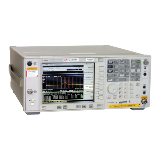
- Page 1 Installation Note Agilent PSA Series Spectrum Analyzers Audio Input, Option 107 Part Number E4440-90318 Printed in USA June 2006...
- Page 2 The information contained in this document is subject to change without notice. Agilent Technologies makes no warranty of any kind with regard to this material, including but not limited to, the implied warranties of merchantability and fitness for a particular purpose.
- Page 3 (see Note 2) Introduction This retrofit kit adds audio input capability to the PSA series spectrum analyzer. Audio input provides an additional audio signal path that is completely separate from the normal RF/IF signal chain. The Audio input has a 100K ohm input impedance, and the frequency range is 20 Hz to 250 kHz.
- Page 4 Audio Input, Option 107 NOTE 1. The installation of this kit requires that some performance testing be performed in order to assure the new option is functioning properly. This installation note includes a list of required Performance tests. Completing the performance tests does not guarantee the instrument meets all specifications.
- Page 5 2. T-10 Torx driver 3. 9/16 inch nut driver 4. X-Acto knife ❏ PSA Series Spectrum Analyzer Service Guide. This manual is available as part of the E444xAU Option OBW kits. ❏ Calibration software. Latest software information and downloads available at: http://www.agilent.com/find/calibrationsoftware...
-
Page 6: Installation Procedure
Installation Procedure Installation Procedure Preliminary Hardware Verification 1. Check for the presence of Option 233 by pressing , and look at System Show System the option list. • If Option 233 is present continue with installation of Option 107. • If Option 233 is not present then install Option 233 before continuing with the installation of Option 107. - Page 7 Installation Procedure Remove the Outer Case CAUTION If the instrument is placed on its face during any of the following procedures, be sure to use a soft surface or soft cloth to avoid damage to the front panel, keys, or input connector. 1.
- Page 8 Installation Procedure Remove the Top Brace 1. Refer to Figure 2. Use the T-10 driver to remove the top screws (3) (one screw is under the security label), and the side screws (2) attaching the top brace (1) to the deck.
- Page 9 Installation Procedure Installing the Audio Input Assembly 1. Remove the I and Q hole plugs. 2. Use an X-Acto knife to carefully pry away and remove the left side Front Panel Overlay Sticker. Ensure that you do not scratch the Front Panel. Clean off any label residue from the bezel.
- Page 10 Installation Procedure 3. Locate the Audio Input label (E4440-80100) from the kit. Remove the backing from “Audio Input” label. 4. Place the bottom of the Audio Input label so that it lines up with the bottom of the Display Bezel and so that the right edge of the label is flush with the Display Bezel. (You should be able to see a small gap between the Audio In Label and the Front Frame.) Apply the label in one motion.
- Page 11 Installation Procedure 6. Locate the Audio Input cable (8121-1432) from the kit. Install the BNC end of the Audio Input cable into the Front Panel. Ensure the BNC connector is seated properly in the D-slot and secure with Hex Nut (2950-0035). Torque to 21 in-lbs. Ensure the nut driver or wrench does not damage the overlay.
- Page 12 Installation Procedure 8. Connect the Audio Input SMB cable (8121-1432) from the Front Panel to the Audio Input board P6 as shown. Installation Note E4440-90318...
- Page 13 Installation Procedure 9. Dress the Audio Input SMB cable as shown. Installation Note E4440-90318...
- Page 14 Installation Procedure Installing the Digital IF Assembly 1. Locate the A7 Digital IF assembly in the instrument. It is in the fourth board slot from the Power Supply. 2. Remove the gray flexible coax cable W10 from the Digital IF assembly P1 and remove the Digital IF assembly.
- Page 15 Installation Procedure 4. Connect the gray flexible coax cable W10 to A7 Digital IF assembly P3 as shown. Cable designator “P3” and “GRAY (8)” are silk-screened on the PC board. Installation Note E4440-90318...
- Page 16 Installation Procedure Replace the Top Brace 1. Refer to Figure 2. 2. Carefully position the top brace on the deck. There is an alignment pin on the mid web/fan assembly that should match up with the alignment hole on the top brace. Make sure that no coaxial cables will get pinched underneath the brace.
- Page 17 Installation Procedure Install the Option Designator and License Key Number NOTE The option designator 107 and the license key number must be entered into instrument memory in addition to the correct firmware before the hardware will function. 1. Locate the Option Upgrade Entitlement Certificate in the kit and follow the directions to redeem it.
- Page 18 Installation Procedure Install New Instrument Firmware Download the PSA Update Program and the PSA Firmware Procedure from http://www.agilent.com/find/psa_firmware Follow the directions to install the firmware. Alternate method: Install the Firmware Upgrade Kit E4440AU Option UE2. Verify the Option is enabled Check for the presence of Option 107 by pressing and looking System...
- Page 19 Display Scale Fidelity Audio Distortion Audio Amplitude Accuracy End of installation For assistance, get in touch with your nearest Agilent Technologies Sales and Service Office. To find your local Agilent office access the following URL, or call the following telephone number: http://www.agilent.com/find/assist...
- Page 20 Installation Procedure Installation Note E4440-90318...