RECK MOTOmed viva2 Instruction Manual
Hide thumbs
Also See for MOTOmed viva2:
- User manual (52 pages) ,
- Instruction manual (106 pages) ,
- Short instruction (2 pages)

Related Manuals for RECK MOTOmed viva2


Summary of Contents for RECK MOTOmed viva2
- Page 1 Instruction Manual MOTOmed viva2, MOTOmed letto2 – valid for device class II – status May 2012...
- Page 2 Please use the MOTOmed only after you have read the instruction manual. If you should not understand the language of the present version, please request the instruction manual in your native language. Benutzen Sie das MOTOmed erst, nachdem Sie die Gebrauchsanweisung gelesen haben.
- Page 3 MOTOmed viva2 start/stop button Operating panel (red) foot insertion screen aid button handlebar function buttons (6 buttons) fig. 1 arm trainer operating panel (accessory) handlebar handle height adjustment arm/ big screw knobs upper body trainer / handlebar leg guides with...
- Page 4 MOTOmed gracile12 start/stop button operating panel (red) foot insertion aid screen button function buttons handlebar (6 buttons) fig. 3 operating panel arm trainer handlebar (accessory) handle big screw knobs pediatric leg guides with height adjustment calf shells arm/upper body trainer / handlebar velcro straps pediatric safety supporting module...
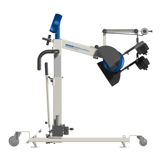
- Page 5 MOTOmed letto2 start/stop button (red) foot insertion aid operating panel button screen function buttons (6 buttons) operator remote fig. 5 stop extended pivot arm for operating leg guides panel (accessory) »TrainCare knee bending comfort« adjustment (accessory) (incl. thumb wheel) (accessory) operating handlebar panel...
- Page 6 MOTOmed letto2 leg/arm start/stop button (red) foot insertion aid operating panel button screen function buttons (6 buttons) operator remote fig. 7 stop extended pivot arm for operating leg guides panel (accessory) »TrainCare knee bending comfort« adjustment (accessory) (incl. thumb wheel) operating panel operator remote stop...
- Page 7 77 If you have furtherquestions or comments, please do not hesitate to see page 76 call your MOTOmed representative or the RECK customer service team. We are happy to assist you. Enjoy the training with your MOTOmed! INTRODUCTION...
-
Page 9: Table Of Contents
Introduction page 11 Therapy Suggestions Setup, Transport Training Prearrangements Accessories Troubleshooting Cleaning, Care, Recycling Technical Specifications, Symbols Warranty Service Safety Precautions Visual Inspection EMC Directive Index CONTENTS... - Page 11 Introduction page Application Conventional Use Liability restrictions Therapy goals Indications (diseases) Contraindications Negative side effects INTRODUCTION...
- Page 12 Not applicable are some specific power wheelchairs, standing chairs and sport wheelchairs with a large stem or with foot rests that cannot be folded or removed. Under special circumstances the MOTOmed viva2/gracile12 can also be used in supine position. MOTOmed letto2/letto2 leg/arm Training in supine position from a bed unit using the MOTOmed letto2.
- Page 13 Special bed units (treatment chairs) that are not accessible with the MOTOmed are unsuitable or require the addition of special accessories. Please use the MOTOmed letto2 leg/arm on beds that are only accessible sideways. In general MOTOmed use is only permitted in accordance to measures and safety precautions indicated in this instruction manual, with the consent of a physician / therapist, and with no contraindications found.
- Page 14 Therapy goals Prevention, reduction, and improvement of the consequences of loss or lack of movement, mainly in the following medical conditions Indications (diseases) - (spastic) paralysis or neuromuscular conditions with primary loss of function in the leg(arm)-mobility (e.g. due to stroke, multiple sclerosis, paraplegia post-polio-syndrome, Parkinson's disease, traumatic brain injury, infantile cerebral palsy, spina bifida) - restrictions of orthopedic nature such as rheumatism,...
- Page 15 (e.g. sub luxation in shoulder), acute thrombosis, decubitus and very strong osteoporosis. The therapeutic benefits versus the possible risk for a patient must be determined by the patient and by the treating doctor or therapist. Therefore, the MOTOmed therapy shall only be started after consulting the treating doctor or therapist.
-
Page 17: Therapy Suggestions
Therapy Suggestions page Overall user instructions and training suggestions How do I train appropriately? Instructions in case of cramps (spasticity) THERAPY SUGGESTIONS... - Page 18 Overall user instructions and training suggestions Before using the MOTOmed viva2 please consult your doctor and therapist in order to adjust your training program and the duration of your training sessions to your individual state of health. In order to achieve full therapy benefits, regular training with the MOTOmed is essential.
- Page 19 Do you have any questions about the MOTOmed training? Are there any difficulties with the MOTOmed ? see page 76 Please call your MOTOmed representative or the RECK Company, phone +49 7374 18-85. We are pleased to assist you. THERAPY SUGGESTIONS...
- Page 20 In case of strong cramps (spasticity) when using the MOTOmed viva2/ gracile12, the use of a wheelchair stabilizer (item no. 8 or 8K) or a chair fixation with stabilizer (item no. 511 or 524) is recommended.
- Page 21 Under special circumstances, during passive training (e.g. osteoporosis or very strong spasticity) the maximum motor power for legs and arms can be set from the start menu by pushing the buttons »setup« and then »device settings«. low motor power: e.g. osteoporosis high motor power: e.g.
-
Page 23: Setup, Transport
Setup, Transport page Setup Stand-by mode Transport Positioning of the MOTOmed letto2 / MOTOmed letto2 leg/arm SET UP, TRANSPORT... - Page 24 Setup Please contact your MOTOmed representative in cases of see page 76 transportation damage to the package or the MOTOmed device. Unpack the MOTOmed and place it on the carriage or the stand. Unpack the operating panel, in case it is not mounted on yet. Place it onto the bracket so that the connectors interlock.
- Page 25 15cm/6 in. 15cm/ fig. 11/ 12 6 in. Allen key Even those MOTOmed viva2/gracile12 devices that include a handlebar, the front stand can be pulled out as described above, in order to ensure a high safety. SET UP, TRANSPORT...
- Page 26 Stand-by mode To initiate the device, the MOTOmed needs to be externally connected to the mains by the use of the included external power supply (PMP120F-17). Please connect the mains cable of the external power supply to the power outlet, and connect the connectors of the external power supply to the MOTOmed.
- Page 27 MOTOmed viva2 / MOTOmed gracile12 To move the MOTOmed viva2/gracile12 (see page 3 and 4 fig. 2, fig. 4), hold the handlebar or the arm trainer and tilt it backwards until you can easily pull or push the MOTOmed on its large castors. In order to prevent damages during transport, the power cable is to be completely removed.
- Page 28 For longer distances on even ground you should use a trolley (or any other pushcart) in order to protect the MOTOmed viva2/gracile12. If the MOTOmed letto2 is equipped with an expandable chassis (accessory, item no.160) transport is only permitted if rails are in alignment, in order to prevent the MOTOmed letto2 from tilting over.
- Page 29 Positioning of the MOTOmed letto2 / MOTOmed letto2 leg/arm Position the MOTOmed letto2 or the MOTOmed letto2 leg/arm to the bed unit as described in section »fixing the MOTOmed to the bed«. see page 39 Subsequently, position the feet of the user into the foot shells (section »foot insertion«).
-
Page 31: Training Prearrangements
Training prearrangements page Operating panel connectors of the operating panel Operating modes MOTOmed viva2 / MOTOmed gracile12 leg trainer Preparation Foot insertion and securing aid Arm/upper body trainer Preparation MOTOmed letto2 / MOTOmed letto2 leg/arm MOTOmed letto2 preparation MOTOmed letto2 leg/arm preparation... - Page 32 Connectors of the operating panel The following connectors are available for the operating panel: see page 71 Chip card reader (accessory, not available in MOTOmed viva2 light) Connection for operator remote control (back side) (only available in letto2/letto2 leg/arm) fig. 17...
- Page 33 Further information about functions and the set up options of the two MOTOmed viva2 modes can be read in the user manual (713/W2558), or the MOTOmed viva2 light user manual (713.3/ W517). MOTOmed viva2 / MOTOmed gracile12...
- Page 34 Foot insertion and securing aid (if needed) Press the long button »insertion aid« ( ) when the MOTOmed is in stand-by mode (black screen and constant green light). By »pushing and holding« the buttons »pedals forward« or »pedals backward« you can move the foot shells (fig.
- Page 35 Please ensure a minimum insertion of 10 cm/4 in. Please make sure to be seated with a distance to the MOTOmed viva2/ gracile12 so that the arms are not stretched completely; the elbow joint should always be slightly bent.
- Page 36 MOTOmed letto2 / MOTOmed letto2 leg/arm MOTOmed letto2 Preparation Positioning procedure with the standard chassis and fixation with bed mount: Position the MOTOmed by attaching it to the foot part of the bed. Loosen the wing screw of the height adjustment and slide it up as high as possible until the bed mount...
- Page 37 Positioning of the feet into the safety foot shells: Insert the feet in the safety foot shells and fasten them with Velcro straps fig. 25 Leg guides TrainCare comfort (item no. 168): For a secure position of the lower leg and to prevent the knee from over stretching, insert the legs into the TrainCare comfort fasten those with the Velcro straps...
- Page 38 MOTOmed letto2 leg/arm Preparation Attaching the foot shells (fig. 29): In case the hand grips are attached to the MOTOmed, please remove those and attach the foot shells instead . The quick release option requires no tools for exchange. Open the red safety clip in order to loosen the fixation.
- Page 39 arm length accordingly and tighten the star knob again. Adjusting the optimal training height(fig. 32, fig. 33): At the minimum height please ensure that the foot shells do not abrade the mattress when in its lowest position. use the foot pedal to lift the the rotary arm.
-
Page 40: Accessories
Note: Do not shift or reposition the MOTOmed after completing the leg insertion. Knee bending adjustment - knee flexion adjustment: The extend of the knee flexion can be adjusted by the manual thumb wheel (fig. 34). When using the electrical knee flexion adjustment (not shown), start the MOTOmed by pushing button (fig. - Page 41 End of training End of training / analysis Push the red »start/stop« button twice to end the training . After 10 seconds the training analysis will pop up automatically. Here you can see (among other values) how long you have trained passively (with motor) and actively (with own muscle strength).
- Page 43 Accessories page Accessories MOTOmed viva 2 Safety foot shells* Leg guides with calf Self-operating foot holders Pedal radius quick adjustment Arm/upper body trainer active/passive Forearm shells with arm cuffs Hand fixation with wrist cuff Ankle joint control with fix bar scale Accessories MOTOmed gracile 12 Height adjustment of the pedal axle* Pediatric safety foot shells*...
- Page 44 (or pedal) from the pedal crank and screw it into the second hole of the pedal crank. You may request this spanner at the RECK Company if required. large pedal radius 125 mm/4.9 in.
- Page 45 Make sure that the minimum insertion of 3 cm/1.2 in. is maintained. As soon as you have positioned the feet into the foot shells, wrap the Velcro straps around the calves. see page 33 Make sure the Velcro straps are securely wrapped around the calves (fig.
- Page 46 Adjusting the spring pressure of the foam roll The pressure of the foam roll can be adjusted by tightening (counter- clockwise) or loosening (clockwise) the set screw at the bottom of the foot holder. hexagon fig. 40/ 41 L = 0 mm - large pressure L = 10 mm - small pressure The position of the set screw must not exceed 10 mm / 0.4 in.! Pedal radius quick adjustment...
- Page 47 4b. Stageless/continuous adjustment: Using the Allen screw, the foot shells can be set at any position on the pedal crank. 5. Adjust the other foot shell accordingly. 6. Please make sure the pedal radius of both sides is matching! 7. Plug in the MOTOmed. Allen screw snap knob Allen screw...
- Page 48 Forearm shells with arm cuffs item no. 556 cross grip forearm shell pedal crank fig. 44 wing screw The forearm shells can only be used in combination with the arm/ upper body trainer (item no. 250 and 218). In order to allow some lateral mobility for the forearms, the shells have a pivot for horizontal movement.
- Page 49 Hand fixation with wrist cuffs item no. 562 The hand fixation with wrist cuff enables quick and simple attachment to the arm/upper body trainer of weak or paralyzed handsto the arm/ upper body trainer, the handlebar, or any hand fixation for that matter. fig.
- Page 50 Accessories MOTOmed gracile12 Height adjustment of the pedal axle ranging from 26 to 46 cm/10.4 to 18.4 in. (from the ground floor) The MOTOmed gracile12 is the first and unique movement therapy device for children with adjustable pedal axle and foot shell height. Thus, adjustment to the needs of children is perfectly optimized.
- Page 51 Pediatric Safety Foot item no. 585 The pediatric foot shells (inside measurement: width: 10.5 cm/4.1 in., length: 21.7 cm/8.5 in.) are softly padded and have a large side panel for foot and ankle protection. fig. 49 The pediatric safety foot shells provide a secure hold of the feet. This is particularly important for people with (complete) paralysis and for people with spasticity.
- Page 52 Pediatric leg guides with calf shells item no. 545 calf shells Velcro leg guides wing screw fig. 50/ 51 You can find a detailed description of the leg guides on page 44, see item no. 502. 2-stage pedal radius adjustment The pedal radius can be decreased (3.5 cm/1.4 in.) and increased (7 cm/2.8 in.) with an Allen key within seconds.
- Page 53 3. Insufficiently tightened Allen screws of the ball bearing ring are not subject to warranty coverage by RECK-Technik GmbH & Co. KG. ACCESSORIES...
- Page 54 foot shell bearing Allen screw ball bearing tension fig. 54 ring in the pedal crank If you wish to change the pedal radius frequently, we recommend the special accessory 3-level pedal radius quick adjustment (item no. 588. Self-operating foot holder item no.
- Page 55 Arm/upper body trainer active/passive item no. 599 You can find a detailed description of the arm/upper body trainer in chapter 4 on page 34. fig. 57 Pediatric forearm shell with arm cuffs item no. 556K You can find a detailed description of the pediatric forearm shells on page 48, see item no.
- Page 56 MOTOmed letto2 Accessories »TrainCare comfort« leg guides with calf shells item no. 168 The »TrainCare comfort« leg guides (fig. 59) support the lower legs and prevent them from unintentional moving to the side, as they also prevent the knee joints from overstretching and blocking. For paralyzed or comatose patients it is absolutely vital to use the »TrainCare comfort«...
- Page 57 replace if needed on a regular basis. The manufacturer and its distributors do not assume liability for damages caused by negligence of maintenance. The calf shell rotary adjustment (fig. 59) is individually settable on the right or the left side. The rotary adjustment can be set to offer best possible hold to the patient's legs while training with the MOTOmed letto2.
- Page 58 Position the MOTOmed letto2 to the bed unit as close and centered as possible and push the red side of the foot pedal (fig. 60) to fix the MOTOmed in place. To release the ground fixation push the green side of the foot pedal.
- Page 59 Knee bending adjustment (manual) item no. 162 The distance between the rotary arm and the user can be adjusted by thumb wheel. That allows for adjustment of the knee bending during the training. fig. 62 Rotating to the right side leads to more bending while rotation to the left side leads to more flexion.
- Page 60 Loosen the fixing screws . Position the operating panel into the right position and tighten the fixing screws again. Loosening the fixing screws allows for tilting up the operating panel. If the pivot arm is too short, loosen the fixing screws and pull-out the pivot arm to extend it for up to an additional 30 cm/11in.
- Page 61 Forearm shells with arm cuffs item no. 556 fig. 65 You can find a detailed description of the forearm shells with arm cuffs on page 48, see item no. 556. Hand fixation with wrist cuffs item no. 562 fig. 66 You can find a detailed description of the hand fixation with wrist cuffs on page 49, see item no.
-
Page 62: General Information
General information Only the use of original parts of the RECK Company is permitted. Additional accessories are shown in the current product overview. Individual product adjustments are available upon request. Please contact your MOTOmed representative or the RECK Company contacts see page 76 in chapter service. -
Page 63: Troubleshooting
Troubleshooting page Safety instructions for Troubleshooting The MOTOmed has an uneven and bumpy run or is making noises The MOTOmed does not work at all or operating panel does not react The MOTOmed stops during a training session and generates an error message Simple error Electronic error Overview of most important error messages... - Page 64 MOTOmed. For security reasons, please pull the mains cable from the outlet before starting the maintenance. In cases of unlisted malfunctions, or if you have any questions, please refer to the RECK customer service department or to an authorized see page 76 MOTOmed representative.
- Page 65 If the error reoccurs, please contact your MOTOmed representative or the technical support department at the RECK Company. Electronic error Any electronic error requires disconnection of the power supply (unplug the MOTOmed).
- Page 66 If the error occurs repeatedly, please contact the technical support at the RECK Company or an authorized local partner. see page 76 Overview of the most important error messages The most important error codes are listed below.
-
Page 67: Cleaning, Care, Recycling
Cleaning, Care, Recycling Before cleaning the MOTOmed, the device must be unplugged from the mains (electric outlet) so that the power supply is completely disconnected. Clean the surface of your MOTOmed with a soft, moist cloth. It is absolutely crucial that no water enters the device. If several persons use the MOTOmed, parts that may get in touch with sensible body areas (e.g. -
Page 69: Technical Specifications, Symbols
Technical Specifications, Symbols Dimensions and Weight viva2 gracile12 letto2 (basic model) 94 cm/37 in. 76 - 100 cm/ 124 - 156 cm/ 60 cm/23.6 in. 29 - 39 in. 48.8 - 61.4 in. height 56 cm/22 in. 45 cm/17.7 in. 68 cm/27 in. - Page 70 Classification Protection class II, Type BF According to MPG ll a According to MDR (SOR/98-282) NBOG Code 1108 active rehabilitation devices FDA product code BXB - exerciser powered Maximum user weight 135 kg/300lb (with the gracile12: 90 kg/ 200 lbs) * battery only available if the optional chip card reader is installed.
- Page 71 Do not step inside the MOTOmed and do not train in a standing position. Do not allow any liquids on the MOTOmed: Use the device only in a dry state. The MOTOmed viva2/gracile12/letto2 was tested by the UL test institution according to current medical standard 60601-1. TECHNICAL SPECIFICATIONS, SYMBOLS...
- Page 72 Symbol description - connectors of the operating see page 32 panel insert identification card serial interface remote control heart rate Maximum user weight for the gracile12: 90 kg/ 198 lbs...
-
Page 73: Warranty
1. The claim is not about wearing parts (e.g. Velcro straps). 2. Previous maintenance (servicing, inspection, repair) was conducted only by a RECK service agent or the RECK Company in a proper manner. 3. No modifications have been made on the MOTOmed. - Page 74 III. Other By request of the RECK Company, defective components replaced due to manufacturer or material defects are to be returned to the RECK Company after the repair. Replaced parts become property of RECK-Technik GmbH & Co. KG. In case of part delivery on warranty, an extension of warranty period does not come into effect.
-
Page 75: Service
Service Should you have any questions we will be happy to assist you. Please call us - your questions and suggestions are always welcome. We will gladly return your call. Please have the serial number (SN) of your MOTOmed right at hand. You can find it on the label on the large front tube of your MOTOmed. - Page 76 +49 7374 18-480 email: service@motomed.com The RECK Company places high value on constant optimization of its products. That is why we want to hear about your experiences with the MOTOmed. We would appreciate your feedback. Please contact us at the telephone numbers above, or by writing an e-mail or fax, either to us directly, or your local MOTOmed representative.
-
Page 77: Safety Precautions
Safety Precautions Overall suggestions The first time use of the MOTOmed must always be supervised by a qualified person giving instructions. Assessment of MOTOmed training in regard to your health situation as well as the time, duration, and intensity of the training periods has to be discussed with your doctor or physiotherapist before you start the training. - Page 78 (push button ), when you are in the start screen. In the MOTOmed viva2 light, these settings are found in the training menu. In the menu »display and volume« at start screen information you can set the adjusted motor power to be displayed in the start screen (not available in the MOTOmed viva2 light).
- Page 79 Users with body weight of 135-250 kg / 297-551 lbs (in gracile12: 90-150 kg / 198-330 lbs) please use stronger foot shells in order to prevent damage to the MOTOmed. Only put your feet into the foot shells while seated (or laying down). Never step in while standing upright and by full force / weight.
- Page 80 While height adjusting the arm trainer, pay attention to sufficient legroom. When using the leg trainer, the legs must not collide with the arm trainer. MOTOmed letto2 If the MOTOmed letto2 is equipped with an expandable chassis see page 58 (accessory, item no.
- Page 81 If the user's knee joints are stretching too much during the pedal movement, the distance between the user and the MOTOmed letto2 needs to be reduced. For paralyzed or comatose patients, the inclusion of the accessory »TrainCare leg guides comfort« (item no. 168) is required. These see page 56 leg guides prevent the overstretching of the knee joints, or shifting sideways of the legs.
- Page 82 If the red »start/stop« button fails to stop the MOTOmed, immediately adjust the speed to 1 rpm and finish your training right away, or unplug the mains from the outlet. You can train again as soon as the malfunction is been eliminated. In case of changes to the pedal length, please note that the rate of force on the cranks may change.
- Page 83 In order to avoid fire hazard or electrical shock the MOTOmed must never be operated if the casing has been removed. The MOTOmed must never be operated in a wet or humid environment. The MOTOmed must never be operated by any unqualified person and metal objects must never be inserted.
- Page 84 Repairs may be affected only by or under direction and supervision of individuals (qualified personnel) whose qualified training, knowledge and experience enable them to evaluate the repair and to recognize the potential effects and hazards that might result out of the repair. The MOTOmed must only be opened by qualified and trained persons.
-
Page 85: Visual Inspection
Visual Inspection Guidance for visual inspection of MOTOmed before the start of training Your MOTOmed is a high-quality medical device and thus has been developed by by specific high safety and quality standards, in accordance to guidelines governing the production of medical devices. - Page 86 The use of a damaged mains cable tested and authorized part of is therefore strictly prohibited. the RECK Company. Therefore, please contact your RECK service partner. Is the feeder positioned Never use a mains cable...
- Page 87 Test step Necessary measures in case Explanation of fault detection during visual inspection Is the external mains Position the mains supply so Disconnecting and removing the supply disconnected from that it does not touch the mains supply of the device counts MOTOmed.
- Page 88 Test step Necessary measures in case Explanation of fault detection during visual inspection If the device is equipped Pull out the small foot stand Pulling out the small front stand with an arm/upper sufficiently. Pay attention to prevents tilting of the device. keep a minimal insertion of body trainer, or if the handlebar is heavily used:...
- Page 89 Test step Necessary measures in case Explanation of fault detection during visual inspection If training from a Pull the brakes and check if The wheelchair must not move wheelchair: Are the wheelchair is in a steady out of position during training. position.
- Page 90 Test step Necessary measures in case Explanation of fault detection during visual inspection Are the pedal cranks Please remove all objects from Please pay attention that nothing moving freely? Has the the crank area, particularly gets caught into the motor-driven those that may get tangled in rotating components.
-
Page 91: Emc Directive
EMC Directive page Manufacturer's Declaration - electromagnetic emissions Manufacturer's Declaration - electromagnetic immunity Recommended distance EMC-INFORMATION... - Page 92 Electromagnetic environment - guidance HF emissions Group 1 The MOTOmed viva2 uses RF energy only according to CISRP 11 for its internal function. Therefore, its RF emissions are very low and are not likely to cause any interference in nearby electronic equipment.
- Page 93 Manufacturer's Declaration - electromagnetic immunity The MOTOmed is supposed to be operated in the electromagnetic environment described below. The customer or user of the MOTOmed has to guarantee the use in the appropriate environment. Immunity IEC 60601 - test level Electromagnetic environment - test guidance...
- Page 94 Portable and mobile RF communications equipment should be used not closer to any part of the MOTOmed viva2 including cables, than the recommended separation distance calculated from the equation appropriate for the frequency of the transmitter: Recommended separation distance: Conducted RF d = 3.5/3 P = 1.17 P...
- Page 95 Recommended separation distances between portable and mobile RF communications equipment and the MOTOmed The MOTOmed is supposed to be operated in an electromagnetic environment where the RF interference is controlled. The customer or user of the MOTOmed can help avoid electromagnetic interference by keeping the separation distances between portable and mobile RF communications equipment (transmitters) and the MOTOmed - which depends on the performance of the communication device as...
-
Page 97: Index
Index accessories display measurements analysis ankle joint adjustment: application electromagnetic emissions arm shells electromagnetic immunity arm/upper body trainer electronic errors active/passive end of training error messages expandable chassis bed mount expert mode extended pivot arm for operating panel calf shells care CE sign first time use... - Page 98 Index hand fixation maintenance handlebar marking height adjustment measurements hints MovementProtector immunity negative side effects indication indications insert/secure legs operating mode introduction operating panel operator remote stop knee flexion adjustment pedal radius quick adjustment positioning- MOTOmed letto2 leg guide power consumption power requirements recommended separation distances...
- Page 99 Index safety unpack safety foot shells safety precautions self-operating foot holders visual Inspection separation distances serial number service setup warranty signs and symbols weight description weight restrictions SpasmControl spasticity (cramps) standard mode year of construction stand-by mode stand-by-mode supporting module surrounding conditions technical specifications, symbols...
- Page 100 GB 713/W2559b (entspricht dt. Version "b") 06.12 binSt We reserve the right to technical changes according to the progress. Reprint, also extracts requires a written permission of the RECK Company.
- Page 102 Instruction Manual MOTOmed viva2, MOTOmed letto2 move differently Technik GmbH & Co. KG, www.motomed.com Reckstr. 1–5, 88422 Betzenweiler, GERMANY ph: +49 7374 18-85, fax +49 7374 18-480, info@motomed.com...
Need help?
Do you have a question about the MOTOmed viva2 and is the answer not in the manual?
Questions and answers