
Related Manuals for Kontron AM4100


Summary of Contents for Kontron AM4100
- Page 1 » User Guide « AM4100 Single Mid- and Full-Size AMC Module based on the Freescale™ MPC8641D Dual-Core PowerPC® Processor Doc. ID: 36126, Rev. 2.0 May 11, 2011 If it’s embedded, it’s Kontron.
-
Page 2: Imprint
Disclaimer Copyright © 2011 Kontron AG. All rights reserved. All data is for information purposes only and not guaranteed for legal purposes. Information has been carefully checked and is believed to be accurate; however, no responsibility is assumed for inaccuracies. Kontron and the Kontron logo and all other trademarks or registered trademarks are the property of their respective own- ers and are recognized. -
Page 3: Table Of Contents
1.4.3 Board Layouts ................. 1 - 8 1.5 Technical Specification ................1 - 9 1.6 Kontron Software Support ..............1 - 11 1.7 Standards ....................1 - 12 1.8 Related Publications ................1 - 13 Functional Description ............2 - 3 2.1 Processor and Memory ................ - Page 4 2.5 Module Management ................2 - 21 2.5.1 Module Management Controller ............2 - 21 2.5.1.1 MMC Signals Implemented on the AM4100 ......2 - 22 Installation ................3 - 3 3.1 Safety Requirements ................3 - 3 3.2 AM4100 Initial Installation Procedures ............3 - 4 3.3 Standard Removal Procedures ..............3 - 4...
- Page 5 AM4100 Preface Configuration ................4 - 3 4.1 Configuration of DIP Switches ..............4 - 3 4.1.1 SW2 DIP Switch Configuration ............4 - 3 4.1.1.1 POST Code or User-Specific LED Configuration ....4 - 4 4.1.1.2 NetBootLoader Firmware Flash Configuration ....... 4 - 4 4.1.1.3...
- Page 6 Preface AM4100 NetBootLoader ................. 5 - 3 5.1 General Operation ...................5 - 3 5.2 NetBootLoader Interfaces ................5 - 3 5.2.1 SER0 Serial Interface ..............5 - 4 5.2.2 SER1 Serial Interface ..............5 - 4 5.2.3 Ethernet Port Interfaces ..............5 - 4 5.3 NetBootLoader Functions ................5 - 4...
- Page 7 6.2.3 Module Management Power Consumption ........6 - 4 6.3 Payload Power Consumption of the AM4100 ......... 6 - 4 6.4 IPMI FRU Payload Power Consumption ..........6 - 5 6.5 Payload Start-Up Current of the AM4100 ..........6 - 5 Thermal Considerations ............
- Page 8 Preface AM4100 This page has been intentionally left blank. Page viii ID 36126, Rev. 2.0...
-
Page 9: List Of Tables
AM4100 Preface List of Tables System Relevant Information ..............1 - 5 AM4100 Main Specifications ..............1 - 9 Standards ....................1 - 12 Related Publications ................1 - 13 Module Management LED Function ............2 - 7 User-Specific LED Function ..............2 - 8 POST Code Example ................ - Page 10 Motorola S-Records Commands .............. 5 - 8 DC Operational Input Voltage Ranges ............. 6 - 3 Power Cons.: AM4100 MPC8641D, 1.0 GHz, 400 MHz Platform Freq..6 - 5 Power Cons.: AM4100 MPC8641D, 1.32 GHz, 528 MHz Platform Freq... 6 - 5 Power Cons.: AM4100 MPC8641D, 1.5 GHz, 600 MHz Platform Freq..
- Page 11 Processor Temperature Sensor Placement (AM4100 Top View) .... 7 - 3 Board Temperature Sensor Placement (AM4100 Bottom View) ....7 - 3 Operational Limits for the Mid-Size AM4100 with 1.0 GHz ...... 7 - 6 Operational Limits for the Mid-Size AM4100 with 1.32 GHz ....7 - 7 Operational Limits for the Full-Size AM4100 with 1.5 GHz ......
- Page 12 Preface AM4100 This page has been intentionally left blank. Page xii ID 36126, Rev. 2.0...
-
Page 13: Proprietary Note
Preface Proprietary Note This document contains information proprietary to Kontron. It may not be copied or transmit- ted by any means, disclosed to others, or stored in any retrieval system or media without the prior written consent of Kontron or one of its authorized agents. -
Page 14: Explanation Of Symbols
Preface AM4100 Explanation of Symbols Caution, Electric Shock! This symbol and title warn of hazards due to electrical shocks (> 60V) when touching products or parts of them. Failure to observe the pre- cautions indicated and/or prescribed by the law may endanger your life/health and/or result in damage to your material. -
Page 15: For Your Safety
However, the life expectancy of your product can be drastically reduced by improper treatment during unpacking and installation. Therefore, in the interest of your own safety and of the correct operation of your new Kontron product, you are requested to conform with the following guidelines. -
Page 16: General Instructions On Usage
General Instructions on Usage In order to maintain Kontron’s product warranty, this product must not be altered or modified in any way. Changes or modifications to the device, which are not explicitly approved by Kontron and described in this manual or received from Kontron’s Technical Support as a special han- dling instruction, will void your warranty. -
Page 17: Two Year Warranty
As a result, the products are sold “as is,” and the responsibility to ensure their suit- ability for any given task remains that of the purchaser. In no event will Kontron be liable for direct, indirect or consequential damages resulting from the use of our hardware or software products, or documentation, even if Kontron were advised of the possibility of such claims prior to the purchase of the product or during any period since the date of its purchase. - Page 18 Preface AM4100 This page has been intentionally left blank. Page xviii ID 36126, Rev. 2.0...
-
Page 19: Introduction
AM4100 Introduction Chapter Introduction ID 36126, Rev. 2.0 Page 1 - 1... - Page 20 Introduction AM4100 This page has been intentionally left blank. Page 1 - 2 ID 36126, Rev. 2.0...
-
Page 21: Board Overview
The board is capable of supporting core frequencies ranging from 1.0 GHz to 1.5 GHz providing up to 600 MHz platform speed. The processor and the memory are soldered on the AM4100 which results in higher Mean Time Between Failures (MTBF) and a significant improvement in cooling. -
Page 22: Board-Specific Information
AM4100 Board-Specific Information Due to the outstanding features of the AM4100, such as superior processing power and flexible interconnect topologies, this AMC board provides a highly scalable solution not only for a wide range of telecom and data network applications, but also for several highly integrated industrial environment applications with solid mechanical interfacing. -
Page 23: System Relevant Information
Table 1-1: System Relevant Information SUBJECT INFORMATION Hardware Requirements The AM4100 can be installed on any AMC-supporting carrier board or MicroTCA backplane with the following AMC Card-edge connector port mapping: Common Options Region ports 0-1 • Two Gigabit Ethernet SerDes ports •... -
Page 24: Am4100 Functional Block Diagram
Introduction AM4100 Figure 1-1: AM4100 Functional Block Diagram Page 1 - 6 ID 36126, Rev. 2.0... -
Page 25: Front Panel
• ULED0 (red/green/amber): Freely configurable or POST code LED Connectors • Serial Connector • Gigabit Ethernet Connector For further information on the LEDs used on the AM4100, refer to section 2.3.1, “Front Panel LEDs”. ID 36126, Rev. 2.0 Page 1 - 7... -
Page 26: Board Layouts
Introduction AM4100 1.4.3 Board Layouts Figure 1-3: AM4100 Board Layout (Top View) DDR2 Memory Flash Flash (GbE A) MPC8641D (SoC) (GbE B) Hot Swap Microswitch Figure 1-4: AM4100 Board Layout (Bottom View) DIP Switch DDR2 Memory NAND Flash R452 R453... -
Page 27: Technical Specification
Freescale MPC8641D processor, 1.5 GHz, 600 MHz platform frequency • All microprocessors are provided in a 1023 FC-CBGA packaging. Please contact Kontron for further information concerning the suitability of other Freescale processors for use with the AM4100. Memory Main Memory: Up to 2 GB unbuffered DDR2 SDRAM memory with ECC running at 600 MHz •... - Page 28 The MMC is accessible via a local IPMB (IPMB-L) and Keyboard Con- • troller Style (KCS) Interfaces. Hot Swap The AM4100 has full hot swap capability. Thermal Management CPU and board overtemperature protection is provided by: Four temperature sensors for monitoring the board temperature •...
-
Page 29: Kontron Software Support
Due to its close relationship with the software manufacturers, Kontron is able to produce and support BSPs and drivers for the latest operating system revisions thereby taking advantage of the changes in technology. -
Page 30: Standards
Introduction AM4100 Standards The Kontron AMC boards comply with the requirements of the following standards. Table 1-3: Standards COMPLIANCE TYPE STANDARD TEST LEVEL Emission EN55022 EN61000-6-3 EN300386 Immission EN55024 EN61000-6-2 EN300386 Electrical Safety EN60950-1 Mechanical Mechanical Dimensions IEEE 1101.10 Environmental and... -
Page 31: Related Publications
Customers desiring to perform further environmental testing of Kontron prod- ucts must contact Kontron for assistance prior to performing any such testing. This is necessary, as it is possible that environmental testing can be destructive when not performed in accordance with the applicable specifications. - Page 32 Introduction AM4100 This page has been intentionally left blank. Page 1 - 14 ID 36126, Rev. 2.0...
-
Page 33: Functional Description
AM4100 Functional Description Chapter Functional Description ID 36126, Rev. 2.0 Page 2 - 1... - Page 34 Functional Description AM4100 This page has been intentionally left blank. Page 2 - 2 ID 36126, Rev. 2.0...
-
Page 35: Processor And Memory
Processor and Memory 2.1.1 Processor The AM4100 supports the latest Freescale dual-core MPC8641D processor family up to speeds of 1.5 GHz with up to 600 MHz platform speed, such as: • Freescale MPC8641D processor, 1.0 GHz, 400 MHz platform frequency •... -
Page 36: Memory
Additionally, it provides a very tight frequency tolerance at low power consumption. The AM4100 does not include a 3 V lithium battery or a GoldCap power source for RTC backup. The RTC can be powered from the management power. However, if this power is switched off, the RTC will lose its data. -
Page 37: Watchdog Timer
2.2.4.2 NAND Flash Disk Controller The AM4100 supports up to 4 GB of NAND Flash memory in combination with the SST55LD019 NAND Flash Disk Controller, which is connected to the MPC8641D’s local bus controller (LBC). -
Page 38: Board Interfaces
AM4100 Board Interfaces 2.3.1 Front Panel LEDs The AM4100 is equipped with three Module Management LEDs and four User-Specific LEDs. The User-Specific LEDs can be configured via two onboard registers (see section 4.6.14, “User- Specific LED Configuration Register”). Figure 2-1:... -
Page 39: Module Management Led Function
AM4100 Functional Description Table 2-1: Module Management LED Function OVERRIDE MODE MODULE state selectable by user MANAGEMENT COLOR NORMAL MODE or carrier, depending on PICMG LED command LED1 Off = module powered / running Depends on carrier or user On = module out of service... -
Page 40: User-Specific Led Function
Functional Description AM4100 Table 2-2: User-Specific LED Function FUNCTION DURING USER- FUNCTION DEFAULT FUNCTION BOARD INITIALIZATION SPECIFIC COLOR DURING POWER-ON AFTER POWER-ON (IF POST CODE CONFIGURATION IS ENABLED) ULED3 When lit up during processor overtemperature power-on, it indicates a above 105 °C power failure. -
Page 41: Post Code Example
Once activated, the overtemperature event remains latched until a cold restart of the AM4100 is undertaken (all power off and then on again). -
Page 42: Dip Switches
2.3.2 DIP Switches The AM4100 is equipped with two DIP switches, one 4-bit general purpose DIP switch, SW2, and one 2-bit IPMI configuration DIP switch, SW3, both situated on the reverse side of the board. For further information, refer to chapter 4.1, Configuration of DIP Switches. -
Page 43: Serial Ports
Functional Description 2.3.4 Serial Ports The AM4100 provides two serial ports, SER0 and SER1, both fully compatible with the 16550 UART. The SER0 interface provides receive and transmit signals as well as additional signals for handshaking mode. SER0 is available on the front panel as a serial RS232, 8-pin, RJ45, con- nector J4. -
Page 44: Gigabit Ethernet Connectors
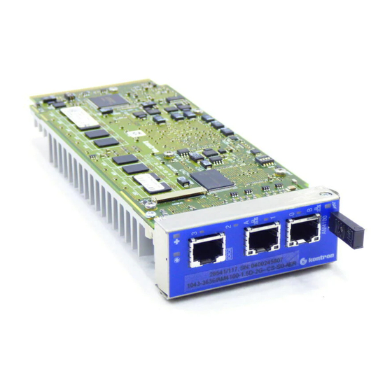
Functional Description AM4100 2.3.5.1 Gigabit Ethernet Connectors Figure 2-3: Gigabit Ethernet Connectors J2/J3 The Ethernet connectors, J2 and J3 are realized as RJ45 connectors. The interfaces provides automatic detection and switching between 10Base-T, 100Base- TX and 1000Base-T data transmission (Auto-Negotia- tion). -
Page 45: Amc Interconnection
Functional Description AMC Interconnection The AM4100 communicates with the carrier board or the MicroTCA backplane via the AMC Card-edge connector, which is a serial interface optimized for high-speed interconnects. The AMC Card-edge connector supports a variety of fabric topologies divided into five functional groups: •... -
Page 46: Am4100 Port Mapping
Functional Description AM4100 Figure 2-4: AM4100 Port Mapping AM4100 AM4100 Port No. Standard w/ x4 PCIe w/ x4 SIO Port Mapping Port Mapping Port Mapping TCLKA System Tick (optional) System Tick (optional) Clocks TCLKB not used not used FCLKA PCI Express Reference Clock... - Page 47 These two supply voltages must have power-good indicators so that the system management can detect boot sequence events and nominal operating conditions. The AM4100 operates with payload power in the range of 10.8 V to 13.2 V, and with manage- ment power of 3.3 V ± 5%.
-
Page 48: Pinout Of Amc Card-Edge Connector J1
The AMC Card-edge connector is a high-speed serial interface and supports 170 pins. The fol- lowing table provides pinout information for AMC Card-edge connector J1. The shaded table cells indicate signals that are not used on the AM4100. Table 2-7:... - Page 49 AM4100 Functional Description Table 2-7: Pinout of AMC Edge Connector J1 (Continued) BASIC SIDE (COMPONENT SIDE 1) EXTENDED SIDE (COMPONENT SIDE 2) DRIVEN DRIVEN SIGNAL FUNCTION SIGNAL FUNCTION Tx2+ Not Connected Rx17+ Not Connected Carrier Tx2- Not Connected Rx17- Not Connected...
- Page 50 Functional Description AM4100 Table 2-7: Pinout of AMC Edge Connector J1 (Continued) BASIC SIDE (COMPONENT SIDE 1) EXTENDED SIDE (COMPONENT SIDE 2) DRIVEN DRIVEN SIGNAL FUNCTION SIGNAL FUNCTION Rx5+ PCIe-1 Receiver + / Carrier Rx13+ Not Connected Carrier Serial RapidIO 1...
- Page 51 AM4100 Functional Description Table 2-7: Pinout of AMC Edge Connector J1 (Continued) BASIC SIDE (COMPONENT SIDE 1) EXTENDED SIDE (COMPONENT SIDE 2) DRIVEN DRIVEN SIGNAL FUNCTION SIGNAL FUNCTION SDA_L IPMB-L Data IPMI Rx10+ Not Connected Carrier Agent Payload Power Carrier...
-
Page 52: Reserved Pins Description
JTAG Test Clock Input 3.3V TTL level Note ... The JTAG pins are connected to the onboard FPGA logic and can be used to update the onboard logic. For further information, contact Kontron’s Technical Support. Page 2 - 20 ID 36126, Rev. 2.0... -
Page 53: Module Management
The address offset of the LPC KCS interface is 0xCA2, 0xCA3 and 0xCA0, 0xCA4. Fur- thermore, the MMC is able to communicate directly with the FPGA via the I²C interface. The I²C interface can be used to read the POST codes and configure the AM4100’s default boot parameters. -
Page 54: Mmc Signals Implemented On The Am4100
Functional Description AM4100 2.5.1.1 MMC Signals Implemented on the AM4100 The MMC implements several signals to monitor and control the different board functions. These signals are indicated in the following tables. Table 2-11: Processor Supervision SIGNAL DESCRIPTION MMC FUNCTION PCI reset... -
Page 55: Temperature Signals
AM4100 Functional Description Table 2-14: Temperature Signals SIGNAL DESCRIPTION MMC FUNCTION Processor temperature Processor die temperature Monitor temperature Inlet AMC sensor temperature Inlet board temperature sensor near the Monitor temperature AMC Card-edge connector Outlet AMC sensor temperature Outlet board temperature sensor near the... - Page 56 Functional Description AM4100 This page has been intentionally left blank. Page 2 - 24 ID 36126, Rev. 2.0...
-
Page 57: Installation
AM4100 Installation Chapter Installation ID 36126, Rev. 2.0 Page 3 - 1... - Page 58 Installation AM4100 This page has been intentionally left blank. Page 3 - 2 ID 36126, Rev. 2.0...
-
Page 59: Safety Requirements
Installation Installation The AM4100 has been designed for easy installation. However, the following standard precau- tions, installation procedures, and general information must be observed to ensure proper in- stallation and preclude damage to the board, other system components, or injury to personnel. -
Page 60: Am4100 Initial Installation Procedures
3. Using minimal force, push the extractor/locking handle towards the board until fully re- tracted. 4. Connect all external interfacing cables to the board as required. 4. The AM4100 is now ready for operation. For operation of the AM4100, refer to the appro- priate AM4100-specific software, application, and system documentation. Standard Removal Procedures To remove the board proceed as follows: 1. -
Page 61: Am4100 Hot Swap Procedures
• When the carrier IPMI controller receives the handle opened event, the carrier sends a command to the MMC with a request to perform short blinking of the BLUE HS LED. This indicates to the operator that the AM4100 is waiting to be deactivated. -
Page 62: Hot Swap Insertion Procedures
5. Dispose of the board as required. 3.4.2 Hot Swap Insertion Procedures The following procedures are applicable when inserting the AM4100 in a running system. 1. Ensure that the safety requirements indicated section 3.1 are observed. Warning! Failure to comply with the instruction above may cause damage to the board or result in improper system operation. -
Page 63: Software Installation
The carrier enables the payload power for the AM4100, and the Module Manage- ment LEDs and the User-Specific LEDs emit a short blink. 4. The AM4100 is now ready for operation. For operation of the AM4100, refer to appropri- ate AM4100-specific software, application, and system documentation. - Page 64 Installation AM4100 This page has been intentionally left blank. Page 3 - 8 ID 36126, Rev. 2.0...
-
Page 65: Configuration
AM4100 Configuration Chapter Configuration ID 36126, Rev. 2.0 Page 4 - 1... - Page 66 Configuration AM4100 This page has been intentionally left blank. Page 4 - 2 ID 36126, Rev. 2.0...
-
Page 67: Configuration Of Dip Switches
AM4100 Configuration Configuration Configuration of DIP Switches 4.1.1 SW2 DIP Switch Configuration The General Purpose DIP switch, SW2, consists of four switches for board configuration: switch 1 for POST code or User-Specific LED configuration, switch 2 for NetBootLoader (NBL) Firmware Flash configuration, and switch 4 for configuring the low-memory address offset mode of the e600 core 1. -
Page 68: Post Code Or User-Specific Led Configuration
For the NetBootLoader (NBL) Firmware there are two redundant NOR Flash chips on the AM4100 board. One chip is intended to provide a backup in the event that the other gets cor- rupted. If the currently used NetBootLoader Flash is corrupted due to physical damage or a faulty Flash upgrade, either the Module Management Controller or the SW2 DIP switch can se- lect the redundant Flash, and the system can boot from it. -
Page 69: Sw3 Dip Switch Configuration
Selects run mode: FRU data set 0, sub-device 2 (sRIO Host) Selects run mode: FRU data set 0, sub-device 3 (sRIO Agent) For further information, refer to the IPMI FW User Guide for the AM4100 Module provided with the documentation CD. -
Page 70: Jtag Chain Configuration
Reserved Local Chip Select Line Usage The MPC8641D processor provides eight local chip select (LCS) lines representing eight memory mapped areas. On the AM4100 the local chip select lines will be used according to the following table: Table 4-7: Chip Select Line Usage... -
Page 71: Memory Map
AM4100 Configuration Memory Map The AM4100 board uses the following memory map. Table 4-8: I/O Address Map START ADDRESS END ADDRESS SIZE WIDTH DESCRIPTION 0x0_FFF0_8000 0x0_FFFF_FFFF Not used 0x0_FFF0_0000 0x0_FFF0_7FFF 32kB LCS5 8bit Core 1 Startup Word 0x0_FE00_0000 0x0_FFEF_FFFF Not used... -
Page 72: Host Cpu Register Map
Configuration AM4100 4.5.1 Host CPU Register Map The following table sets out the host CPU registers. The blue shaded table cells indicate MMC- specific registers. Table 4-9: Host CPU Register Map ADDRESS DEVICE 0xEC00_0002 Memory Configuration Register 0xEC00_0008 Interface Configuration Register... -
Page 73: Host Cpu Registers
Configuration Host CPU Registers The following registers are special registers which the AM4100 uses to watch and/or configure the onboard hardware special features and the AMC control signals. Normally, only the system Firmware uses these registers, but they are documented here for application use as required. -
Page 74: Interface Configuration Register
Configuration AM4100 4.6.2 Interface Configuration Register The Interface Configuration Register holds a series of bits defining the Ethernet, PCI Express (PCIe) and Serial RapidIO (sRIO) configurations. Table 4-11: Interface Configuration Register REGISTER NAME INTERFACE CONFIGURATION REGISTER ADDRESS 0xEC00_0008 RESET NAME... -
Page 75: Post Code Register
AM4100 Configuration 4.6.3 POST Code Register The values stored in this register are displayed by the User-Specific LEDs when the switch 1 of SW2 DIP switch is set to OFF. Table 4-12: POST Code Register REGISTER NAME POST CODE REGISTER... -
Page 76: Mmc I/O Status Register
Configuration AM4100 4.6.5 MMC I/O Status Register The MMC I/O Status Register describes the MMC control signals. The register is read only and can be configured only by the Module Management Controller. Table 4-14: MMC I/O Status Register REGISTER NAME... -
Page 77: Watchdog Timer Control Register
4.6.6 Watchdog Timer Control Register The AM4100 has one Watchdog Timer provided with a programmable timeout ranging from 125 ms to 256 s. Failure to strobe the Watchdog Timer within a set time period results in a system reset or an interrupt. - Page 78 Configuration AM4100 Table 4-15: Watchdog Timer Control Register REGISTER NAME WATCHDOG TIMER CONTROL REGISTER ADDRESS 0xEC00_0282 RESET NAME DESCRIPTION ACCESS VALUE Watchdog timer expired status bit: 0 = Watchdog Timer has not expired 1 = Watchdog Timer has expired. Writing a ’1’ to this bit resets it to 0.
-
Page 79: Amc Geographic Addressing Register
Configuration 4.6.7 AMC Geographic Addressing Register This register holds the AMC geographic address (site number) used to assign the Intelligent Platform Management Bus (IPMB) address to the AM4100. Table 4-16: AMC Geographic Addressing Register REGISTER NAME AMC GEOGRAPHIC ADDRESSING REGISTER... -
Page 80: Host Reset Status/Command Register
Configuration AM4100 4.6.9 Host Reset Status/Command Register The Host Reset Status/Command Register is used to determine the system (host) reset source or force a system (host) reset. Table 4-18: Host Reset Status/Command Register REGISTER NAME HOST RESET STATUS / COMMAND REGISTER... -
Page 81: Host I/O Status Register
Res. Reserved 00000 4.6.12 Board ID Register This register describes the hardware and the board index. The content of this register is unique for each Kontron AMC board. Table 4-21: Board ID Register REGISTER NAME BOARD I/D REGISTER ADDRESS 0xEC00_0288... -
Page 82: Hot Swap Status Register
Configuration AM4100 4.6.13 Hot Swap Status Register The hot swap status register describes the AMC hot swap handle status. Table 4-22: Hot Swap Status Register REGISTER NAME HOT SWAP STATUS REGISTER ADDRESS 0xEC00_028A RESET NAME DESCRIPTION ACCESS VALUE Res. Reserved... - Page 83 AM4100 Configuration In POST mode, the User-Specific LEDs build a binary vector to display the POST code during the pre-boot phase. In doing so, the higher 4-bit nibble of the 8-bit POST code is displayed, followed by the lower nibble, followed by a pause. The POST code is displayed in general in green color.
-
Page 84: User-Specific Led Control Register
Configuration AM4100 4.6.15 User-Specific LED Control Register The User-Specific LED Control Register enables the user to switch on and off the front panel User-Specific LEDs. Table 4-24: User-Specific LED Control Register REGISTER NAME USER-SPECIFIC LED CONTROL REGISTER ADDRESS 0xEC00_028D RESET... -
Page 85: Serial-Over-Lan Configuration Register
AM4100 Configuration 4.6.16 Serial-over-LAN Configuration Register Via the Serial-over-LAN Configuration Register the MMC can configure a number of SOL settings. This register is read only and can be configured only by the MMC. Table 4-25: Serial-over-LAN Configuration Register REGISTER NAME... -
Page 86: Delay Timer Control And Status Register
Configuration AM4100 4.6.17 Delay Timer Control and Status Register The delay timer enables the user to realize short, reliable delay times. It runs by default and does not start again on its own. It can be restarted at anytime by writing anything other than a ’0’... -
Page 87: Mmc Configuration Register
AM4100 Configuration 4.6.18 MMC Configuration Register The MMC Configuration Register holds a series of bits defining the host serial port routing and the MMC serial port configuration. Table 4-27: MMC Configuration Register REGISTER NAME MMC CONFIGURATION REGISTER ADDRESS 0xEC00_029C RESET... - Page 88 Configuration AM4100 This page has been intentionally left blank. Page 4 - 24 ID 36126, Rev. 2.0...
-
Page 89: Netbootloader
AM4100 NetBootLoader Chapter NetBootLoader ID 36126, Rev. 2.0 Page 5 - 1... - Page 90 NetBootLoader AM4100 This page has been intentionally left blank. Page 5 - 2 ID 36126, Rev. 2.0...
-
Page 91: General Operation
NBL Flash memory. General Operation Upon power on or a system reset, the NetBootLoader is started. The AM4100 is configured for operation and control is either passed to an application or an operator. In the event a valid im- age has been programmed into the NBL Flash memory and no operator or SCRIPT command intervention takes place, the image is copied into DDR2-SDRAM and control is passed to the application. -
Page 92: Ser0 Serial Interface
The SER0 serial port is used to provide direct operator interfacing to the NetBootLoader. As soon as the AM4100 has been initialized this port is activated and the operator may input com- mands. During the boot wait time the operator may terminate the boot operation and take con- trol of the NetBootLoader. -
Page 93: Netbootloader Control
AM4100 NetBootLoader 5.3.1 NetBootLoader Control The NetBootLoader provides various functions for controlling the operation of the NetBootLoader itself as well as the setting of operational parameters. The following table provides an overview of available NetBootLoader control functions. Table 5-1: NetBootLoader Control Commands... -
Page 94: System Status Monitoring
Ethernet port is configured and then made available for normal operation. In the event the AM4100 is reset or cold started the configuration parameters set by the above method are lost. Only if the parameters have been set by the NET command are they still avail- able. -
Page 95: Tftp/Ftp Server Access
AM4100 via an Ethernet port. The TFTP/FTP server commands provide various functions consistent with interfacing with such a server. -
Page 96: Motorola S-Records
The AM4100 is delivered with the NetBootLoader already installed in the NBL Flash memory and is ready for operation. However, in order for the AM4100 to be used in a system, applica- tion software must be made available for use. This may be accomplished by programming such an image also to the NBL Flash memory where the NetBootLoader is located. -
Page 97: Netbootloader Configuration
Once the operator has control of the NetBootLoader, he may perform any required action. To continue with the operation of the AM4100, the system must either be cold started or the oper- ator must issue a RESET command. In either event, the NetBootLoader is restarted and the boot operation begins anew. -
Page 98: Cbl
5.4.3.5 This command is used to set or display the parameters for the configuration of the specified Ethernet port of the AM4100. The Ethernet interfaces are only available after these settings have been made. 5.4.3.6 PASSWD This command is used to set the password used by the NetBootLoader for the operation of the telnet interface. -
Page 99: Telnet Login
In the case of an invalid password, the login procedure may be repeated as often as required within the boot wait time or as long as the AM4100 telnet server is active after the boot wait time has been exceeded. Once the AM4100 telnet server is terminated, a telnet login is no lon- ger possible. -
Page 100: Programming An Image
NBL Flash memory. An image located within the visible address range of the AM4100 is directly accessible for programming. To access an image located on a TFTP server, the TFTP command is used. To access an im- age located on an FTP server, the GET command is used. - Page 101 AM4100 NetBootLoader To perform a download from an FTP server, the operator must first login to the FTP server. After a successful login, the operator then locates the image file required and downloads it to the data buffer. As with any type of server session, the operator should logout when the session is finished.
-
Page 102: Updating The Netbootloader
Plug and Play The AM4100 NetBootLoader includes “Plug and Play” functionality. This ensures that the board is completely initialized and that all resources necessary for PCI devices (addresses, interrupts etc.) are assigned automatically. This important feature has the advantage that conflicts do not arise when PCI devices are added or removed as the operating system itself does not include the board initialization code. - Page 103 AM4100 NetBootLoader Commands The following commands are available with the NetBootLoader. Where an ellipsis (…) appears in the command syntax it means that the command is continued from the previous line. Ob- serve any spaces that may be between the ellipsis and the remainder of the command.
- Page 104 NetBootLoader AM4100 DESCRIPTION: The command BW displays the parameter “<time>” setting. The parameter “<time>” stipulates the waiting time in seconds that the boot operation is delayed before the image is loaded and started. No values other than these are supported.
- Page 105 AM4100 NetBootLoader C B L FUNCTION: Set or display the parameters of the bootline function SYNTAX: cbl [<num> (-|<bootline>)] where: command <num> parameter: string 0, 1, 2, 3, c ID number of the image to be associated with the bootline or bootline which is common to all images...
- Page 106 NetBootLoader AM4100 FUNCTION: Change the current FTP server directory SYNTAX: cd <new-path> where: command <new-path> parameter: string <x … x> new directory path DESCRIPTION: If an FTP server session has been established with the LOGIN command, the command CD is used to change the current FTP server directory.
- Page 107 AM4100 NetBootLoader C H E C K FUNCTION: Verify validity of image programmed to NBL Flash memory SYNTAX: check DESCRIPTION: When an image is programmed to NBL Flash memory, a CRC is performed and the results are stored along with the image. The CHECK command provides status information for the current images in NBL Flash memory.
- Page 108 NetBootLoader AM4100 C L O N E FUNCTION: Program the NetBootLoader to NBL Flash memory SYNTAX: clone -n [-a] [-y] where: clone command option: program from data buffer option: specifiy this option to program the currently used NBL Flash memory...
- Page 109 AM4100 NetBootLoader C L O N E USAGE: Program NetBootLoader (normal operation) COMMAND / RESPONSE: NetBtLd> clone -n clone: Fixup FLASH info from ftp buffer This will overwrite the current ... NetBootLoader in the fallback flash, are you sure? [no] yes clone: System transferred to fallback flash NetBtLd>...
- Page 110 This command is used to set the network parameters for operation of an Ethernet port via either a DHCP or BOOTP server. Initially the AM4100 does not have a valid Ethernet interface configuration, and, therefore, this interface is inoperable. The initial...
- Page 111 AM4100 NetBootLoader F D T FUNCTION: Enable creation of a flattened device tree (FDT) SYNTAX: fdt [<switch>] where: command <switch> parameter: numeric string when set to 0 (zero) disables creation of an FDT, image is booted from 0x100 when set to 1 (one) enables creation of an FDT,...
- Page 112 NetBootLoader AM4100 FDT _SH O W FUNCTION: Display the flattened device tree (FDT) information SYNTAX: fdt_show [<num>] where: fdt_show command <num> parameter: string 0, 1, 2, 3 ID number of the image for which FDT information is to be displayed...
- Page 113 AM4100 NetBootLoader G E T FUNCTION: Download file from FTP server SYNTAX: get <filename> where: command <filename> parameter: string <x … x> name of image file to be downloaded, or path and name of image file to be downloaded DESCRIPTION: To download a file from the FTP server to the local data buffer, the command GET is used.
- Page 114 Images programmed using the “-o” option of the command LF are not shown. USAGE: Display system information COMMAND / RESPONSE: info : PowerPC, MPC8641D Board : AM4100 : 20000000 Flash Name : AMD 29LV320 Bank Bytelane BankPortsize : 16...
- Page 115 AM4100 NetBootLoader FUNCTION: Load Flash SYNTAX: lf [<num>] [[-r]|[[-o[=]<offset>[ -k]] … [-m[=]<adr> -l[=]<len>]]] where: command <num> parameter: numeric string 0, 1, 2, 3 ID number assigned to this image option: delete image specified, or, if none specified, delete image 0 option: offset <offset>parameter: hexadecimal...
- Page 116 NetBootLoader AM4100 DESCRIPTION: If the “-o” option is specified, the contents are programmed exactly at this offset in NBL Flash memory. No length and no CRC information is added. In addition, no image number is assigned (even if specified), and the image cannot be loaded and started with the RUN command.
- Page 117 AM4100 NetBootLoader L O G I N FUNCTION: Initiate FTP server session SYNTAX: login <ip-of-host> <username> [<password>] where: login command <ip-of-host> parameter: string <nnn.nnn.nnn.nnn> IP address of host <username> parameter: string <[x … ]x> FTP server user name <password> parameter: string <[x …...
- Page 118 NetBootLoader AM4100 FUNCTION: Display listing of the current FTP server directory SYNTAX: DESCRIPTION: To display a listing of the current FTP server directory the command LS is used. This command downloads the listing to the data buffer and then the listing is displayed. Any previously loaded image in the data buffer is overwritten.
- Page 119 Ethernet port addressed by this command where: 0 = TSEC1 1 = TSEC2 2 = TSEC3 3 = TSEC4 <ip-addr> parameter: string <nnn.nnn.nnn.nnn> IP address of AM4100 -netmask option: netmask <netmask> parameter: string <nnn.nnn.nnn.nnn> netmask of AM4100 option: gateway <gateway>...
- Page 120 To set or display the parameters of an Ethernet port the command NET is used. Initially the AM4100 does not have any valid Ethernet port configurations, therefore, these interfaces are inoperable. The initial configuration of the Ethernet ports must be done from the SER0 interface using the command “net ...
- Page 121 AM4100 NetBootLoader PAS S W D FUNCTION: Set the telnet password SYNTAX: passwd [-f | -d] where: passwd command option: if password is not known option: disable disable telnet login (remote access) DESCRIPTION: To set the password for telnet sessions with the NetBootLoader the command PASSWD is used.
- Page 122 NetBootLoader AM4100 FUNCTION: Display PCI information SYNTAX: DESCRIPTION: The command PCI is used to display detailed information on all detected PCI devices. The bus number, device number, function number, vendor, and device ID’s are displayed together with the configured base addresses and the assigned IRQ number.
- Page 123 AM4100 NetBootLoader DESCRIPTION: To set or display the operational parameters for the serial interfaces the command PF is used. At startup the settings for the SER0 and the SER1 interfaces are al- ways set to the default values (9600/8/n/1). This is to avoid a possible system lockout.
- Page 124 NetBootLoader AM4100 PING FUNCTION: Verify operability of an Ethernet interface SYNTAX: ping <ip_addr> [-c <count>] [-s <size>] … [-w <wait>] where: ping command <ip-addr> parameter: string <nnn.nnn.nnn.nnn> IP address of target option: count <count> parameter: numeric string <[n ... ]n>...
- Page 125 AM4100 NetBootLoader P U T FUNCTION: Upload contents of the data buffer to the FTP server SYNTAX: put <filename> where: command <filename> parameter: string <x … x> file name to be used for contents of data buffer to be uploaded...
- Page 126 NetBootLoader AM4100 FUNCTION: Reset the system SYNTAX: DESCRIPTION: To permit the operator to force a restart of the system, the command RS is used. This command terminates the NetBootLoader command interpreter and resets the entire system. If this command is issued over a remote telnet connection, the telnet session is terminated prior to the generation of the reset.
- Page 127 AM4100 NetBootLoader SCRIPT FUNCTION: Provides very basic scripting capability SYNTAX: script [<newscript>|-] where: script command <newscript> parameter: string <[x … ]x> “<newscript>” may only include NBL commands; flow control constructs are not permitted; com- mands must be separated by semi-colons...
- Page 128 NetBootLoader AM4100 FUNCTION: Store NBL Flash memory contents to data buffer SYNTAX: sf (-o[=]<offset> -l[=]<length>)| …(-m[=]<add> -l[=]<length>)| …(<num>[ -o[=]<offset>][ -l[=]<length>]) where: command option: offset <offset> parameter: value: hexadecimal relative offset to start of FLASH contents or image to be stored to the data buffer option: length <length>...
- Page 129 AM4100 NetBootLoader FUNCTION: Download Motorola S-Records to data buffer SYNTAX: sl [-o[=]<offset>]|[-u] where: command option: offset <offset> parameter: hexadecimal: unsigned <[x … ]x> offset to be subtracted from each record's address option: source = SER1 instead of SER0 DESCRIPTION: With the command SL Motorola S-Records are downloaded to the data buffer and the record addresses modified accordingly as required for DDR2-SDRAM operation (for copying to 0x0).
- Page 130 NetBootLoader AM4100 FUNCTION: Set or display the boot sequence SYNTAX: sq [<num1><num2><num3><num4>] where: command <num1> parameter: numeric string: “0, 1, 2, 3” ID number of image to be booted <num2> parameter: numeric string: “0, 1, 2, 3” ID number of image to be booted <num3>...
- Page 131 AM4100 NetBootLoader SWAP FUNCTION: Modify or display the current NBL Flash memory device usage SYNTAX: swap [-t|-p] where: swap command option: temporary temporary NBL Flash swap option: permanent permanent NBL Flash swap DESCRIPTION: The configuration of the NBL Flash memory devices (currently used or redundant) is controlled by the IPMI controller, the payload (HOST), and the switch SW2 (DIP switch position 2).
- Page 132 NetBootLoader AM4100 S WA P USAGE: Swap the NBL Flashes temporarily and verify COMMAND / RESPONSE: NetBtLd> swap -t Flash config swapped till next reboot via HOST bit NetBtLd> NetBtLd> swap Active Flash is NOR flash 1 Fallback Flash is NOR flash 0...
- Page 133 AM4100 NetBootLoader T F T P FUNCTION: Download file from a TFTP server SYNTAX: tftp [<serverip>] [<filename>] where: tftp command <serverip> parameter: string <nnn.nnn.nnn.nnn> IP address of the TFTP server <filename> parameter: string <x … x> name of image file to be downloaded, or...
- Page 134 NetBootLoader AM4100 This page has been intentionally left blank. Page 5 - 46 ID 36126, Rev. 2.0...
- Page 135 AM4100 Power Considerations Chapter Power Considerations ID 36126, Rev. 2.0 Page 6 - 1...
- Page 136 Power Considerations AM4100 This page has been intentionally left blank. Page 6 - 2 ID 36126, Rev. 2.0...
-
Page 137: Dc Operational Input Voltage Ranges
3.3V DC) and a single payload power (nominal: 12V DC) for the module components. The following table specifies the ranges for the different input power voltages within which the board is functional. The AM4100 is not guaranteed to function if the board is not operated within the operating range. - Page 138 6.2.2 Payload and MMC Voltage Ramp Power supplies must comply with the following guidelines, in order to be used with the AM4100: • Beginning at 10% of the nominal output voltage, the voltage must rise within > 0.1 ms to < 20 ms to the specified regulation range of the voltage. Typically: >...
-
Page 139: Ipmi Fru Payload Power Consumption Of The Am4100
4.6 A (55.2 W) Payload Start-Up Current of the AM4100 The following tables indicate the payload start-up current of the AM4100 during the first 2-3 sec- onds after the payload power has been applied. The payload power consumption of the AM4100 during operation is indicated in Tables 6-2 to 6-4. - Page 140 Power Considerations AM4100 This page has been intentionally left blank. Page 6 - 6 ID 36126, Rev. 2.0...
- Page 141 AM4100 Thermal Considerations Chapter Thermal Considerations ID 36126, Rev. 2.0 Page 7 - 1...
- Page 142 Thermal Considerations AM4100 This page has been intentionally left blank. Page 7 - 2 ID 36126, Rev. 2.0...
-
Page 143: Processor Temperature Sensor Placement (Am4100 Top View)
The most critical components on the AM4100 are the processor and the memory. Operating the AM4100 above the maximum operating limits will result in permanent damage to the board. To ensure functionality at the maximum temperature, the Module Management Controller supports several temperature monitoring and control features. - Page 144 Manual. External Thermal Regulation The external thermal regulation of the AM4100 is realized using a dedicated heat sink in con- junction with a system chassis that provides thermal supervision, controlled system airflow and thermal protection, such as increased airflow, reduced ambient air temperature, or power re- moval.
- Page 145 7.3.1 Forced Airflow When developing applications using the AM4100, the system integrator must be aware of the overall system thermal requirements. System chassis must be provided which satisfy these re- quirements. As an aid to the system integrator, characteristics graphs are provided for the AM4100.
-
Page 146: Operational Limits For The Mid-Size Am4100 With 1.0 Ghz
Thermal Considerations AM4100 The following figures illustrate the operational limits of the AM4100 taking into consideration power consumption vs. ambient air temperature vs. airflow rate. The measurements were made using a Kontron AMC test system and the NBench benchmark software running under Linux. -
Page 147: Operational Limits For The Mid-Size Am4100 With 1.32 Ghz
AM4100 Thermal Considerations Figure 7-4: Operational Limits for the Mid-Size AM4100 with 1.32 GHz Volumetric Flow Rate (m /h) Workload level: 99% (both cores) Volumetric Flow Rate (CFM) Figure 7-5: Operational Limits for the Full-Size AM4100 with 1.5 GHz Volumetric Flow Rate (m /h) -
Page 148: Pressure Drop Vs. Airflow Data
7.3.3 Airflow Impedance In order to determine the cooling requirements of the AM4100, the airflow impedance of a Mid- size and a Full-size AM4100 module has been determined via simulation. No card guides or struts have been used for the simulations because the resulting airflow impedance depends on individual configuration of the AMC carrier or MicroTCA system. -
Page 149: Deviation Of The Airflow Rate On A Mid-Size Am4100
Zone B Zone C Zone D 32.8 open area The following table indicates the deviation of the airflow rate on a Mid-size AM4100 module. Table 7-2: Deviation of the Airflow Rate on a Mid-Size AM4100 DEVIATION OF THE AIRFLOW RATE VOLUMETRIC... -
Page 150: Deviation Of The Airflow Rate On A Full-Size Am4100
Zone B Zone C Zone D 32.8 open area The following table indicates the deviation of the airflow rate on a Full-size AM4100 module. Table 7-3: Deviation of the Airflow Rate on a Full-Size AM4100 DEVIATION OF THE AIRFLOW RATE VOLUMETRIC...
Need help?
Do you have a question about the AM4100 and is the answer not in the manual?
Questions and answers