Table of Contents
Advertisement
Quick Links
Advertisement
Table of Contents

Related Manuals for Kontron COMe-mCT10


Summary of Contents for Kontron COMe-mCT10
- Page 1 COMe-mCT10 Document Revision 110 If it's embedded it's Kontron...
-
Page 3: Table Of Contents
Mode......................18 3.4.6 Single Supply Mode..................... 18 Power Control....................19 Environmental Specification.................20 3.6.1 Temperature...................... 20 3.6.2 Humidity......................20 Standards and Certifications.................21 MTBF....................... 23 Mechanical Specification..................24 3.9.1 Module Dimension....................24 3.9.2 Height on Top....................24 3.9.3 Height on Bottom....................24 www.kontron.com... - Page 4 3.9.4 Mechanical Drawing.................... 24 3.10 Thermal Management..................25 3.11 Heatspreader..................... 25 3.12 Onboard Fan Connector..................26 Features and Interfaces..................27 Onboard SSD..................... 27 S5 Eco Mode...................... 28 LPC........................29 Serial Peripheral Interface (SPI)................30 boot......................30 M.A.R.S......................31 Fast I2C......................32 EAPI, JIDA & PLD Driver..................
- Page 5 Determining the BIOS Version................49 Updating the BIOS....................49 Setup Guide...................... 50 6.3.1 Start AMI® Aptio Setup Utility................50 BIOS Setup....................... 52 6.4.1 Main Menu......................52 6.4.2 Advanced......................54 6.4.3 Chipset......................80 6.4.4 Boot........................ 88 6.4.5 Security......................89 6.4.6 Save & Exit......................91...
-
Page 6: User Information
“as-is” and is subject to change without notice. For the circuits, descriptions and tables indicated, Kontron assumes no responsibility as far as patents or other rights of third parties are concerned. -
Page 7: Warranty
Kontron Embedded Modules GmbH will not be responsible for any defects or damages to other products not supplied by Kontron Embedded Modules GmbH that are caused by a faulty Kontron Embedded Modules GmbH product. -
Page 8: Introduction
Understanding COM Express® Functionality All Kontron COM Express® basic and compact modules contain two 220pin connectors; each of it has two rows called Row A & B on primary connector and Row C & D on secondary connector. COM Express® Computer-on-modules feature the... -
Page 9: Com Express® Documentation
COM Express® Documentation This product manual serves as one of three principal references for a COM Express® design. It documents the specifications and features of COMe-mCT10. Additional references are are available from your Kontron Support or from PICMG®: » The COM Express® Specification defines the COM Express® module form factor, pin-out, and signals. This document is available from the PIGMG website by filling out the order form. -
Page 10: Product Specification
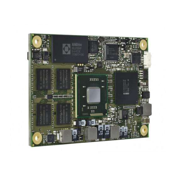
The COM Express® mini sized Computer-on-Module COMe-mCT10 (NUP1) follows pin-out Type 10 and is compatible to PICMG specification COM.0 Rev 2.0. The COMe-mCT10, based on Intel's Cedar Trail platform, is available in different variants to cover the demand of different performance, price and power: Commercial grade modules (0°C to 60°C operating) - Page 11 Cooling & Mounting 34005-0000-99-0 HSP COMe-mCT10 thread (11mm) 34005-0000-99-1 HSP COMe-mCT10 through (11mm) 34005-0000-99-2 HSP COMe-mCT10 slim thread (6.5mm) 34005-0000-99-3 HSP COMe-mCT10 slim though (6.5mm) 34099-0000-99-0 COMe mini Active Uni Cooler (for CPUs up to 10W) (Note1) 34099-0000-99-1 COMe mini Passive Uni Cooler (for CPUs up to 5W)
-
Page 12: Functional Specification
Functional Specification Processor The 32nm Intel® ATOM™ (Cedarview) CPU family supports: » Intel® Hyper-Threading Technology » Intel® 64 » Enhanced Intel SpeedStep® Technology (N2xxx only) » Thermal Monitoring Technologies » Execute Disable Bit » 2 Display Pipes for dual independent displays CPU specifications Intel®... - Page 13 Graphics Core The integrated SGX545 core based Intel® GMA 3650 / 3600 supports: 640MHz @ GMA3650 (D2700/N2800), 400MHz @ GMA3600 (N2600), Graphics Core Render Clock Execution Units / Pixel Pipelines Max Graphics Memory 1024MB GFX Memory Bandwidth (GB/s) 6.4 / 8.5 GFX Memory Technology DVMT 9.0c / 3.0...
- Page 14 Onboard Hardware Monitor Nuvoton NCT7802Y Trusted Platform Module Infineon TPM 1.2 SLB9635TT optional Miscellaneous 2x UART optional / PWM FAN Kontron Features External I2C Bus Fast I2C, MultiMaster capable M.A.R.S. support Embedded API PICMG EAPI / JIDA32 Custom BIOS Settings / Flash Backup...
- Page 15 Memory performance are available in Application Note KEMAP054 EMD Customer Section. Supported Operating Systems The COMe-mCT10 supports: » Microsoft Windows XP x86 » Microsoft Windows XPembedded » Microsoft Windows 7 x86 » Microsoft Windows Embedded Standard 7 (WES7) » Linux...
-
Page 16: Block Diagram
Block Diagram... -
Page 17: Electrical Specification
» Maximum 100 mV peak to peak 0 – 20 MHz 3.4.4 Power Consumption The maximum Power Consumption of the different COMe-mCT10 variants is 6.2 - 12.4W (100% CPU load on all cores; 90°C CPU temperature). Further information with detailed measurements are available in Application Note KEMAP054 available EMD Customer... -
Page 18: Atx Mode
3.4.5 ATX Mode By connecting an ATX power supply with VCC and 5VSB, PWR_OK is set to low level and VCC is off. Press the Power Button to enable the ATX PSU setting PWR_OK to high level and powering on VCC. The ATX PSU is controlled by the PS_ON# signal which is generated by SUS_S3# via inversion. -
Page 19: Power Control
Power Control Power Supply The COMe-mCT10 supports a power input from 4.75 - 14V. The supply voltage is applied through the VCC pins (VCC) of the module connector. Power Button (PWRBTN#) The power button (Pin B12) is available through the module connector described in the pinout list. To start the module via Power Button the PWRBTN# signal must be at least 50ms (50ms ≤... -
Page 20: Environmental Specification
-40°C to +85°C -40°C to +85°C See available module variants in chapter Product Specification With Kontron Embedded Modules GmbH heatspreader plate assembly The operating temperature defines two requirements: » the maximum ambient temperature with ambient being the air surrounding the module. -
Page 21: Standards And Certifications
Standards and Certifications RoHS The COMe-mCT10 is compliant to the directive 2002/95/EC on the restriction of the use of certain hazardous substances (RoHS) in electrical and electronic equipment. CE marking The COMe-mCT10 is CE marked according to Low Voltage Directive 2006/95/EC – Test standard EN60950 Component Recognition UL 60950-1 The COM Express®... - Page 22 The COM Express® mini form factor Computer-on-Modules successfully passed shock and vibration tests according to » IEC/EN 60068-2-6 (Non operating Vibration, sinusoidal, 10Hz-4000Hz, +/-0.15mm, 2g) » IEC/EN 60068-2-27 (Non operating Shock Test, half-sinusoidal, 11ms, 15g) Validated in Kontron reference housing for EMC the COMe-mCT10 follows the requirements for electromagnetic compatibility standards » EN55022...
-
Page 23: Mtbf
Estimated RTC battery life (as opposed to battery failures) is not accounted for in the above figures and need to be considered for separately. Battery life depends on both temperature and operating conditions. When the Kontron unit has external power; the only battery drain is from leakage paths. -
Page 24: Mechanical Specification
Mechanical Specification 3.9.1 Module Dimension » 55mm x 84mm (±0.2mm) 3.9.2 Height on Top » Maximum approx. 3.5mm (withouth printed circuit board) » Height is depending on (optional) CPU cooler / heat spreader 3.9.3 Height on Bottom » Maximum approx. 3.5mm (without printed circuit board) 3.9.4 Mechanical Drawing All dimensions are shown in millimeters. -
Page 25: Thermal Management
The aluminum slugs and thermal pads on the underside of the heatspreader assembly implement thermal interfaces between the heatspreader plate and the major heat-generating components on the COMe-mCT10. About 80 percent of the power dissipated within the module is conducted to the heatspreader plate and can be removed by the cooling solution. -
Page 26: Onboard Fan Connector
3.12 Onboard Fan Connector Variants with D2550 and N2800 are equipped with an onboard FAN connector for active cooling controlled by the BIOS. Location of the FAN Connector on top Specification of the FAN Connector: » Part number (Molex) J3: 53261-0390 »... -
Page 27: Features And Interfaces
4 Features and Interfaces Onboard SSD The COMe-mCT10 features an onboard Greenliant SATA NAND flash drive with capacities of 2 to 64GB . Due to performance and longevity reasons standard variants with onboard flash use SLC type only. The following SATA NANDrives are... -
Page 28: S5 Eco Mode
S5 Eco Mode Kontron’s new high-efficient power-off state S5 Eco enables lowest power-consumption in soft-off state – less than 1 mA compared to the regular S5 state this means a reduction by at least factor 200! In the “normal” S5 mode the board is supplied by 5V_Stb and needs usually up to 300mA just to stay off. This mode allows to be switched on by power button, RTC event and WakeOnLan, even when it is not necessary. -
Page 29: Lpc
LPC. This leads to limitations for ISA bus and SIO (standard I/O´s like Floppy or LPT interfaces) implementations. All Kontron COM Express® Computer-on-Modules imply BIOS support for following external baseboard LPC Super I/O controller features for the Winbond/Nuvoton 5V 83627HF/G and 3.3V 83627DHG-P:... -
Page 30: Serial Peripheral Interface (Spi)
The SPI interface can only be used with a SPI flash device to boot from external BIOS on the baseboard. SPI boot The COMe-mCT10 supports boot from an external SPI Flash. It can be configured by pin A34 (BIOS_DIS#0) and pin B88 (BIOS_DIS1#) in following configuration: BIOS_DIS0#... -
Page 31: M.a.r.s
M.A.R.S. The Smart Battery implementation for Kontron Computer-on-Modules called Mobile Application for Rechargeable Systems is a BIOS extension for external Smart Battery Manager or Charger. It includes support for SMBus charger/selector Linear Technology LTC1760 Dual Smart Battery System Manager and provides ACPI compatibility to report battery information to... -
Page 32: Fast I2C
Fast I2C The COMe-mCT10 supports a CPLD implemented LPC to I2C bridge using the WISHBONE I2C Master Core provided from opencores.org. The I2C Interface supports transfer rates up to 40kB/s and can be configured in Setup Specification for SER0/SER1: » Speed up to 400kHz »... -
Page 33: Eapi, Jida & Pld Driver
EAPI, JIDA & PLD Driver K-Station 2 including the Kontron PLD / Board Driver for new generation modules is a replacement for former JIDA16/JIDA32 BIOS implementations. It consists of hardware drivers providing access to features like Watchdog, I2C Bus or GPIO implemented in the onboard Programmable Logic Device (CPLD). The Board Driver supports the official PICMG embedded API (EAPI) and for backwards compatibility the former used Kontron JIDA32 API. -
Page 34: K-Station 2
Based on the JIDA32 interface users can implement advanced board functionality in their application. As an example utility Kontron provides K-Station 2 for 32 and 64bit Windows XP, Vista or 7. K-Station 2 is a summary of command line utilities (Shell Tools) for easy access to JIDA32 interface provide by the PLD Board Driver. Second part of K-Station is a JAVA based example GUI which gives a view an all available features using the Shell Tools. -
Page 35: Gpio - General Purpose Input And Output
4.10 GPIO - General Purpose Input and Output The COMe-mCT10 offers 4 General Purpose Input (GPI) pins and 4 General Purpose Output (GPO) pins. On a 3.3V level digital in- and outputs are available. Signal Description GPI0 General Purpose Input 0... -
Page 36: Dual Staged Watchdog Timer
“feeding the watchdog” or “triggering the watchdog”). The intention is to bring the system back from the nonresponsive state into normal operation. The COMe-mCT10 offers a watchdog which works with two stages that can be programmed independently and used one by one. -
Page 37: Speedstep Technology
4.12 Speedstep Technology The Intel® processors offers the Intel® Enhanced SpeedStep™ technology that automatically switches between maximum performance mode and battery-optimized mode, depending on the needs of the application being run. It let you customize high performance computing on your applications. When powered by a battery or running in idle mode, the processor drops to lower frequencies (by changing the CPU ratios) and voltage, conserving battery life while maintaining a high level of performance. -
Page 38: C-States
4.13 C-States New generation platforms include power saving features like SuperLFM, EIST (P-States) or C-States in O/S idle mode. Activated C-States are able to dramatically decrease power consumption in idle mode by reducing the Core Voltage or switching of parts of the CPU Core, the Core Clocks or the CPU Cache. Following C-States are defined: C-State Description... -
Page 39: Hyper Threading
4.14 Hyper Threading Hyper Threading (officially termed Hyper Threading Technology or HTT) is an Intel®-proprietary technology used to improve parallelization of computations performed on PC´s. Hyper-Threading works by duplicating certain sections of the processor—those that store the architectural state but not duplicating the main execution resources. This allows a Hyper- Threading equipped processor to pretend to be two “logical”... -
Page 40: Acpi Suspend Modes And Resume Events
4.15 ACPI Suspend Modes and Resume Events The COMe-mCT10 supports the S3 state (=Save to Ram). S4 (=Save to Disk) is not supported by the BIOS (S4_BIOS) but S4_OS is supported by the following operating systems: » Windows XP » Windows Vista »... -
Page 41: System Resources
5 System Resources Interrupt Request (IRQ) Lines IRQ # Used For Available Comment Timer0 Keyboard Cascade External SIO - COM2 Ext.SIO Dynamic (BIOS default) External SIO - COM1 Ext.SIO Dynamic (BIOS default) External SIO - LPT1 Ext.SIO Dynamic (BIOS default) Ext.SIO SMBus Note(3) -
Page 42: I/O Address Map
I/O Address Map The I/O-port addresses of the are functionally identical to a standard PC/AT. All addresses not mentioned in this table should be available. We recommend that you do not use I/O addresses below 0100h with additional hardware for compatibility reasons, even if available. -
Page 43: Sdvo I2C Bus
SDVO I2C Bus I2C Address Used For Available Comment System Management (SM) Bus Address Device Comment SMART_CHARGER Not to be used with any SM bus deivce except a charger SMART_SELECTOR Not to be used with any SM bus deivce except a selector SMART_BATTERY Not to be used with any SM bus deivce except a battery HWMonitor... -
Page 44: Pinout List
Pinout List 5.9.1 General Signal Description Type Description I/O-3,3 Bi-directional 3,3 V IO-Signal I/O-5T Bi-dir. 3,3V I/O (5V Tolerance) I/O-5 Bi-directional 5V I/O-Signal I-3,3 3,3V Input I/OD Bi-directional Input/Output Open Drain I-5T 3,3V Input (5V Tolerance) Output Analog Output Open Drain O-1,8 1,8V Output O-3,3... -
Page 45: Connector X1A Row A
5.9.2 Connector X1A Row A Signal Description Type Termination Comment GND_1 Power Ground GBE0_MDI3- Ethernet Receive Data- DP-I GBE0_MDI3+ Ethernet Receive Data+ DP-I GBE0_LINK100# Ethernet Speed LED 100Mbps GBE0_LINK1000# Ethernet Speed LED 1000Mbps GBE0_MDI2- Ethernet Receive Data- DP-I GBE0_MDI2+ Ethernet Receive Data+ DP-I GBE0_LINK# LAN Link LED... - Page 46 GND_9 Power Ground SDIO_D2 / GPI2 SDIO#0 Data2 / General Purpose Input 2 I/O-3.3 PU 10k/100k to V3.3_S0 PCIE_TX0+ PCIe lane #0 Transmit+ DP-O PCIE_TX0- PCIe lane #0 Transmit- DP-O GND_10 Power Ground LVDS_A0+ LVDS Channel A DAT0+ DP-O LVDS_A0- LVDS Channel A DAT0- DP-O LVDS_A1+...
-
Page 47: Connector X1A Row B
5.9.3 Connector X1A Row B Signal Description Type Termination Comment GND_16 Power Ground GBE0_ACT# Ethernet Activity LED LPC_FRAME# LPC Frame Indicator O-3.3 LPC_AD0 LPC Address / Data Bus IO-3.3 PU 20k in NM10 LPC_AD1 LPC Address / Data Bus IO-3.3 PU 20k in NM10 LPC_AD2 LPC Address / Data Bus... - Page 48 WAKE0# PCI Express Wake Event I-3.3 PU 1k 3.3V_S5 WAKE1# General Purpose Wake Event I-3.3 PU 10k 3.3V_S5 PCIE_RX0+ PCIe lane #0 Receive+ DP-I PCIE_RX0- PCIe lane #0 Receive- DP-I GND_23 Power Ground DDI0_PAIR0+ DDI Data+ Pair 0 DP-O DDI0_PAIR0- DDI Data- Pair 0 DP-O DDI0_PAIR1+...
-
Page 49: Bios Operation
6 BIOS Operation The module is equipped with AMI® Aptio, which is located in an onboard SPI serial flash memory. Determining the BIOS Version The AMI® Aptio version is displayed in the main menu of the setup utility. » BIOS Vendor: American Megatrends »... -
Page 50: Setup Guide
Backup the BIOS / Create a BIOS with custom defaults: » Change your BIOS settings according your needs » Save and Exit Setup with option “Save as User Defaults”. Your customized settings are now stored inside the flash in a second area additional to the manufacturer defaults »... - Page 51 Menu Bar The menu bar at the top of the window lists different menus. Use the left/right arrow keys to make a selection. Legend Bar Use the keys listed in the legend bar on the bottom to make your selections or exit the current menu. The table below describes the legend keys and their alternates.
-
Page 52: Bios Setup
BIOS Setup 6.4.1 Main Menu Feature Option Description System Language English Choose the system default language (English only) System Date [mm-dd-yyyy] <Tab>, <Shift-Tab>, or <Enter> selects field System Time [hh:mm:ss] <Tab>, <Shift-Tab>, or <Enter> selects field... - Page 53 Platform Information...
-
Page 54: Advanced
6.4.2 Advanced... - Page 55 ACPI Settings Feature Options Description Enable ACPI Auto Congiguration Disabled Enables or Disables BIOS ACPI Auto Configuration Enabled Enable Hibernation Disabled Enables or Disables System ability to Hibernate (OS/S4 Enabled Sleep State) ACPI Sleep State Suspend Disabled Select the highest ACPI sleep state the system will enter when the SUSPEND button is pressed S3 (StR) Lock Legacy Ressources...
- Page 56 Trusted Computing (default, without TPM) Feature Options Description Security Device Support Disable Enable or Disable BIOS support for security device. O.S. will not show Security Device. TCG EFI protocol and Enable INT1A interface will not be available...
- Page 57 Trusted Computing (with TPM Option) Feature Options Description TPM Support Disable Enables or Disables TPM support. O.S. will not show Security Device. TCG EFI protocol and INT1A interface Enable will not be available TPM State Disabled Enable/Disable Security Device. Note: Your Computer will reboot during restart in order to change Sate of the Enabled Device...
- Page 58 CPU Configuration Feature Options Description Hyper-Threading Disabled Enables/Disables the Intel® Hyper Threading Enabled Technology HTT Execute Disable Bit Disabled XD can prevent certain classes of malicious buffer Enabled overflow attacks when combined with a supporting OS Limit CPUID Maximum Disabled Disabled for Windows XP Enabled Additional setup option for Cedarview-M (N2600/N2800)
- Page 59 Miscellaneous Feature Options Description S5 Eco Disabled Reduce supply current in Soft Off State S5 to less than 1mA. If enabled, power button is the only wakeup Enabled source in S5. See chapter S5 Eco for more details Reset Button Behavior Chipset Reset Select the behavior of Reset Button.
- Page 60 Watchdog Feature Options Description Auto-reload Disabled Enable automatic reload of watchdog timers on timeout Enabled Global Lock Disabled If set to enabled, all Watchdog registers (except Enabled WD_KICK) become read only until the board is reset Stage 1 Mode Disabled Select Action for first Watchdog stage Reset Delay...
- Page 61 Clock Control Feature Options Description Spread Spectrum Disabled Enable/Disable Spread Spectrum for CPU, DMI, PCIe -0.50% Spread LCD Spread Spectrum Disabled Enable/Disable Spread Spectrum for LCD -2.50 Spread...
- Page 62 LAN Configuration Feature Options Description Onboard LAN Controller Enabled Enable/Disable onboard LAN Controller Disabled Network OpROMs Disabled Enable/Disable Legacy Boot Option for Network Devices Onboard only Addon cards only Both...
- Page 63 Generic LPC Decode Ranges Feature Options Description Generic LPC Decode Range 1 Enabled Enable/Disable Generic LPC Decode Range Generic LPC Decode Range 2 Disabled Generic LPC Decode Range 3 Base Address 0100h Base address of the generic decode range. Valid between 0100h - FFF0h.
- Page 64 Smart Battery Configuration Feature Options Description M.A.R.S. Disabled Preset M.A.R.S. Smart Battery System mode. System must be restarted to reflect mode changes AUTO Charger Manager...
- Page 65 Battery Information...
- Page 66 Onboard I2C Speed Feature Options Description Onboard I2C Speed 1kHz Select Onboard I2C Bus Speed in kHz, min 1kHz, max 10kHz 400kHz 50kHz 100kHz 200kHz 400kHz...
- Page 67 Thermal Configuration...
- Page 68 CPU Thermal Configuration Feature Options Description DTS SMM Disabled Thermal management uses DTS SMM mechanism to optain CPU temperature values. Active/Passive Cooling Enabled is not working if disabled...
- Page 69 Platform Thermal Configuration Feature Options Description Critical Trip Point This value controls the temperature of the ACPI Critical Trip Point - the point in which the OS will shut the 15 .. 127 system off. Note: 100C is the Plan Of Record (POR) for all Intel mobile processors...
- Page 70 IDE Configuration Feature Options Description SATA Controller(s) Disabled Enable/Disable the SATA controller Enabled Configure SATA as Select a configuration for SATA controller AHCI Port0 Speed Limitation No Limit Select AHCI Speed Limit Port1 Speed Limitation GEN1 Rate GEN2 Rate SATA Port 0 Disabled Enable/Disable the SATA Port SATA Port 1...
- Page 71 USB Configuration Feature Options Description Legacy USB Support Enabled Enables Legacy USB support. AUTO option disables legacy support if no USB devices are connected. Disabled DISABLE option will keep USB devices available only for AUTO EFI applications. EHCI Hand-off Enabled This is a workaround for OSes without EHCI hand-off Disabled Support.
- Page 72 SMART Settings Feature Options Description SMART Self Test Disabled Run SMART Self Test on all HDDs during POST Enabled...
- Page 73 W83627H Super IO Configuration This setup option is available if a LPC SuperI/O Nuvoton 83627 is present on the baseboard. By default the COMe-mCT10 supports the legacy interfaces of a 5V 83627HF(J) or 3.3V 83627DHG-P on external LPC. The SIO hardware monitor is not...
- Page 74 Serial Port 0 Configuration Feature Options Description Serial Port Disabled Enable or Disable Serial Port (COM) 0 Enabled Change Settings AUTO Select an optimal setting for SuperIO device. IO=3F8h; IRQ=4; IO=3F8h, IRQ=3,4,5,6,7,9,10,11,12; IO=2F8h, IRQ=3,4,5,6,7,9,10,11,12; IO=3E8h, IRQ=3,4,5,6,7,9,10,11,12; IO=2E8h, IRQ=3,4,5,6,7,9,10,11,12; Device Mode Standard Serial Port Mode Change the Serial Port mode.
- Page 75 Serial Port 1 Configuration Feature Options Description Serial Port Disabled Enable or Disable Serial Port (COM) 1 Enabled Change Settings AUTO Select an optimal setting for SuperIO device. IO=2F8h; IRQ=3; IO=3F8h, IRQ=3,4,5,6,7,9,10,11,12; IO=2F8h, IRQ=3,4,5,6,7,9,10,11,12; IO=3E8h, IRQ=3,4,5,6,7,9,10,11,12; IO=2E8h, IRQ=3,4,5,6,7,9,10,11,12; Device Mode Standard Serial Port Mode Change the Serial Port mode.
- Page 76 Parallel Port Configuration Feature Options Description Parallel Port Disabled Enable or Disable the Parallel Port (LPT/LPTE) Enabled Change Settings AUTO Select an optimal setting for SuperIO device. IO=378h; IRQ=5; IO=378h, IRQ=5,6,7,9,10,11,12; IO=278h, IRQ=5,6,7,9,10,11,12; IO=3BCh, IRQ=5,6,7,9,10,11,12; IO=378h; IO=278h; IO=3BCh; Device Mode STD Printer Mode Change the Printer Port mode.
- Page 77 H/W Monitor Feature Options Description CPU (DTS) xx°C Shows the calculated temperature of Tcasemax - Digital Thermal Sensor PCB (LTD) xx°C Shows the internal hardwaremonitor temperature CPU FAN xxxx RPM Shows the fan speed of onboard FAN connector - CPU Fan Pulse Select the number of pulses the CPU fan produces during one revolution - FAN Control...
- Page 78 Serial Port Console Redirection Serial Port Console Redirection Feature Options Description Console Redirection Disabled Enable/Disable Serial Port COM0 Console Redirection Enabled Console Redirection Disabled Enable/Disable Serial Port COM1 Console Redirection Enabled Console Redirection Disabled Enable/Disable Serial Port COM2 Console Redirection Enabled Console Redirection Disabled...
- Page 79 Console Redirection Settings Feature Options Description Terminal Type VT100 VT100: ASCII char set. VT100+ VT100+: Extends VT100 to support color, function keys, VT_UTF8 etc. ANSI VT-UTF8: Uses UTF8 encoding to map Unicode chars onto 1 or more bytes ANSI: Extended ASCII char set. Bits per second 9600 Selects serial port transmission speed.
-
Page 80: Chipset
6.4.3 Chipset... - Page 81 Host Bridge...
- Page 82 Memory Frequency and Timing Feature Options Description MRC Fast Boot Disabled Enable/Disable MRC fast boot Enabled Max TOLUD Dynamic Maximum Value of TOLUD. Dynamic assignment would adjust TOLUD automatically based on largest MMIO length of installed graphic controller 1.25GB 1.5GB 1.75GB 2.25GB 2.5GB...
- Page 83 Intel IGD Configuration Feature Options Description Prim IGFX Boot Display AUTO Select the Integrated Grahics Video Device which will be activated during POST. This has no effect if external LVDS graphics devices are present. EFP1 Sec IGFX Boot Display Disabled Select Secondary Integrated Grahics Display Device LVDS EFP1...
- Page 84 South Bridge Feature Options Description PCIe ExpressCard0 Port 0 Controls PCIe Port for ExpressCard support Port 1 Port 2 Port 3 Disabled PCIe ExpressCard1 Port 0 Controls PCIe Port for ExpressCard support Port 1 Port 2 Port 3 Disabled DMI Link ASPM Control Disabled The control of Active State Power Management on both Enabled...
- Page 85 TPT (Tigerpoint IO Hub) Devices Feature Options Description Azalia Controller Disabled Enable/Disable the HD Audio Controller HD Audio Azalia PME Enable Disabled Enable/Disable Power Management capability of Audio Controller Enabled Azalia Vci Enable Disabled Azalia supports 1 extended VC, which, when enabled, Enabled overrides ICH VCp settings USB Function...
- Page 86 PCI Express Root Port 0/1/2 Feature Options Description PCI Express Root Port Disabled Enable/Disable the PCI Express Root Port Enabled Port x IOxAPIC Disabled Enable/Disable PCI Express Root Port I/O APIC Enabled Automatic ASPM Manual Automatically enable ASPM based on reported Auto capabilities and known issues ASPM L0s...
- Page 87 PCI Express Root Port 3 - GbE Feature Options Description PCI Express Root Port 3 Disabled Enable/Disable PCI Express Root Port 3 Enabled Auto...
-
Page 88: Boot
6.4.4 Boot Feature Options Description Setup Prompt Timeout Number of seconds to wait for setup activation key. 65535 (0xFFFF) means idefinite waiting. 0 means no wait (not recommended) Bootup NumLock State Select the keyboard NumLock state Quiet Boot Disabled Enables/Disables Quiet Boot option (Boot logo) Enabled Fast Boot Disabled... -
Page 89: Security
6.4.5 Security Feature Options Description Administrator Password Set the Administrator Password for Setup Access User Password Set User Password HDDx Set HDD Password... - Page 90 Set HDD Password Feature Options Description Set User Password Set HDD User Password. Advisable to Power Cycle System after Setting Hard Disk Passwords...
-
Page 91: Save & Exit
6.4.6 Save & Exit Feature Options Description Save Changes and Exit Exit system setup after saving the changes Discard Changes and Exit Exit system setup without saving any changes Save Changes and Reset Reset system after saving the changes Discard Changes and Reset Reset system without saving any changes Save Changes Save changes made so far to any of the setup options... - Page 92 188 Southern West 4th Ring Germany Beijing 100070, P.R.China Tel.: +49 (0)8165/ 77 777 Tel.: +1 888 294 4558 Tel.: + 86 10 63751188 Fax: +49 (0)8165/ 77 219 Fax: +1 858 677 0898 Fax: + 86 10 83682438 info@kontron.com info@us.kontron.com info@kontron.cn...
Need help?
Do you have a question about the COMe-mCT10 and is the answer not in the manual?
Questions and answers