Table of Contents
Advertisement
Quick Links
Advertisement
Table of Contents

Related Manuals for Kontron COMe-mAL10


Summary of Contents for Kontron COMe-mAL10
- Page 1 USER GUIDE COMe-mAL10 Doc. User Guide, Rev. 1.3 Doc. ID: 1061-1952...
- Page 2 COMe-mAL10 – User Guide, Rev. 1.3 This page has been intentionally left blank www.kontron.com // 2...
- Page 3 In cases of doubt, please contact Kontron. This user guide is protected by copyright. All rights are reserved by Kontron. No part of this document may be reproduced, transmitted, transcribed, stored in a retrieval system, or translated into any language or computer language, in any form or by any means (electronic, mechanical, photocopying, recording, or otherwise), without the express written permission of Kontron.
- Page 4 ENVIRONMENTAL DAMAGE (COLLECTIVELY, "HIGH RISK APPLICATIONS"). You understand and agree that your use of Kontron devices as a component in High Risk Applications is entirely at your risk. To minimize the risks associated with your products and applications, you should provide adequate design and operating safeguards.
- Page 5 If you have any difficulties using this user guide, discover an error, or just want to provide some feedback, contact Kontron support. Detail any errors you find. We will correct the errors or problems as soon as possible and post the revised user guide on our website.
-
Page 6: Symbols
COMe-mAL10 – User Guide, Rev. 1.3 Symbols The following symbols may be used in this user guide. DANGER indicates a hazardous situation which, if not avoided, will result in death or serious injury. WARNING indicates a hazardous situation which, if not avoided, could result in death or serious injury. - Page 7 Therefore, in the interest of your own safety and of the correct operation of your new Kontron product, you are requested to conform with the following guidelines.
- Page 8 General Instructions on Usage In order to maintain Kontron’s product warranty, this product must not be altered or modified in any way. Changes or modifications to the product, that are not explicitly approved by Kontron and described in this user guide or received from Kontron Support as a special handling instruction, will void your warranty.
- Page 9 General Instructions on Usage In order to maintain Kontron’s product warranty, this product must not be altered or modified in any way. Changes or modifications to the product, that are not explicitly approved by Kontron and described in this user guide or received from Kontron’s Technical Support as a special handling instruction, will void your warranty.
-
Page 10: Table Of Contents
2.5.1. Heatspreader Plate (HSP) Assembly and Metal Heat Slug ..................... 27 2.5.2. Active/Passive Cooling Solutions ..............................27 2.5.3. Operating with Kontron Heatspreader Plate (HSP) Assembly....................27 2.5.4. Operating without Kontron Heatspreader Plate (HSP) Assembly ..................27 2.5.5. On-board Fan Connector ................................... 27 2.6. Environmental Specification................................29 2.6.1. - Page 11 COMe-mAL10 – User Guide, Rev. 1.3 2.8.1. Module Dimensions ....................................31 2.8.2. Module Height ......................................31 2.8.3. Heatspreader Dimensions ................................. 31 Features and Interfaces ................................. 33 3.1. eMMC Flash Memory ....................................33 3.2. LPC ..........................................33 3.3. Serial Peripheral Interface (SPI) ................................. 33 3.3.1.
-
Page 12: List Of Tables
Table 5: COMe Type 10 Accessories ................................16 Table 6: General COMe Accessories ................................16 Table 7: Specification of the COMe-mAL10 Processor Variants ....................... 18 Table 8: ATX Mode Settings ..................................26 Table 9: Single Supply Mode Settings ..............................26 Table 10: Heatspreader Temperature Specifications .......................... -
Page 13: 1/ Introduction
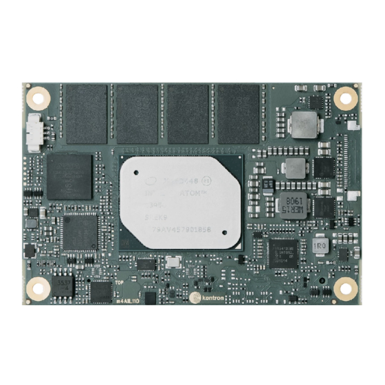
1.1. Product Description The COMe-mAL10 is small form factor COM Express® Type 10 Computer On-Module based on the Intel® Apollo Lake® series of processors Atom™, Pentium® and Celeron®, with an integrated chipset. The COMe-mAL10 combines increased efficiency and performance with TDP as low as 6 W and no more than 12 W, with Intel’s® extensive HD Graphics capabilities. -
Page 14: Com Express® Functionality
1.4. COM Express® Functionality All Kontron COM Express® mini modules contain one 220-pin connector containing two rows called row A & row B. The COM Express® mini Computer-On-Module (COM) features the following maximum amount of interfaces according to the PCI Industrial Computer Manufacturers Group (PICMG) module pinout type. -
Page 15: 2/ Product Specification
2/ Product Specification 2.1. Module Variants The COMe-mAL10 is available in different processor, memory and temperature variants to cover demands in performance, price and power. The following tables list the module variants for the commercial and industrial temperature grade. 2.1.1. -
Page 16: Accessories
COMe-mAL10 – User Guide, Rev. 1.3 2.2. Accessories Accessories are either COMe-mAL10 product specific, Type 10 COMe pinout specific, or general COMe accessories. For more information, contact your local Kontron sales representative or Kontron Inside Sales. Table 4: Product Specific Accessories... -
Page 17: Functional Specifications
COMe-mAL10 – User Guide, Rev. 1.3 2.3. Functional Specifications 2.3.1. Block Diagram COMe-mAL10 The following figure displays the system block diagram applicable to all COMe-mAL10 modules. Figure 1: Block Diagram COMe-mAL10 www.kontron.com // 17... -
Page 18: Processors
Intel® Identity Protection Technology Intel® AES New Instructions Secure Key The following table lists the Intel® Apollo Lake processors specifications compatible with the COMe-mAL10. Table 7: Specification of the COMe-mAL10 Processor Variants Intel® Atom™ Atom® Atom™ Pentium®... -
Page 19: Platform Controller Hub (Pch)
Using DP 1.2 ‘Multi Media Stream Transport’ it is possible to have two independent displays on DDIO. In total, a maximum of three independent displays are possible if including LVDS. The COMe-mAL10 supports the following digital display interfaces (DDIs): ... -
Page 20: Lvds
COMe-mAL10 – User Guide, Rev. 1.3 2.3.5.2. Display Resolution The following table lists the maximum display resolution of the supported display interfaces. Display Interfaces Maximum Resolution 3840 x 2160 @ 60 Hz DP 1.2 (++) 4096 x 2160 @ 60 Hz HDMI 1.4... -
Page 21: Usb
6x USB 2.0 USB Over Current Signals USB Client Port 1x (COMe port 7 can be configured as client port on all COMe-mAL10 variants) The USB 3.0 and USB 2.0 port combinations and the relationship between the COMe connector number and the SoC port number are listed in the following table. -
Page 22: Ethernet
Ethernet The Intel® Ethernet Controllers i210 and i211, both support one Gigabit Ethernet connectivity. Which Ethernet controller is implemented depends on COMe-mAL10’s chosen temperature grade. Both Ethernet controllers include physical layer (PHY) ports supporting Ethernet media dependent interfaces [0-3]. The following table lists the supported Ethernet features. -
Page 23: Storage Features
LID Signals Supported Sleep Signals Supported SMBus Supported 2.3.16. Kontron Features The following table lists the supported Kontron specific product features. External I2C Bus Fast I2C, MultiMaster capable Embedded API KEAPI3 Custom BIOS Settings / Flash Supported Backup Watchdog Support Dual staged www.kontron.com... -
Page 24: Electrical Specification
2.4. Electrical Specification 2.4.1. Power Supply Voltage Specification The COMe-mAL10 supports operation in both single supply power supply mode and ATX power supply mode. The following table lists the power supply voltage specifications. Supply Voltage (VCC) 12 V Standby Voltage 5 V ±5 %... -
Page 25: Power Supply Control Settings
BIOS switch “After Power Fail” is set to “Stay Off”. The COMe-mAL10 includes an additional cold reset during the first cold boot after a complete power loss (including battery voltage). This additional reset will not happen on any subsequent warm or cold reboots. -
Page 26: Table 8: Atx Mode Settings
COMe-mAL10 – User Guide, Rev. 1.3 The following table provides the ATX mode settings. Table 8: ATX Mode Settings State PWRBTN# PWR_OK V5_StdBy PS_ON# high high S5 → S0 low → high high → PWRBTN Event 0V→ VCC high high x –... -
Page 27: Thermal Management
COM Express® application and environmental conditions. Active or passive cooling solutions provided from Kontron for the COMe-mAL10 are usually designed to cover the power and thermal dissipation for a commercial temperature range used in housing with proper airflow. For more information concerning possible cooling solutions, see Table 6: General COMe Accessories. -
Page 28: Table 11: 3-Pin Fan Connector Pin Assignment
COMe-mAL10 – User Guide, Rev. 1.3 Table 11: 3-Pin Fan Connector Pin Assignment Signal Description Type Fan_Tach_IN# Input voltage V_FAN Limited to max. 12 V (±10%) across the whole input range Power GND To connect a standard 3-pin connector fan to the module, use one of the following adaptor cables: ... -
Page 29: Environmental Specification
COMe-mAL10 – User Guide, Rev. 1.3 2.6. Environmental Specification Kontron defines the operating and non-operating temperature grades for the COMe-mAL10. For more temperature grade information, see Chapter 2.1 Module Variants. Table 13: Temperature Grade Specifications Temperature Grades Operating Non-operating (Storage temperature) Commercial Grade 0°C to +60°C... -
Page 30: Standards And Certifications
COMe-mAL10 – User Guide, Rev. 1.3 2.7. Standards and Certifications The COMe-mAL10 complies with the following standards and certifications. For more information, contact Kontron Support. Emission EN55022: Class B (EMC) Information technology equipment, - Radio disturbance characteristics- Limits and methods... -
Page 31: Mechanical Specification
COMe-mAL10 – User Guide, Rev. 1.3 2.8. Mechanical Specification The COMe-mAL10 is compliant with the mechanical specification of the COM Express® PICMG COM.0 Rev 2.1. 2.8.1. Module Dimensions The dimensions of the module are: 84 mm x 55 mm (3.3“ x 2.17“) Figure 2: Module Dimensions *All dimensions are in mm. -
Page 32: Figure 3: Heatspreader And Metal Heat Slug Dimensions
COMe-mAL10 – User Guide, Rev. 1.3 For industrial temperature grade variants the CPU comes with a preconfigured heatspreader and the supplied metal heat slug is not required. Figure 3: Heatspreader and Metal Heat Slug Dimensions Metal heat slug Location of the metal heat slug *All dimensions shown in mm. -
Page 33: 3/ Features And Interfaces
An optional embedded Multimedia Flash Card (eMMC) complying with the eMMC 5.0 specification can be permanently attached to the module, allowing for a capacity of up to 64 GByte NAND Flash. During the COMe-mAL10’s manufacturing process, Multi Level Cell (MLC) eMMC is reconfigured to act as pseudo Single Level Cell (pSLC) eMMC to provide improved reliability, endurance and performance. -
Page 34: Spi Boot
Boot from external SPI Flash chip and flash the external SPI Flash chip The COMe-mAL10 supports boot from an external 16 MB, 3 V serial SPI Flash, where pin A34 (BIOS_DIS0#) and pin B88 (BIOS_DIS1#) configure the SPI Flash as shown in Table 16: SPI Boot Pin Configuration. -
Page 35: External Spi Flash On Modules With Intel® Management Engine
If disconnecting and reconnecting the same module again, this step is not necessary. 3.4. Fast I2C Fast I2C supports transfer between components on the same board. The COMe-mAL10 features an embedded I2C controller connected to the LPC Bus. -
Page 36: 3.6.1. Watchdog Timer Signal
COMe-mAL10 – User Guide, Rev. 1.3 The COMe-mAL10 offers a watchdog that works with two stages that can be programmed independently and used stage by stage. Table 18: Dual Staged Watchdog Timer- Time-Out Events 0000b No action The stage is off and will be skipped. -
Page 37: 3.10. Kontron Security Solution
The Kontron Security Solution feature is available on request and offers a hardware and software solution that includes an embedded hardware security module and a software framework to protect applications. On request, the COMe-mAL10 can be equipped with a security chip connected to SoC port 7 (= COMe USB6). Integrated security solution features are: Copy protection ... -
Page 38: 4/ System Resources
COMe-mAL10 – User Guide, Rev. 1.3 4/ System Resources 4.1. Interrupt Request (IRQ) Lines The following table specifies the device connected to each Interrupt line or if the line is available for new devices. Table 19: Interrupt Requests General Usage... -
Page 39: I/O Address Map
COMe-mAL10 – User Guide, Rev. 1.3 4.3. I/O Address Map The I/O port addresses are functionally identical to a standard PC/AT. All addresses not mentioned in this table should be available. We recommend that you do not use I/O addresses below 0100h with additional hardware, for compatibility reasons, even if the I/O address is available. -
Page 40: Peripheral Component Interconnect (Pci) Devices
COMe-mAL10 – User Guide, Rev. 1.3 I/O Address Range General Usage Project Usage 300-301 MIDI Not used 300-31F System specific peripherals Not used 370-377 Floppy disk controller Not used 376-377 HDD-Controller IDE1 Slave Not used 378-37F Parallel port LPT 1... -
Page 41: System Management (Sm) Bus
COMe-mAL10 – User Guide, Rev. 1.3 4.6. System Management (SM) Bus The 8-bit SMBus address uses the LSB (Bit 0) for the direction of the device. Bit0 = 0 defines the write address Bit0 = 1 defines the read address The 8-bit address listed below shows the write address for all devices. -
Page 42: 5/ Come Interface Connector
5/ COMe Interface Connector The COMe-mAL10 supports one COMe Interface connector (X1A) that is mounted on the bottom side of the module and contains two rows: row A (1-100) and row B (1-100). The figure below shows the position of the connectors and indicates the first pin in row A. -
Page 43: Table 24: General Signal Description
COMe-mAL10 – User Guide, Rev. 1.3 Table 24: General Signal Description Type Description Type Description O-1,8 Not Connected (on this product) 1.8 V Output I/O-3,3 O-3,3 Bi-directional 3.3 V I/O-Signal 3.3 V Output I/O-5T Bi-dir. 3.3 V I/O (5 V Tolerance) -
Page 44: Connector X1A Row A 1 - A110
COMe-mAL10 – User Guide, Rev. 1.3 5.1.1. Connector X1A Row A 1 - A110 Table 25: Connector X1A Row A Pin Assignment (A1-A110) COMe Signal Description Type Termination Comment Power Ground PWR GND GBE0_MDI3- Ethernet Media Dependent Interface 3 DP-I/O... - Page 45 COMe-mAL10 – User Guide, Rev. 1.3 COMe Signal Description Type Termination Comment HDA_SDOUT HD Audio Serial Data Out O-3.3 BIOS_DIS0# BIOS selection straps 0 I-3.3 PU 10 kΩ, 3.3 V (S5) determines the BIOS boot device THRMTRIP# Thermal Trip indicates CPU has entered O-3.3...
- Page 46 COMe-mAL10 – User Guide, Rev. 1.3 COMe Signal Description Type Termination Comment Power Ground PWR GND GPI2 General purpose input 2 I-3.3 PU 20 kΩ, 3.3 V (S0) PCIE_TX0+ PCI Express transmit lane 0 DP-O PCIE_TX0- Power Ground PWR GND...
- Page 47 COMe-mAL10 – User Guide, Rev. 1.3 COMe Signal Description Type Termination Comment A101 SER1_TX Serial port 1 TXD O-3.3 20 V protection circuit implemented on- module, PD on carrier boards needed for proper operation A102 SER1_RX Serial port 1 RXD...
-
Page 48: Connector X1A Row B1 - B110
COMe-mAL10 – User Guide, Rev. 1.3 5.1.2. Connector X1A Row B1 – B110 Table 26: Connector X1A Row B Pin Assignment (B1-B110) COMe Signal Description Type Termination Comment Power Ground PWR GND GBE0_ACT# Ethernet Controller activity LED indicator LPC_FRAME# Indicates the start of an LPC O-3.3... - Page 49 COMe-mAL10 – User Guide, Rev. 1.3 COMe Signal Description Type Termination Comment Power Ground PWR GND SPKR Speaker output provides the PC O-3.3 beep signal and is mainly intended for debugging purposes I2C_CK I2C port clock output O-3.3 PU 2.21 kΩ, 3.3 V (S5)
- Page 50 COMe-mAL10 – User Guide, Rev. 1.3 COMe Signal Description Type Termination Comment PCIE_RX2+ PCI Express receive lane 2 DP-I PCIE_RX2- GPO3 General purpose output 3 O-3.3 PD 20 KΩ PCIE_RX1+ PCI Express receive lane 1 DP-I PCIE_RX1- WAKE0# PCI Express Wake Event, wake I-3.3...
- Page 51 COMe-mAL10 – User Guide, Rev. 1.3 COMe Signal Description Type Termination Comment DDI0CTRLDATA_AUX- DDIO auxiliary data control PD 100 kΩ, signal 3,3V (S0) B100 Power Ground PWR GND B101 FAN_PWMOUT Fan speed control by PWM O-3.3 20 V protection circuit...
-
Page 52: 6/ Uefi Bios
A Setup menu appears. The COMe-mAL10 uEFI BIOS Setup program uses a hot key navigation system. The hot key legend bar is located at the bottom of the Setup screens. The following table provides a list of navigation hot keys available in the legend bar. -
Page 53: Setup Menus
COMe-mAL10 – User Guide, Rev. 1.3 6.2. Setup Menus The Setup utility features menus listed in the selection bar at the top of the screen are: Main Advanced Chipset Security Boot Save & Exit The currently active menu and the currently active uEFI BIOS Setup item are highlighted in white. -
Page 54: Main Setup Menu
COMe-mAL10 – User Guide, Rev. 1.3 6.2.1. Main Setup Menu On entering the uEFI BIOS, the setup program displays the Main Setup menu. This screen lists the Main Setup menu sub-screens and provides basic system information as well as functions for setting the system language, time and date. -
Page 55: Advanced Setup Menu
COMe-mAL10 – User Guide, Rev. 1.3 6.2.2. Advanced Setup Menu The Advanced Setup menu displays sub-screens and second level sub-screens with functions, for advanced configurations. Setting items, on this screen, to incorrect values may cause system malfunctions. Figure 6: Advanced Setup Menu Initial Screen The following table shows the Advanced sub-screens and functions and describes the content. - Page 56 COMe-mAL10 – User Guide, Rev. 1.3 Sub-Screen Function Second level Sub-Screen / Description Trusted Pending Schedules an operation for security device Note: Computer reboots on Computing> Operation> restart to change the state of the security device. (continued) [None, TPM Clear]...
- Page 57 COMe-mAL10 – User Guide, Rev. 1.3 Sub-Screen Function Second level Sub-Screen / Description Miscellaneous> Reset Button Selects reset button behavior (continued) Behavior> [Chipset Reset, Power Cycle] I2C Speed> Selects internal I2C bus speed between (1 kHz and 400 kHz) For a default system 200 kHz is an appropriate value.
- Page 58 COMe-mAL10 – User Guide, Rev. 1.3 Sub-Screen Function Second level Sub-Screen / Description H/W Monitor> measurement, and does not supply an internal diode on the CPU’s die that can be used instead of PECI. Reading the DTS based values would harm the system’s real-time behavior (continued) and is therefore not used.
- Page 59 COMe-mAL10 – User Guide, Rev. 1.3 Sub-Screen Function Second level Sub-Screen / Description Socket 0 CPU Read only field Configuration> Information> Processor Type, CPU signature, Microcode patch, Max. CPU Speed, Min. CPU speed, processor Cores, Intel HT technology, intel VT-x technology, L1 Data Cache, L1 Code Cache, L2 Cache and L3 Cache.
- Page 60 COMe-mAL10 – User Guide, Rev. 1.3 Sub-Screen Function Second level Sub-Screen / Description P-State Changed P-State coordination type Configuration> Coordinator> [HW_ALL, SW_ALL, SW_ANY] (continued) DTS> Digital thermal sensor [Enabled, Disabled] SIO Configuration> Read only field AMI SIO driver version Serial Port 0>...
- Page 61 COMe-mAL10 – User Guide, Rev. 1.3 Sub-Screen Function Second level Sub-Screen / Description Network Stack Network Stack> UEFI network stack Configuration> [Enabled, Disabled] Ipv4 PXE Enables Ipv4 PXE boot support Support> Note: If disabled IPV4 PXE boot option is not created.
-
Page 62: Chipset Setup Menu
COMe-mAL10 – User Guide, Rev. 1.3 6.2.3. Chipset Setup Menu On entering the Chipset Setup menu, the screen lists four sub-screen options North bridge, South bridge, Uncore Configuration and South Cluster Configuration. 6.2.3.1. Chipset> North Bridge Figure 7: Chipset > North Bridge Menu Initial Screen The following table shows the North bridge sub-screens and functions and describes the content. -
Page 63: Table 31: Chipset Set> South Bridge Sub-Screens And Functions
COMe-mAL10 – User Guide, Rev. 1.3 6.2.3.2. Chipset > South Bridge Figure 8: Chipset>South Bridge Menu Initial Screen The following table shows the South Bridge sub-screens and functions, and describes the content. Default settings are in bold. Table 31: Chipset Set> South Bridge Sub-screens and Functions... -
Page 64: Figure 9: Chipset>Uncore Configuration Menu Initial Screens
COMe-mAL10 – User Guide, Rev. 1.3 6.2.3.3. Chipset> Uncore Configuration Figure 9: Chipset>Uncore Configuration Menu Initial Screens www.kontron.com // 64... -
Page 65: Table 32: Chipset Set> Uncore Configuration Sub-Screens And Functions
COMe-mAL10 – User Guide, Rev. 1.3 The following table shows the Uncore Configuration sub-screens and functions and describes the content. Default settings are in bold. Table 32: Chipset Set> Uncore Configuration Sub-screens and Functions Function Second level Sub-Screen / Description Read only field GOP Configuration data and IGD managed by Intel®... - Page 66 COMe-mAL10 – User Guide, Rev. 1.3 Function Second level Sub-Screen / Description Cd Clock Selects the highest Cd clock frequency supported by the platform Frequency> [144 MHz, 288 MHz, 384 MHz, 576 MHz, 624 MHz] GT PM Support> GT PM Support [Enabled, Disabled] BIA>...
-
Page 67: Table 33: Chipset>South Cluster Configuration Sub-Screens And Functions
COMe-mAL10 – User Guide, Rev. 1.3 6.2.3.4. Chipset> South Cluster Configuration Figure 10: Chipset>South Cluster Configuration Menu Initial Screen The following table shows the South Cluster Configuration sub-screens and functions and describes the content. Default settings are in bold and for some functions, additional information is included. - Page 68 COMe-mAL10 – User Guide, Rev. 1.3 Function Second level Sub-Screen / Description HD Audio HD-Audio Link Selects HD-Audio link frequency Configuration> Frequency> Applicable only if HDA codec supports selected frequency. (continued) [6 MHz, 12 MHz, 24 MHz] iDisplay Link Selects iDisplay Link frequency Frequency>...
- Page 69 COMe-mAL10 – User Guide, Rev. 1.3 Function Second level Sub-Screen / Description PCI Express PCI Root Port 1 SECE> Root PCI Express System Error on Configuration> (GbE)> correctable error (continued) [Enabled, Disabled] PCI Root Port 3 PME SCI> PCI Express PME SCI (COMe PCIe#0)>...
- Page 70 COMe-mAL10 – User Guide, Rev. 1.3 Function Second level Sub-Screen / Description SATA Drivers> SATA Port 0> SATA Port #> Read only field (continued) SATA port installed/Not Installed and software preserve SATA Port 1> Port #> SATA port # [Enabled, Disabled]...
- Page 71 COMe-mAL10 – User Guide, Rev. 1.3 Function Second level Sub-Screen / Description USB Port Disable Selectively enables or disables the corresponding USB port Configuration> Override> from reporting a device connection to the controller. (continued) [Enabled, Disabled] xDCI Support> XDCI [Disable, PCI Mode]...
-
Page 72: Security Setup Menu
COMe-mAL10 – User Guide, Rev. 1.3 6.2.4. Security Setup Menu The Security Setup menu provides information about the passwords and functions for specifying the security settings such as Hard Disk user and master passwords. Figure 11: Security Setup Menu Initial Screen The following table shows the Security sub-screens and functions and describes the content. - Page 73 If the system cannot be booted because the User Password or the Supervisor Password are not known, clear the uEFI BIOS settings, or contact Kontron Support for further assistance. HDD security passwords cannot be cleared using the above method.
-
Page 74: Boot Setup Menu
COMe-mAL10 – User Guide, Rev. 1.3 6.2.5. Boot Setup Menu The Boot Setup menu lists the dynamically generated boot-device priority order. Figure 12: Boot Setup Menu Initial Screen The following table shows the Boot set up sub-screens and functions and describes the content. Default settings are in bold. -
Page 75: Save And Exit Setup Menu
COMe-mAL10 – User Guide, Rev. 1.3 6.2.6. Save and Exit Setup Menu The Save and Exit Setup menu provides functions for handling changes made to the settings and exiting the program. Figure 13: Save and Exit Setup Menu Initial Screen The following table shows the Save and Exit sub-screens and functions and describes the content. -
Page 76: The Uefi Shell
The uEFI Shell The Kontron uEFI BIOS features a built-in and enhanced version of the uEFI Shell. For a detailed description of the available standard shell scripting, refer to the EFI Shell User Guide. For a detailed description of the available standard shell commands, refer to the EFI Shell Command Manual. -
Page 77: Uefi Shell Scripting
Initially searches for Kontron flash-stored startup script. If there is no Kontron flash-stored startup script present, then the uEFI-specified startup.nsh script is used. This script must be located on the root of any of the attached FAT formatted disk drive. - Page 78 COMe-mAL10 – User Guide, Rev. 1.3 On the next start, boot into shell (see Chapter 6.3.1.1 Entering the uEFI Shell). Change to the drive representing the USB stick. fsx: (x = 0,1,2,etc. represents the USB stick) And then change to the directory where you copied the flash tool.
-
Page 79: Table 37: List Of Acronyms
COMe-mAL10 – User Guide, Rev. 1.3 Appendix A: List of Acronyms Table 37: List of Acronyms HBR2 Application Programming Interface High Bitrate 2 BIOS Basic Input Output System High Definition Audio (HD Audio) HD/HDD Base Management Controller Hard Disk /Drive... - Page 80 COMe-mAL10 – User Guide, Rev. 1.3 pSLC pseudo Single Level Cell Power Supply Unit RoHS Restriction of the use of certain Hazardous Substances Real Time Clock Serial Attached SCSI – high speed serial version of SCSI SATA Serial AT Attachment:...
-
Page 81: About Kontron
COMe-mAL10 – User Guide, Rev. 1.3 About Kontron Kontron is a global leader in embedded computing technology (ECT). As a part of technology group S&T Kontron offers a combined portfolio of secure hardware, middleware and services for Internet of Thing (IoT) and Industry 4.0 applications.
Need help?
Do you have a question about the COMe-mAL10 and is the answer not in the manual?
Questions and answers