Table of Contents
Advertisement
Quick Links
Advertisement
Table of Contents

Related Manuals for Kontron EPIC/CE


Summary of Contents for Kontron EPIC/CE
- Page 1 Kontron User's Guide ® EPIC/CE ® Document Revision 1.14...
- Page 2 This page intentionally left blank...
-
Page 3: Table Of Contents
MTBF......................18 Environmental Specifications ................19 4.5.1 Temperature....................19 4.5.2 Humidity ....................... 19 CPU, Chipset and Super I/O ..................20 CPU ......................20 Chipset......................20 5.2.1 GMCH (815E Chipset) ..................20 5.2.2 ICH4 (82801DB)....................22 Super I/O....................... 23 Kontron User's Guide EPIC/CE... - Page 4 Flat Panel LVDS Interface (JILI) Connector ............35 11.5 Display Power Considerations ................36 11.6 Connecting a LCD Panel ..................36 11.7 Configuration ....................37 11.8 Graphics Technical Support ................37 11.9 Available Video Modes..................37 11.9.1 Standard IBM-Compatible VGA Modes..............37 Kontron User's Guide EPIC/CE...
- Page 5 17.2 Programming ....................50 17.2.1 16-Bit Operating Systems ................. 50 17.2.2 32-Bit Operating Systems ................. 52 17.3 Configuration ....................52 FAN Interface......................53 18.1 Connector...................... 53 18.2 Configuration ....................53 Power Interface......................54 19.1 Power Interface Connectors................54 Kontron User's Guide EPIC/CE...
- Page 6 SM Bus Devices ....................66 Appendix B: BIOS Operation ..................67 24.1 Determining the BIOS Version................67 24.2 Configuring the System BIOS ................67 24.2.1 General Information ..................68 24.3 Main Menu ..................... 69 24.3.1 Master or Slave Submenus................. 70 Kontron User's Guide EPIC/CE...
- Page 7 24.7.1 MultiBoot XP ....................82 24.7.2 Boot First Function ..................83 24.8 Exit Menu ......................84 24.9 Kontron BIOS Extensions .................. 84 24.9.1 JIDA BIOS extension ..................85 24.9.2 Remote Control Client Extension ................ 85 24.9.3 LAN PXE ROM ....................85 24.10 Updating or Restoring BIOS Using PhoenixPhlash..........
- Page 8 28.1.2 PC/104, PCI....................99 28.2 General PC Architecture ..................99 28.3 Ports......................100 28.3.1 RS-232 Serial ....................100 28.3.2 ATA ......................100 28.3.3 USB ......................100 28.4 Programming ....................100 Appendix G: Document Revision History ..............101 Kontron User's Guide EPIC/CE viii...
-
Page 9: User Information
“as-is” and is subject to change without notice. For the circuits, descriptions and tables indicated, Kontron assumes no responsibility as far as patents or other rights of third parties are concerned. -
Page 10: Technical Support
Kontron Embedded Modules GmbH will not be responsible for any defects or damages to other products not supplied by Kontron Embedded Modules GmbH that are caused by a faulty Kontron Embedded Modules GmbH product. -
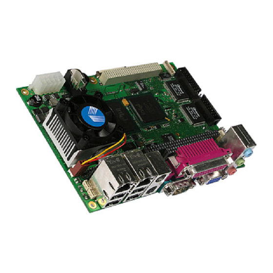
Page 11: Introduction
2 Introduction Introduction EPIC/CE The EPIC/CE hosts either an ULV Intel® Celeron® processor or an LV Intel® Celeron® processor in ® combination with an Intel 815E chipset that includes an integrated graphics memory-controller hub. A SDRAM-SODIMM socket can hold either PC100 or PC133 SODIMM memory modules up to 500MB. Six USB 2.0 ports and two 10/100 MBit Ethernet interfaces extend the standard connectivity of four serial ports,... -
Page 12: Getting Started
3 Getting started Getting started Getting started with the EPIC/CE is very easy. Take the following steps: Turn off the power supply. ® Connect the power supply to the EPIC’s power supply connector. The board is ® available in an AT- (5V-only) or an ATX-version. -
Page 13: Specifications
RS232C serial port (1 DSUB9 on the front; 3 internal, 10-pin headers) ® 16550-compatible ® One port configurable as RS422/485 ® One Parallel Port (LPT1) Enhanced Parallel Port (EPP) and Extended Capabilities Port (ECP) with bi-directional ® capability Floppy Interface Compact Flash Socket Kontron User's Guide EPIC/CE... - Page 14 Phoenix BIOS, 1024KB Flash BIOS NV-EEPROM for CMOS Setup Retention without Battery ® PS/2 Mouse and PS/2 Keyboard Controller Separate connectors ® Watchdog Timer (WDT) Real Time Clock (RTC) with Onboard Battery Supply 26 General Purpose Input/Outputs (GPIOs) Kontron User's Guide EPIC/CE...
-
Page 15: Mechanical Specifications
Height on Top Maximum 32mm (1.26”) ® Height is depending upon DDR SDRAM module and CPU cooler/fan. ® 4.2.5 Height on Bottom Maximum 6.8mm (0.27”) ® 4.2.6 Weight About 340g (full featured version without SDRAM-SODIMM) ® Kontron User's Guide EPIC/CE... -
Page 16: Electrical Specifications
4.3.3 Supply Current (typical) The EPIC/CE is equipped with power-saving features. Different power-consumption tests were executed to give an overview of the electrical conditions for several operational states. The board used a 256MB SDRAM module for test results shown below. An attached hard disk was not supplied through the measurement path, and there was no extension module in the system. -
Page 17: Supply Current (Maximum)
English, German, French, Danish, Finish and Spanish. If the battery is accessible by the end user, it is in the responsibility of the customer to give the corresponding safety instructions in the required language(s). Kontron User's Guide EPIC/CE... -
Page 18: Mtbf
To Be Done ® Notes: Fans shipped with Kontron Embedded Modules GmbH products have an operating life of up to 50,000 hours. The estimates above assumed that a passive heat-sinking arrangement was used instead of a fan. Estimated RTC battery life (as opposed to battery failures) was not accounted for in the above figures and needs separate consideration. -
Page 19: Environmental Specifications
(*) The maximum operating temperature is the maximum measurable temperature on any spot on the module’s surface. You must maintain the temperature according to the above specification. 4.5.2 Humidity Operating: 10% to 90% (non-condensing) ® Non-operating: 5% to 95% (non-condensing) ® Kontron User's Guide EPIC/CE... -
Page 20: Cpu, Chipset And Super I/O
Power-Management Features, including Quick Start, Deep Sleep and Deeper Sleep ® modes, which provide low-power dissipation Chipset ® The chipset of the EPIC/CE consists of the Intel 815E chipset GMCH (Graphics and Memory Controller ® Hub) and the Intel 82801DB ICH-4 (I/O Controller Hub 4). - Page 21 3 Operand Raster Bit BLTs ® 64x64x3 Color Transparent Cursor ® Power-Management Functions Stop Clock Grant and Halt special cycle translation from the host to the hub interface ® ACPI compliant power management ® APIC buffer management ® Kontron User's Guide EPIC/CE...
-
Page 22: Ich4 (82801Db)
Supports PC/PCI DMA and LPC DMA ® Supports DMA collection buffers ® Timers based on 82C54 Power-Management Logic ACPI 2.0 compliant ® Supports PCI PME# ® Low Pin Count (LPC) interface SM (System Management) Bus 2.0 interface Kontron User's Guide EPIC/CE... -
Page 23: Super I/O
Floppy Disk Controller ® PS/2-Keyboard and PS/2-Mouse Interface ® 26 GPIOs ® CPU, Chipset and Super-I/O Configuration See the Advanced Menu and its submenus section in the Appendix B: BIOS chapter for information on setting choices. Kontron User's Guide EPIC/CE... -
Page 24: System Memory
6 System Memory System Memory The EPIC/CE uses a 144-pin Small Outline-Dual Inline Memory Modules (SODIMM) on the bottom side of the board. One socket is available for 3.3 Volt (power level) un-buffered PC-133 or PC-100 Synchronous Dynamic Random Access Memory (SDRAM) of 8, 16, 32, 64, 128, 256 or 512MB. -
Page 25: Isa And Pci Bus Expansion
PC/104 bus and AT ISA bus is identical between C1 - C18 and D1 - D18. 7.1.1 PC/104 Connectors The EPIC/CE features the XT bus and AT bus extension on two, dual-row socket connectors with a 2.54mm x 2.54mm grid (0.1" x 0.1"). The PC-104 bus is available through Connectors J16B and J16C. -
Page 26: Pc/104-Plus (Pci Part)
7 ISA and PCI Bus Expansion PC/104-Plus (PCI part) The EPIC/CE offers the PC/104-Plus bus on a quad-row female connector with a 2mm x 2mm (0.79” x 0.79”) pitch. This connector implements the standard 32-bit PCI bus signals. 7.2.1 PC/104-Plus Connector You can only use PC/104-Plus adapter boards on top of an EPIC/CE. -
Page 27: Keyboard And Mouse Interfaces
8 Keyboard and Mouse Interfaces Keyboard and Mouse Interfaces The EPIC/CE offers a PS/2-keyboard and PS/2-mouse interface on Connector X18. The upper interface is for the Mouse and the lower interface for the Keyboard connection. To find the location of the keyboard and mouse connector, please see the Appendix E: Connector Layout chapter. -
Page 28: Ps/2-Mouse Configuration
You can set the PS/2 mouse to enabled, disabled or auto-detect from the BIOS Setup. If you enable the mouse, IRQ12 is used as the interrupt and is no longer available for other devices. Please refer to the Miscellaneous Submenu in the Appendix B: BIOS chapter for additional information on configuration. Kontron User's Guide EPIC/CE... -
Page 29: Usb Interfaces
The EPIC/CE offers 6 USB ports. These ports are driven by three UHCI USB 1.1 controllers or one EHCI USB 2.0 controller(s). Four of the 6 USB ports are available on the EPIC/CE front and two more ports are available on internal connectors. You can expand the ports for up to 127 USB peripherals by using external USB hubs. -
Page 30: Limitations Of Usb Ports 4 And 5
Notes: 1.Some operating systems without USB 2.0 support do not work well with EHCI controller enabled. If you install such an OS at the EPIC/CE please disable the EHCI controller in the Setup Utility before installation. 2.For operating systems not listed on our Web site please contact your OS distributor for an USB 2.0 driver. -
Page 31: Ethernet Interfaces
10 Ethernet Interfaces Ethernet Interfaces The EPIC/CE comes with two Ethernet interfaces. The first Ethernet interface uses the ICH4’s integrated 32-bit PCI LAN controller in combination with the Intel® 82562 platform LAN connect device. The second Ethernet interface uses a Single Chip Fast Ethernet NIC Controller from Davicom (DM9102A/DM9102DE). -
Page 32: Second Ethernet Controller
The 10/100Base-T interfaces are standard 8-pin RJ45 jacks. They are available at the front of the EPIC/CE through the multi-functional Connector X21 (Intel®) and Connector X5 (Davicom). To find the location of the Ethernet interfaces, please see the Appendix E: Connector Layout chapter. -
Page 33: Configuration
10.5 Ethernet Technical Support You can solve some problems by using the latest drivers for both LAN controllers. Kontron provides you with the latest Kontron-tested drivers, which can differ from newer ones. For further technical support, contact either Kontron or get support information and downloadable software updates from Intel® and Davicom. -
Page 34: Graphics Interfaces
11.1 Video Controller The EPIC/CE uses the graphics accelerator integrated in the Intel® 815E chipset. It delivers high performance 2D, 3D and video capabilities. With its interface to UMA (Unified Memory Architecture), up to 1MB of legacy system memory is used as video memory. The video memory can be extended to 32MB by the use of the available “Intel®... -
Page 35: Dvo Connector (Optional)
JILI3 implementation. A variety of cables for different display types are available from Kontron. Please refer to the actual cable list on the Kontron Web site for part numbers and cable names. A detailed description of the JILI interface standard also is available in a separate document JILIM???.PDF. -
Page 36: Display Power Considerations
Display logic voltage and contrast voltage come pre-configured on the JILI cable. On occasion, the backlight voltage has to be adjusted on the cable. Even though the EPIC/CE also is available as a +5V-only board, you need to supply the +12V for the backlight converter when using such a converter type. -
Page 37: Configuration
Advanced Chipset Control submenu and the Display Control submenu in the Appendix B: BIOS Operation chapter for more configuration information. You can download available drivers for the graphics controller from the Kontron Web site. For further information read the read-me or help files or contact technical support. -
Page 38: Extended Vesa Vga Modes
10Bh Text 132x50 10Ch Text 132x60 10Eh Graphics 320x200 110h Graphics 640x480 111h Graphics 640x480 112h Graphics 640x480 113h Graphics 800x600 114h Graphics 800x600 11Ch Text 128x37 11Dh Graphics 320x200 127h Graphics 640x400 128h Graphics 640x400 Kontron User's Guide EPIC/CE... -
Page 39: Serial-Communication Interfaces
Signal Name Function In / Out /DCD1 Data Carrier Detect SIN1 Receive Data SOUT1 Transmit Data /DTR1 Data Terminal Ready Signal Ground /DSR1 Data Set Ready /RTS1 Request to Send /CTS1 Clear to Send /RI1 Ring Indicator Kontron User's Guide EPIC/CE... -
Page 40: Connector
COM B to COM D are available through Connectors X15, X16 and X17 (10 pins in line). To have the signals available on the standard serial interface connectors DSUB9 or DSUB25, an adapter cable is required. A 9-pin DSUB cable is available from Kontron (KAB-DSUB9-3, Part Number 96061-0000-00-0). Header... -
Page 41: Parallel-Port Interface
13 Parallel-Port Interface Parallel-Port Interface The EPIC/CE incorporates an IBM XT/AT compatible parallel port. It supports uni-directional, bi- directional, EPP and ECP operating modes. 13.1 Connector The parallel port is available through the standard DSUB25 connector which is part of the multifunctional Connector X1 on the front. -
Page 42: Ide Interfaces
14 IDE Interfaces IDE Interfaces PCI-bus devices serve as primary and secondary IDE hosts on the EPIC/CE. The controller supports up to Ultra DMA 100 mode, up to PIO mode 4 timing and multiword DMA mode 1 and 2 with independent timing. -
Page 43: Compactflash Socket
CompactFlash Socket The CompactFlash socket (Connector X13 - 50 pins) for commercial CompactFlashes (Type I) is integrated on the bottom side of the EPIC/CE board. To find the location of the socket, please see the Appendix E: Connector Layout chapter. -
Page 44: Floppy Interface
15 Floppy Interface Floppy Interface The floppy-drive interface of the EPIC/CE uses a 2.88MB super I/O floppy-disk controller and can support one floppy disk drive with densities that range from 360kB to 2.88MB. 15.1 Connector The floppy disk interface is available on the flat-foil Connector X2 (26 pins). To find the location of floppy-drive interface on the EPIC/CE board, please see the Appendix E: Connector Layout chapter. -
Page 45: Connector Diagram
5.25” drive types with densities of 360kB, 720kB, 1.2MB, 1.25MB, 1.44MB or 2.88MB. Refer to the Main Menu and the Miscellaneous Menu section of the Appendix B: BIOS Operation chapter for more information on configuring the floppy drive. You also can disable the floppy-disk interface in the I/O Device Configuration Submenu. Kontron User's Guide EPIC/CE... -
Page 46: Sound Interface
® 16.1 Connectors The EPIC/CE offers two connectors related to the Sound feature. One is the jack connector on the front of the board and one is an internal connector. 16.1.1 Jack Connector The standard 3 position jack connector (X23) complies with the standard pin-out used in many commercially available motherboards. -
Page 47: Line-In/Rear Speakers Connector
16.1.2 Line-In/Rear Speakers Connector Line-In or Rear Speaker signals (depending on the configuration) are always available on Connector X14. To find the location of the connector on the EPIC/CE board, please see the Appendix E: Connector Layout chapter. If using these signals as Line-In, a CDROM can be connected using a standard CDROM Audio cable. -
Page 48: Technical Support For Sound
If problems occur, you can solve some of them by using the latest drivers for the Sound controller. Kontron provides you with the latest tested drivers, which can differ from newer ones. For further technical support, contact either Kontron, or obtain support information and downloadable software updates from Realtek. -
Page 49: General Purpose Inputs/Outputs
TTL level bi-directional pin and open-drain output with 24mA sink capability All of these signals are not galvanically isolated from the board. To ensure that the EPIC/CE Board is protected from electrical damage, implement external protection circuitry such as optocouplers at each signal. -
Page 50: Programming
87hex. The example below shows how to enable the first Super-I/O for Extended Configuration accesses. Example code: MOV DX,2EH ;Index Register Address MOV AL,87H ;Enable Code ;Disable Interrupts OUT DX,AL ;First Write JMP $+2 ;Wait OUT DX,AL ;Second Write ;Enable Interrupts Kontron User's Guide EPIC/CE... - Page 51 The example below shows how a selected GPIO port (logical device) of the first Super-I/O can be read. Example code: MOV DX,2EH ;Index Register Address MOV AL,F1H ;Select config register for data OUT DX,AL MOV DX,2FH ;Data Register Address IN AL,DX ;Read data from data register Kontron User's Guide EPIC/CE...
-
Page 52: 32-Bit Operating Systems
Kontron Web site. Detailed programming information about JIDA32 is beyond the scope of this document. Please refer to the JIDA32 documentation and the sample code, which is part of the JIDA32 package on the Kontron Web site. -
Page 53: Fan Interface
BIOS Setup Utility. The fan will automatically turn on whenever this trip point temperature value is reached. Setting this item to disabled means the fan will always run, except when the operating system takes control of it. Kontron User's Guide EPIC/CE... -
Page 54: Power Interface
EPIC/CE and need to be supplied, too, as soon as peripheral devices require these voltages. We recommend that you use an ATX power supply with this type of EPIC/CE, even though not all voltages are required. An adapter cable to connect a standard ATX power supply to this connector is available from Kontron (KAB-ATX-20TO10, Part Number 96072-0000-00-0). -
Page 55: Only Power Supply On Atx Connector
+3.3V PC/104-Plus add-on card will be affected this way. Upon request, it is possible to modify the EPIC/CE so that the module can supply the +3.3V for PC/104- Plus devices via the onboard DC/DC converter. However, this modification has a limitation in which add- on PC/104-Plus cards cannot exceed a supply current of 1A (1.5A absolute maximum). -
Page 56: Atx/Reset/2Led Interface
19 Power Interface 19.2 ATX/Reset/2LED Interface This interface on the EPIC/CE is an 8-pin female (Connector X6). For the location of this connector see Appendix E: Connector Layout. The interface’s functions include: Power Button ® Reset Button ® Hard Disk LED ®... -
Page 57: Watchdog Timer
20 Watchdog Timer Watchdog Timer The watchdog timer (WDT) is integrated in the Winbond W83627HF controller of the EPIC/CE and can issue a reset to the system or generate a non-maskable interrupt (NMI). The watchdog timer circuit has to be triggered within a specified time by the application software. If the watchdog timer is not triggered because proper software execution fails or a hardware malfunction occurs, it resets the system or generates the NMI. -
Page 58: Hardware Monitor
CPU die. For more information on this submenu, see the Appendix B: BIOS Operation chapter in this manual. To monitor the parameters of this feature from your operating system, Kontron recommends that you use the 32-bit protected mode JUMPtec’s Intelligent Device Architecture driver (JIDA 32) with the test and demo application for Windows 95/98/ME/NT/2000/XP, which is available on the KONTRON Web site. -
Page 59: Important Technology Information
The following information will give the reader a better understanding of some of the features offered by the EPIC/CE. This information can be referenced when reading the Appendix A: System Resource Allocations and Appendix B: BIOS Operation sections that follow. There also are references to additional documentation that will help to develop a better understanding of the technical information. -
Page 60: Processor Clock Throttling
The I/O APIC transmits interrupts through the system bus. Interrupts are handled without the need for the processor to run an interrupt-acknowledge cycle. Interrupt priority The priority of interrupts in the I/O APIC is independent of the interrupt number. Kontron User's Guide EPIC/CE... -
Page 61: Native Vs. Compatible Ide Mode
22 Important Technology Information More interrupts The I/O APIC in the chipset of the EPIC/CE supports a total of 24 interrupts. 22.3 Native vs. Compatible IDE mode 22.3.1 Compatible IDE Mode The ATA controller emulates a legacy IDE controller, which is a non-standard extension of the ISA-based IDE controller. -
Page 62: Appendix A: System-Resource Allocation
If the „used for“-device is disabled in setup, the corresponding interrupt is available for other devices. Possible setting for LPT1. IRQ7 is the default setting. Available in default configuration. IRQ 9 is used as SCI, if ACPI is enabled. Used in Soundblaster compatibility mode. Kontron User's Guide EPIC/CE... -
Page 63: Direct Memory Access (Dma) Channels
Note (1), (2) Note (1) Note (2) Cascade Notes: (1) If the „used for“-device is disabled in setup, the corresponding DMA channel is available for other devices. Possible setting for LPT1 if configured for ECP mode. Kontron User's Guide EPIC/CE... -
Page 64: Memory Map
23 Appendix A: System-Resource Allocation 23.3 Memory Map EPIC/CE processor modules can support up to 512MB of memory. The first 640KB of SDRAM are used as main memory. Using DOS, you can address 1MB of memory directly. Memory area above 1MB (high memory, extended memory) is accessed under DOS via special drivers such as HIMEM.SYS and EMM386.EXE, which are part... -
Page 65: I/O Address Map
23.4 I/O Address Map The I/O-port addresses of the EPIC/CE are functionally identical with a standard PC/AT. All addresses not mentioned in this table should be available. We recommend that you do not use I/O addresses below 0110hex with additional hardware for compatibility reasons, even if available. -
Page 66: Peripheral Component Interconnect (Pci) Devices
Intel chipset 23.6 SM Bus Devices The EPIC/CE uses an onboard SM (System Management) Bus. This bus is available on the JFLEX-extension connector. Look at the JFLEX specification, which is available on the Kontron Web site, for signal location. -
Page 67: Appendix B: Bios Operation
24 Appendix B: BIOS Operation Appendix B: BIOS Operation The EPIC/CE comes with Phoenix BIOS 4.0, Release 6.1, which is located in the onboard Flash EEPROM in compressed from. The device has an 8-bit access. The shadow RAM feature offers faster access (16 bit). -
Page 68: General Information
Use the ↑ or ↓ key to move the cursor to the field you want. Then use the + and - keys to select a value for that field. Save Value commands in the Exit menu save the values displayed in all menus. Kontron User's Guide EPIC/CE... -
Page 69: Main Menu
Displays amount of extended memory detected Extended Memory * during boot-up. Notes: In the Option column, bold shows default settings. (*) Extended Memory = capacity of memory module – selected frame buffer memory size (Video boot type). Kontron User's Guide EPIC/CE... -
Page 70: Master Or Slave Submenus
Shows whether a disk supports SMART. Enabled Note: In the Option column, bold shows default settings. (*) On the 40 pin IDE interface an 80 line UDMA 100 cable is required for proper operation in modes UDMA 3 and higher. Kontron User's Guide EPIC/CE... -
Page 71: Advanced Menu
Sub menu Opens IRQ Exclusion sub menu. Notes: In the Option column, bold shows default settings. (*) Setting this option to “yes”, under certain circumstances, may help recovery from a system boot failure or a resource conflict. Kontron User's Guide EPIC/CE... -
Page 72: Pci Device, Slot #X Submenu
Notes: In the Option column, bold shows default settings. IRQ9 is used for SCI in ACPI mode. Do not use IRQ9 for legacy ISA devices when ACPI enabled. (**) Entry is only visible when primary IDE or secondary IDE is disabled. Kontron User's Guide EPIC/CE... -
Page 73: Memory Cache Submenu
D800 - DBFF Write Protect: Writes are ignored. Write Protected DC00 - DFFF Write Back: Writes are cached but not sent to main Write Back memory until necessary. Note: In the Option column, bold shows default settings. Kontron User's Guide EPIC/CE... -
Page 74: I/O Device Configuration Submenu
EHCI driver is loaded. (***) If you want to use the USB boot feature, enable USB BIOS Legacy Support. A 16kb UMB area (most likely DC000h-DFFFFh) is used for USB BIOS Legacy Support. Kontron User's Guide EPIC/CE... -
Page 75: Keyboard Features Submenu
The time until the watchdog timer counter starts Delay counting. Useful to handle longer boot times. 10.5min, 30.5min 1s, 5s, 10s, 30s, 1min, 5.5min, Timeout Max. trigger period. 10.5min, 30.5min Note: In the Option column, bold shows default settings. Kontron User's Guide EPIC/CE... -
Page 76: Display Control Submenu
Only visible if Enter PAID or Enter FPID are selected. (***) Only visible if the panel adapter is equipped with a MAX5362 DAC for backlight control. (****) Only visible if the panel adapter is equipped with a Xicore X9429 digital potentiometer for contrast control. Kontron User's Guide EPIC/CE... -
Page 77: Miscellaneous Submenu
The graphical logo stays up until just before the OS loads unless: You press <Esc> to display the POST screen ® You press <F2> to enter Setup ® POST issues an error message ® The BIOS or an option ROM requests keyboard input ® Kontron User's Guide EPIC/CE... -
Page 78: Security Menu
Notes: In the Option column, bold shows default settings. Enabling Supervisor Password requires a password for entering Setup. Passwords are not case sensitive. User and Supervisor passwords are related. A User password is possible only if a Supervisor password exists. Kontron User's Guide EPIC/CE... -
Page 79: Power Menu
The state S4 (Save to Disk) is a matter of the used operating system. 24.6.1 ACPI Resume Events The following events resume the system from S1: Power button ® PME# ® PS/2 keyboard and mouse ® USB keyboard and mouse activity ® USB resume event ® Kontron User's Guide EPIC/CE... - Page 80 Notes: In the Option column, bold indicates default setting. Disable ACPI support whenever you are using an operating system without ACPI capability. (**) See the chapter “Important Technology Information of this user’s guide for more details about these features. Kontron User's Guide EPIC/CE...
-
Page 81: Acpi Control Submenu
Specifies the throttling percentage CPU Performance 13%, 25%, 50%, 75% of the CPU performance. Notes: In the Option column, bold indicates default setting. See the chapter “Important Technology Information of this user’s guide for more details about these features. Kontron User's Guide EPIC/CE... -
Page 82: Boot Menu And Utilities
24 Appendix B: BIOS Operation 24.7 Boot Menu and Utilities MultiBoot is a boot utility integrated in the PhoenixBIOS 4.0. The EPIC/CE provides the MultiBoot XP version with integrated Boot First function. 24.7.1 MultiBoot XP MultiBoot XP comes with a complete new look of the Boot Device Priority submenu. This submenu is now... -
Page 83: Boot First Function
Override the existing boot sequence (for this boot only) by selecting another boot ® device. If the specified device does not load the OS, the BIOS reverts to the previous boot sequence. Enter Setup. ® Press <Esc> to continue with the existing boot sequence. ® Kontron User's Guide EPIC/CE... -
Page 84: Exit Menu
24.9 Kontron BIOS Extensions Besides the Phoenix System BIOS, the EPIC/CE comes with a few BIOS extensions that support special features. All extensions are located in the onboard Flash EEPROM. Some extensions are permanently available; some are loaded if required during boot-up. Supported features include: JIDA standard ®... -
Page 85: Jida Bios Extension
PhoenixPhlash allows you to update the BIOS by using a floppy disk without having to install a new ROM chip. PhoenixPhlash is a utility used to flash a BIOS to the Flash ROM installed on the EPIC/CE. Use PhoenixPhlash to: Update the current BIOS with a newer version ®... -
Page 86: Flashing A Bios
24.10.1 Flashing a BIOS Use the following procedure to update or restore the BIOS. Download the Phoenix Phlash compressed file, CRDxE815.ZIP, from the KONTRON ® Embedded Modules Web site or contact your local technical support for it. The zip file... -
Page 87: Preventing Problems When Updating Or Restoring Bios
For further information on the update key and the crisis diskette, see the Application Note PHLASH_SCE???, which is available from the KONTRON Embedded Modules Web site. The three question marks stand for the revision number of the file. -
Page 88: Appendix C: Block Diagram
25 Appendix C: Block Diagram Appendix C: Block Diagram Kontron User's Guide EPIC/CE... -
Page 89: Appendix D: Mechanical Dimensions
26 Appendix D: Mechanical Dimensions Appendix D: Mechanical Dimensions 26.1 Board Dimensions and Mounting Holes 26.1.1 Top View 26.1.2 Front View Kontron User's Guide EPIC/CE... -
Page 90: Connector Locations (Pin 1)
26 Appendix D: Mechanical Dimensions 26.2 Connector Locations (Pin 1) Kontron User's Guide EPIC/CE... -
Page 91: Slot Dimensions
26 Appendix D: Mechanical Dimensions 26.3 Slot Dimensions 26.3.1 Front and Top View Kontron User's Guide EPIC/CE... -
Page 92: Appendix E: Connector Layout
27 Appendix E: Connector Layout Appendix E: Connector Layout 27.1 Top Side Notes: The position of Pin 1 is marked with a quadratic pad on the PCB. Kontron User's Guide EPIC/CE... -
Page 93: Bottom Side
27 Appendix E: Connector Layout 27.2 Bottom Side Kontron User's Guide EPIC/CE... -
Page 94: Connector Functions And Interface Cables
Connector reset button AMP DUAC Connector KAB-ATX-20TO10 For power ATX Power Connector or compatible (PN 96072-0000-00-0) connection Mate-N-Lok Connector For power AT Power Connector (AMP 1-480424-0 or compatible) connection For CompactFlash CompactFlash Connector IDE storage devices. Kontron User's Guide EPIC/CE... - Page 95 For Ethernet Ethernet Connector Standard RJ45 plug connection For audio Sound Interface Standard audio plugs interfacing 2.54mm 40 pos. KAB-IDE-1 Primary IDE Hard Disk For 3.5” HDD (AMP 4-215882-0 or compatible) (PN 96022-0000-00-0) Interface Connector Kontron User's Guide EPIC/CE...
-
Page 96: Pin-Out Table
PIDE_D1 DDCK /INIT /WDATA PIDE_D14 /SLIN PIDE_D0 /WGATE PIDE_D15 /TRK0 PIDE_DRQ /WRTPRT /PIDE_IOW /RDATA IOCS16 /PIDE_IOR /HDSEL PIDE_RDY PIDE_PD1 /PIDE_AK PIDE_IRQ /CS3 PIDE_A1 PIDE_ATAD /IOR PIDE_A0 /IOW PIDE_A2 /PIDE_CS1 /PIDE_CS3 PIDE_ACT /RESET IOCHRDY DACK SIDE_ACT ATADET Kontron User's Guide EPIC/CE... - Page 97 -- the enclosure of the peripheral device fulfils the fire-protecting requirements of -- IEC/EN 60950. (**) Do not connect anything to these signals. (***) The internal USB ports 4 and 5 are not protected on the power lines. An additional resetable fuse is recommended. Kontron User's Guide EPIC/CE...
- Page 98 To protect the external power lines of peripheral devices, make sure that: - the wires have the right diameter to withstand the maximum available current - the enclosure of the peripheral device fulfils the fire protecting requirements of IEC/EN 60950. Kontron User's Guide EPIC/CE...
-
Page 99: Appendix F: Pc Architecture Information
SAMS, 1990, ISBN 0-672-22722-3 The Indispensable PC Hardware Book, Hans-Peter Messmer, Addison-Wesley, 1994, ® ISBN 0-201-62424-9 The PC Handbook: For Engineers, Programmers, and Other Serious PC Users, John P. ® Choisser and John O. Foster, Annabooks, 1997, ISBN 0-929392-36-1 Kontron User's Guide EPIC/CE... -
Page 100: Ports
The Programmer’s PC Sourcebook, Second Edition, Thom Hogan, Microsoft Press, ® 1991, ISBN 1-55615-321-X Undocumented PC, A Programmer’s Guide to I/O, CPUs, and Fixed Memory Areas, ® Frank van Gilluwe, Second Edition, Addison-Wesley, 1997, ISBN 0-201-47950-8 Kontron User's Guide EPIC/CE... -
Page 101: Appendix G: Document Revision History
I/O E815M113 09.02.2006 address map, corrected connector layout top side, corrected and added supply current values, Updated to current Kontron Layout, changed DVO interface to optional, added warnings about +3.3V supply on +5V-only E815M114 31.07.2007 boards using PC/104 extension cards Release of E815M114.PDF...
Need help?
Do you have a question about the EPIC/CE and is the answer not in the manual?
Questions and answers