
Related Manuals for Lucent Technologies APX 1000


Summary of Contents for Lucent Technologies APX 1000
- Page 1 ™ 1000 Getting Started Guide Part Number: 7820-0834-006 For software version 10.1 March 2004...
- Page 2 In rare instances, unauthorized individuals make connections to the telecommunications network through the use of access features. Trademarks Lucent, the Lucent logo, and all Lucent brand and product names are trademarks or registered trademarks of Lucent Technologies Inc. Other brand and product names are trademarks of their respective holders.
-
Page 3: Customer Service
Alternatively, call 1-866-LUCENT8 (1-866-582-3688) from any location in North America for a menu of Lucent services. Or call +1 510-769-6001 for an operator. If you do not have an active services agreement or contract, you will be charged for time and materials. APX 1000™ Getting Started Guide... -
Page 5: Table Of Contents
What you should know ......................xiii Documentation conventions....................xiv Documentation set........................xv Chapter 1 Overview of APX 1000 System and Features ....... 1-1 APX 1000 features overview ....................1-1 APX 1000 system overview....................1-1 APX 1000 shelf ......................1-3 APX 1000 slot cards for primary configurations............1-4 APX 1000 slot cards for other configurations .............. - Page 6 Connecting the APX 1000 ac power supply ................ 3-10 Connecting the APX 1000 dc power supply ................ 3-11 Connecting a workstation to the APX 1000 serial port ............3-12 Connecting an APX 1000 unit to a LAN ................3-12 Checking for the presence of the PCMCIA card ..............3-13 Powering up an APX 1000 unit ...................
- Page 7 Contents Appendix A APX 1000 Intended Use ..............A-1 Digital line interfaces ......................A-1 Network interfaces ........................ A-2 LAN interface ........................ A-2 WAN interfaces ......................A-2 Shelf controller interfaces ..................... A-3 Appendix B Slot Card Specifications..............B-1 Multipurpose status indicator on slot cards................B-1 MultiDSP slot cards .......................
- Page 8 Contents T1 RJ-48C-Loopback plug ..................C-9 T1/PRI WAN connector pins..................C-9 WAN switched services available to an APX 1000 unit ..........C-9 E1/PRI interface specifications.................... C-10 E1/PRI cable specifications ..................C-10 E1/PRI crossover cable: RJ-48C to RJ-48C ............C-10 E1/PRI straight-through cable: RJ-48C to RJ-48C..........C-11 E1/PRI straight-through cable: RJ-48C to DA-15..........
- Page 9 Figure 3-6 APX 1000 installation in a 19-inch rack (rear mounting position shown) ..3-7 Figure 3-7 APX 1000 installation in a 23 inch rack (front mounting position shown) ..3-8 Figure 3-8 APX 1000 blank power supply module ............. 3-8 Figure 3-9 APX 1000 Power supply slot, guide tab, and track ...........
- Page 10 Figure C-6 RJ-48C to RJ-48C crossover cable ..............C-10 Figure C-7 RJ-48C to RJ-48C straight-through cable............C-11 Figure C-8 RJ-48C to DA-15 straight-through cable ............C-12 Figure C-9 RJ-48C to DA crossover cable................. C-13 Figure C-10 RJ-48C to Bantam straight-through cable ............C-14 APX 1000™ Getting Started Guide...
- Page 11 APX 1000 primary configurations and slot cards..........1-3 Table 1-2 APX 1000 slot cards for primary configurations..........1-4 Table 1-3 APX 1000 slot cards for other configurations ........... 1-5 Table 2-1 APX 1000 slot usage..................2-4 Table 2-2 Shelf controller back-panel elements..............2-5 Table 2-3 APX 1000 status light indications ..............
- Page 12 Tables Table C-14 RJ-48C to Bantam straight-through cable specifications......... C-14 Table C-15 Transmit and Receive pins................C-15 Table D-1 APX 1000 electrical requirements ..............D-2 Table D-2 Ground wire size ....................D-2 Table D-3 APX 1000 physical specifications ..............D-3 Table D-4 APX 1000 site specifications ................
-
Page 13: About This Guide
“Safety-Related Electrical, Physical, and Environmental Information” appendix in your unit’s hardware installation guide. This guide is for the person who installs and performs basic configuration on APX 1000 units. To configure a unit, you need to understand the following: •... -
Page 14: Documentation Conventions
Warns that a failure to follow the recommended procedure could result in loss of data or damage to equipment. Caution: Warns that a failure to take appropriate safety precautions could result in physical injury. Warning: Warns of danger of electric shock. Warning: APX 1000™ Getting Started Guide... -
Page 15: Documentation Set
Installation and basic configuration: – Getting Started Guide for your unit. Shows how to install the APX 1000 chassis and hardware. This guide also shows you how to use the command-line interface to configure and verify IP access and the basic access security on the unit. - Page 16 About This Guide Documentation set • Reference: APX 8000™/MAX TNT ® Reference – An alphabetic reference to all commands, profiles, and parameters supported on TAOS units. – TAOS Glossary Defines terms used in documentation for TAOS units. APX 1000™ Getting Started Guide...
-
Page 17: Overview Of Apx 1000 System And Features
APX 1000 features overview ........ -
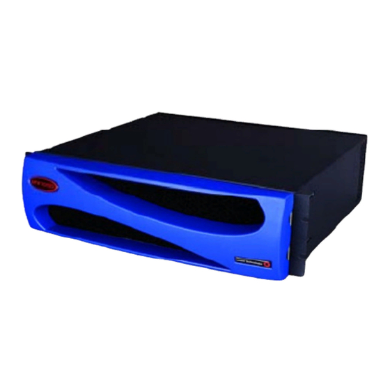
Page 18: Figure 1-1 Apx 1000 Chassis, Front View
• Dual ac or dc power supplies Slot cards in an APX 1000 unit connect to each other via the backplane. The shelf controller manages the system and interacts with the slot cards. Figure 1-2. APX 1000 chassis, rear view... -
Page 19: Apx 1000 Shelf
Note: Although it is physically possible to place slot cards from other members of the APX product line in the APX 1000, they are not supported for use in the APX 1000. Only slot cards sold with the APX 1000 as part of the following configurations are supported. - Page 20 Caution: Wear an antistatic wrist strap before handling any of the unit components. This strap should be connected to ground potential. For information about installing a slot card in a slot, see Chapter 3, “Installing an APX 1000 Chassis.” APX 1000™ Getting Started Guide...
-
Page 21: Apx 1000 Slot Cards For Other Configurations
APX 1000 system overview APX 1000 slot cards for other configurations Table 1-3 lists other slot cards that you can use in an APX 1000 unit for additional configurations to meet local needs. For detailed slot card descriptions, see Appendix B, “Slot Card Specifications.”... -
Page 23: Preparing For Installation
Understanding APX 1000 slot cards ........ -
Page 24: Checking The Package Contents
A blank power supply filler card, if the unit is equipped with only a single power supply. Checking the package contents APX 1000 package contents vary, depending on the configuration of the unit you order. After opening the package, verify that you have all the system components that were ordered. -
Page 25: Selecting The Installation Site
Preparing for Installation Selecting the installation site Selecting the installation site Before you choose a setup location for a APX 1000 unit, read and follow the site and electrical requirements defined in Appendix D, “Safety-Related Electrical, Physical, and Environmental Information.”... -
Page 26: Understanding The Shelf Controller Back Panel
Preparing for Installation Understanding the shelf controller back panel Table 2-1 details the intended use of each slot in the back panel of the APX 1000 chassis. Table 2-1. APX 1000 slot usage Slot ID Intended usage Supported slot cards... -
Page 27: Shelf Controller Status Lights
Shelf controller status lights The status lights on the APX 1000 shelf controller can help you identify a problem, especially if it occurs shortly after you turn the power on. Figure 2-4 shows the location of the status lights on the shelf controller slot card, and Table 2-3 explains what the lights indicate. -
Page 28: Understanding Power Supplies
The APX 1000 unit can be equipped with two hot-swappable ac or dc power supplies. One power supply is sufficient to provide power to the unit. When an APX 1000 unit is equipped with two power supplies, they share the power load of the unit equally and act as a redundant backup for each other if one supply fails. -
Page 29: Dc Power Supplies
The power supply does not sense any internal voltage. dc power supplies Caution: Be sure that the power switch on the APX 1000 dc power supply is in the off position when you are connecting the supply to a local dc power source. -
Page 30: Ingress Slot Cards
Ingress cards support digital line connections (usually channelized) for incoming connections to the APX 1000. These cards are designed to occupy slot number 5, except for the narrow width 8-port E1 card, which can be installed in slots 1 to 4. -
Page 31: Installing An Apx 1000 Chassis
Connecting the APX 1000 ac power supply ....... . 3-10... -
Page 32: Handling Apx 1000 Components
• The unit’s fans draw air in from the front and exhausts it in the rear to sufficiently cool each unit. Consequently, air gaps at the top, bottom, or sides of APX 1000 units are not required. Handling APX 1000 components To prevent damage to components from electrostatic discharge, always follow the proper guidelines for equipment handling and storage. -
Page 33: Figure 3-1 Wrist Grounding Strap
Installing an APX 1000 Chassis Handling APX 1000 components Figure 3-1. Wrist grounding strap To minimize entanglement, right-handed people can wear the strap on the left hand. Plug the other end of the wrist strap into the grounding jack provided on most Lucent products, as shown in Figure 3-2. -
Page 34: Remove Plastics From Your Work Area
Figure 3-3. APX 1000 dimensions 18.5 in. 5.2 in. 17.2 in. The APX 1000 can be mounted in a 19-inch rack (48.26cm), or in a 23-inch (58.42cm) rack, using the dual-purpose mounting adapters that are included with the unit. APX 1000™ Getting Started Guide... -
Page 35: Mounting Adapters
Figure 3-4. APX 1000 dual-purpose mounting adapter When the APX 1000 unit is mounted in a 19-inch rack, you must turn each adapter so that its narrow tab faces toward the front of the unit. Then use four of the screws that are provided to attach the wide tab of each adapter to the sides of the unit. -
Page 36: Mounting In A 19-Inch Rack
Figure 3-6. Align the holes in the mounting adapters with the screw holes in the chassis and attach the mounting adapters to the APX 1000 chassis, as shown in Figure 3-6, with the screws that are provided. -
Page 37: Mounting In A 23-Inch Rack
Figure 3-7. Align the holes in the mounting adapters with the screw holes in the chassis and attach the mounting adapters to the APX 1000 chassis, as shown in Figure 3-7, with the screws that are provided. -
Page 38: Installing Or Replacing Apx 1000 Power Supplies
Installing an APX 1000 Chassis Installing or replacing APX 1000 power supplies Figure 3-7. APX 1000 installation in a 23 inch rack (front mounting position shown) Replace all slot cards and power supplies in the same slot locations from which they were removed. -
Page 39: Figure 3-9 Apx 1000 Power Supply Slot, Guide Tab, And Track
Installing or replacing APX 1000 power supplies The APX 1000 power supply is secured by a single locking screw on the right side of the power supply module. Use the following procedure to remove and replace an APX 1000 power supply: Turn off the power supply and safely disconnect it from its power source. -
Page 40: Connecting The Apx 1000 Ac Power Supply
) wire to connect the chassis ground to the facility’s ground. If the APX 1000 unit is fed from an isolated power supply, you must supply a solid ground to earth via copper rods. This ground must have a resistance of less than 5 ohms. -
Page 41: Connecting The Apx 1000 Dc Power Supply
Use terminal lug part number PV12-6HDR-L or equivalent Replace the lexan cover over the terminal screws A single drop to all APX 1000 units on one rack is acceptable. Figure 3-11 shows an example of wiring the dc terminal block. -
Page 42: Connecting A Workstation To The Apx 1000 Serial Port
Connecting a workstation to the APX 1000 serial port Connecting a workstation to the APX 1000 serial port To perform the initial configuration of the APX 1000 unit, you must connect a workstation to the unit’s serial port. Connect a serial cable from your workstation to the unit as shown in Figure 3-12. -
Page 43: Checking For The Presence Of The Pcmcia Card
Make sure a PCMCIA card is inserted in the top PCMCIA slot as shown in Figure 3-14. A PCMCIA card can also be placed in the lower slot. However, the APX 1000 unit uses information from the card in the top slot by default when booting. -
Page 44: Powering Up An Apx 1000 Unit
Some slot cards from the larger APX family of products are not appropriate for installation in an APX 1000 unit. If you are installing a slot card that was not shipped with the APX 1000, make sure that it is appropriate for installation in this unit, and that the software running on the APX 1000 supports the card. -
Page 45: Installing An Apx 1000 Slot Card
Installing or replacing APX 1000 slot cards You must also verify that your system software supports any newly released APX 1000 slot card that you want to install on your unit. If the card is not supported by your current system software, you must upgrade your system software before installing the card. -
Page 46: Figure 3-16 Rear Connector Examination
Installing an APX 1000 Chassis Installing or replacing APX 1000 slot cards Figure 3-16. Rear connector examination Hold the slot card so that the panel is facing you and the lock screw is on the left, and insert the card into the open slot as shown in Figure 3-17. -
Page 47: Removing Slot Cards
Return to the jack screw on the right side of the panel and finish tightening the screw. Removing slot cards To remove slot cards from the APX 1000 chassis proceed as follows: Using a number 2 Phillips screwdriver, completely loosen the lock screw (on the left side of the card, as shown in Figure 3-19). -
Page 48: Replacing Apx 1000 Fans And Filters
To replace the fan assembly of an APX 1000 unit, use the following procedure: Remove the front cover of the APX 1000. To do so, place two fingers of each hand into the notches on each side of the plastic panel, shown in Figure 3-20, and pull. -
Page 49: Air Filter Replacement
(lower holes obscured) Air filter replacement The air filter mounts on the front of the fan assembly, and can be replaced while the APX 1000 is in service without affecting the operation of the unit. The air filter should be checked every six months and replaced, if needed. -
Page 50: Figure 3-23 Apx 1000 Air Filter And Filter Holder
Replacing APX 1000 fans and filters Remove the front cover of the APX 1000. To do so, place two fingers of each hand into the notches on each side of the plastic panel, as shown in Figure 3-20, and pull. -
Page 51: Figure 3-25 Filter Mounting Tabs And Slots
Installing an APX 1000 Chassis Replacing APX 1000 fans and filters Figure 3-25. Filter mounting tabs and slots Mounting tabs Secure the filter holder in place by replacing the filter retaining screw, removed in step 2. Replace the front cover as shown in Figure 3-22. -
Page 53: Overview Of Apx 1000 Operation And Configuration
APX 1000 configuration overview........ -
Page 54: Shelf Controller Configuration
IP address, you can telnet into the unit from a local host and download configuration files from a TFTP server to the APX 1000 system. An APX 1000 unit has a range of options for configuring this IP interface and for protecting the unit from unauthorized administrative access. -
Page 55: Onboard Flash Memory And Software Updates
Administration Guide. RADIUS support You can use RADIUS to store user profiles for connections that terminate on the APX 1000. The RADIUS server must be compliant with vendor-specific attributes (VSAs), as defined in RFC 2138. To use RADIUS, you must also configure the APX 1000 unit to communicate with the RADIUS server. -
Page 56: Verifying Slot Card Operation
APX 1000 configuration, see the APX 8000/MAX TNT Administration Guide. Verifying slot card operation You can verify which slot cards are present and operational in an APX 1000 unit by entering the show command as demonstrated in the following example: admin>... -
Page 57: Configuring The Shelf Controller
Once the APX 1000 has been configured with an IP address, it can be reached on the IP network via a Telnet connection. The following information provides details of these connection methods. -
Page 58: Network Connection To A Workstation Console
Figure 5-1. Serial management connection to the APX 1000 To connect the console terminal to the APX 1000 unit, connect one end of a shielded crossover cable to the serial port (CONTROL) on the shelf controller. Then connect the other end of the shielded crossover cable to the serial port on the console device. -
Page 59: Connecting A Dial-In Backup Management Connection
To configure a backup administrative connection with an external modem, connect the modem to the APX 1000 serial (CONTROL) port via a null modem (crossover) cable. In addition, you might need a DB-25-to-DB-9 adapter. Figure 5-3 shows the backup administrative connection via a modem to the APX 1000 unit. -
Page 60: Logging Into The Shelf Controller
Logging into the shelf controller Figure 5-3. Backup administrative connection via a modem to the APX 1000 unit The modem you use to connect to the APX 1000 must be configured as follows: • Dumb mode. Dumb mode causes the modem to ignore data on the receive data (RD) lead. -
Page 61: Restricting Administrative Access
For details about User profiles, see the APX 8000/MAX TNT Administration Guide. Restricting administrative access Each APX 1000 unit is shipped from the factory with its security features set to defaults that allow you to easily access the unit so you can configure it without any restrictions. Before you bring the unit online, you must change the default security settings to protect the configured unit from unauthorized access. -
Page 62: Setting A Telnet Password
USER/admin written When you telnet into the APX 1000 unit, the system prompts for the name and password of a User profile and authenticates the information before allowing the Telnet session. The following example shows the use of the password that was set previously. When entered during an actual Telnet session, this password will not be displayed on screen. -
Page 63: Providing A Basic System Ip Configuration
To enable Telnet and SNMP access to the unit, and to allow connectivity between the unit and local IP hosts, you must assign an IP address to the APX 1000 Ethernet port on the shelf controller and configure basic IP routing. -
Page 64: Netmasks
If no subnet mask is specified for a class C address, the APX 1000 unit uses the default mask of 24 bits, as shown in Figure 5-4. Figure 5-4. Default netmask for class C IP address... -
Page 65: Table 5-2 Decimal Subnet Masks And Prefix Lengths
The broadcast address of any subnet has the host portion of the IP address set to all 1s (ones). The network address (or base address) represents the network itself, because the host portion of the IP address is all 0s (zeros). For example, supposing that the APX 1000 configuration assigns the following address to a remote router: 198.5.248.120/29... -
Page 66: Assigning The Ethernet Ip Addresses
Ethernet addresses for carrying user traffic. After you assign IP addresses, you can verify that the APX 1000 unit is a valid IP host on its configured network by pinging other network hosts, as shown in the following example: admin>... -
Page 67: Verifying An Administrative Lan Connection
APX 1000 unit via its IP address. You can test this connectivity by pinging the unit from the local host. For example, the following command entered on a local host tests connectivity to the APX 1000 address, configured previously: % ping 1.1.1.1... -
Page 68: Overview Of Configuration To Provide Service
These settings are available from the service provider of the line, and must be set properly for the APX 1000 unit to communicate with the device at the far end of the line. Obtain the line parameters from the service provider, and then configure the ingress line card(s) in your unit, using the relevant information for that card contained in the APX 1000 Physical Interface Configuration Guide. -
Page 69: Digital Line Interfaces
Digital line interfaces Depending on the slot card that is installed, digital lines can connect the APX 1000 unit to switches within the local telephone network, supporting dial-in connections from users. Or the lines can connect the unit to an ATM switch, supporting permanent virtual circuit (PVC) user connections. -
Page 70: Network Interfaces
ISDN, or robbed-bit signaling modes. Network interfaces The APX 1000 unit extracts voice or data information from the digital line and encapsulates it as IP data for routing onto a network. Network connections are supported by the following slot cards described in the following sections. -
Page 71: Shelf Controller Interfaces
No parity – 1 stop bit – No flow control • An RJ-45 connector for a 10/100BaseT Ethernet connection. • A PCMCIA interface, designed to accept PCMCIA flash-memory cards. Other PCMCIA devices are not supported. APX 1000™ Getting Started Guide... -
Page 73: Table B-1 Fault Indicator States During Slot Card Operations
SWAN2 slot card ........... . . B-18 Multipurpose status indicator on slot cards APX 1000 slot cards have a multipurpose FAULT status indicator light at the right side of the front panel. Table B-1 describes the states of the multipurpose indicator during slot card operations. -
Page 74: Appendix B Slot Card Specifications
288 ports of supported application per 288-port MultiDSP card Power requirements 37 watts, 7.4 amps for the 96-port MultiDSP card 48 watts, 9.6 amps for the 288-port MultiDSP card Card weight Approximately 1.5 pounds (0.7kg) Hot swap capability APX 1000™ Getting Started Guide... -
Page 75: Hybrid Access Iii Slot Card
DS2 groups, each of which includes four DS1 lines, each of which in turn is composed of 24 DS0 channels, for a total of 672 DS0 channels. Note: Because of its dimensions, this card can be installed only in the APX 1000 top slot (slot 5). -
Page 76: 24-Port T1 Or E1 Slot Card
The 24-port T1 or E1 slot card (APX1-SL-24CT1CE1), shown in Figure B-4, provides separate interfaces for 24 individual T1 or E1 lines. The ability of the card to support either T1 or E1 service is determined by application of the appropriate hash code. APX 1000™ Getting Started Guide... -
Page 77: Status Indicator
Slot Card Specifications 24-port T1 or E1 slot card Figure B-4. 24-port T1 or E1 slot card Note: Because of its dimensions, this card can be installed only in the APX 1000 top slot (slot 5). Status indicator The 24-port T1 or E1 card provides the FAULT indicator described in “Multipurpose status indicator on slot cards”... -
Page 78: Table B-6 E1 Specifications For The 24-Port T1 Or E1 Slot Card
ANSI T1.403 and Telecordia (BELLCORE) TA-TSY-000191. Connectors 24 100-ohm RJ-45 Card dimensions 15.1 inches wide by 10.7 inches long (38.354cm x 27.178cm): To be installed only in the APX 1000 top slot Card weight ~2 pounds (0.9kg) Operating humidity 0-90%, noncondensing Operating temperature 32-122°... -
Page 79: 8-Port T1 Slot Card
8 individual T1 lines. This card supports a low density T1 configuration of the APX 1000. It is available only as a wide format card, designed to be installed in slot 5 of the APX 1000. Figure B-5. 8-port T1 slot card front panel Status indicator The 8-port T1 card provides the FAULT indicator described in “Multipurpose status indicator... -
Page 80: 8-Port E1 Slot Card
APX 1000 slots. Each version provides 8 E1 interfaces. They can be used together to equip the APX 1000 with a total of 16 E1 interfaces. Each E1 interface supports 30 64Kbps DS0 channels, each of which can transmit and receive data or digitized voice. -
Page 81: Ethernet-3Nd Slot Card
Operating humidity 0-90%, noncondensing Operating temperature 32-122° F (0-50° C) Ethernet-3ND slot card The Ethernet-3ND (no dongle) slot cards for the APX 1000 (APX1-SL-E100) have four full-duplex 10/100-megabit (Mb) Ethernet ports and have high packet-per-second throughput APX 1000™ Getting Started Guide... -
Page 82: Ethernet-3Nd Status Indicators
Must meet Japanese Industrial Standards (JIS) C 5973. Card dimensions 5.6 inches high by 10.7 inches long (14.2cm x 27cm) Card weight ~2 pounds (0.9kg) Operating humidity 0-90%, noncondensing Operating temperature 32-122° F (0-50° C) B-10 APX 1000™ Getting Started Guide... -
Page 83: Ethernet-3 Slot Card
Must meet Japanese Industrial Standards (JIS) C 5973. Card dimensions 5.6 inches high x 10.7 inches long (14.2cm x 27cm) Card weight ~2 pounds (0.9kg) Operating humidity 0 to 90%, noncondensing Operating temperature 32-122° F (0-50° C) APX 1000™ Getting Started Guide B-11... -
Page 84: Apx Ethernet Card
APX Ethernet card APX Ethernet card The APX Eternet slot card (APX-SL-E100) is an optional egress card for the APX 1000. It has two full-duplex 10/100Mbps Ethernet ports with a high throughput to support VoIP. An APX Ethernet card supports autonegotiation, a process in which Ethernet devices exchange information and agree on a communication mode (for example, 10Mbps or 100Mbps, full or half duplex). -
Page 85: Specifications
Operating temperature 32-122° F (0-50° C) DS3-ATM2 card The DS3-ATM2 slot card (APX8-SL-UDS3A2-C) enables an APX 1000 unit to provide one active and one standby trunk connection at data rates of 44.736Mbps. DS3-ATM2 status indicators In addition to the indicator described in “Multipurpose status indicator on slot cards” on page B-1, the DS3-ATM2 card provides the status indicators shown in Figure B-11. -
Page 86: Ds3-Atm2 Technical Specifications
On a DS3 Red alarm, a Yellow signal is sent on the DS3 line and an Alarm Indication signal (AIS) is sent on DS2 lines. On a DS2 Red alarm, an AIS is sent on DS1 lines. Connectors 75-ohm BNC coaxial B-14 APX 1000™ Getting Started Guide... -
Page 87: Oc3-Atm2 Card
ON indicates the OC3 interface is enabled and has not detected any error conditions. ON indicates the OC3 interface is out of frame alignment. ON indicates the OC3 interface is experiencing a loss of the receive signal. APX 1000™ Getting Started Guide B-15... -
Page 88: Table B-18 Oc3-Atm2 Copper Card Specifications
2 pounds (0.9 kilograms) Operating humidity 0-90 percent, noncondensing Operating 32-122° F (0-50° C) temperature Table B-19 describes OC3-ATM2 Short-Haul card specifications. Table B-19. OC3-ATM2 Short-Haul card specifications Category Specification Power requirements 35 W B-16 APX 1000™ Getting Started Guide... -
Page 89: Table B-20 Oc3-Atm2 Long-Haul Card Specifications
Table B-20. OC3-ATM2 Long-Haul card specifications Category Specification Power requirements 35 W Connectors Fiber SC-1 Interfaces per card One full-duplex OC-3c/STM-1 SONET/SDH Cable requirements Single mode (SM) cables: 9/125-micron optical fiber Connector Must meet JIS C 5973 standards requirements APX 1000™ Getting Started Guide B-17... -
Page 90: Swan2 Slot Card
The indicator light on the left of the 120-pin connector is amber when the serial daughter board is starting up or restarting, green when at least one of the four serial ports is operating, and off otherwise. B-18 APX 1000™ Getting Started Guide... -
Page 91: Table B-21 Swan Card Specifications
Must meet Japanese Industrial Standards (JIS) C 5973 Card dimensions 8.8 inches wide by 10.6 inches long (22.35cm x 26.92cm) Card weight 3.9 pounds (1.77kg) Operating humidity 0% to 90% noncondensing Operating temperature 32 to 104° F (0 to 40° C) APX 1000™ Getting Started Guide B-19... -
Page 93: Appendix C Cabling And Connector Specifications
Serial port specifications The APX 1000 serial (CONTROL) port uses a standard DB-9 female connector that conforms to the EIA RS-232 standard for serial interfaces. The APX 1000 uses the RS-232 pinouts listed in Table C-1. Table C-1. Serial port and cable pinouts... -
Page 94: Ethernet Interface Specifications
You configure these parameters during installation. (For more information, see the APX 8000™/MAX TNT® Reference.) Once you install the APX 1000 unit, you must notify the carrier before disconnecting the unit from the WAN. If you disconnect or turn off the unit without prior notification, the carrier might temporarily discontinue your T1/PRI service. -
Page 95: T1/Pri Cable Specifications
The maximum cable distance between the T1/PRI WAN interface equipment and an APX 1000 unit without CSUs should not exceed 655 feet (200m). Measure the line length and record it when you install the APX 1000 unit. You must specify this length when you configure the parameters in the line’s profile. -
Page 96: T1/Pri Crossover Cable: Rj-48C To Rj-48C
(at the APX 1000) (APX 1000) (remote WAN) Receive Transmit Figure C-1. RJ-48C to RJ-48C crossover cable RECEIVE 1 RECEIVE 2 5 TRANSMIT TRANSMIT 4 4 TRANSMIT TRANSMIT 5 2 RECEIVE 1 RECEIVE Male RJ-48C Male RJ-48C APX 1000™ Getting Started Guide... -
Page 97: T1/Pri Straight-Through Cable: Rj-48C To Rj-48C
(at the APX 1000) (APX 1000) (remote WAN) Receive Transmit Figure C-2. RJ-48C to RJ-48C straight-through cable RECEIVE 1 RECEIVE 2 5 TRANSMIT TRANSMIT 4 4 TRANSMIT TRANSMIT 5 2 RECEIVE 1 RECEIVE Male RJ-48C Male RJ-48C APX 1000™ Getting Started Guide... -
Page 98: T1/Pri Straight-Through Cable: Rj-48C To
Before installing the RJ-48C to DB-15 straight-through cable, verify that the WAN transmits the signal received by the APX 1000 on pins 3 and 11 and receives the signal transmitted by the APX 1000 on pins 1 and 9. Table C-5 and Figure C-3 show the pinouts. -
Page 99: T1/Pri Crossover Cable: Rj-48C To
(APX 1000) (remote WAN) Receive Transmit Figure C-4. RJ-48C to DB-15 crossover cable Male RJ-48C 5 TRANSMIT 4 TRANSMIT 2 RECEIVE 11 TRANSMIT TRANSMIT 3 1 RECEIVE 9 RECEIVE RECEIVE 1 Male DB-15 Male RJ-48C APX 1000™ Getting Started Guide... -
Page 100: T1/Pri Straight-Through Cable: Rj-48C To Bantam
Tip 2 Ring 2 Figure C-5. RJ-48C to Bantam straight-through cable TIP 1 RECEIVE RING 1 RECEIVE 5 TRANSMIT 4 TRANSMIT RING 2 TRANSMIT 2 RECEIVE TIP 2 TRANSMIT 1 RECEIVE Male Dual 310-P Male RJ-48C APX 1000™ Getting Started Guide... -
Page 101: T1 Rj-48C-Loopback Plug
MultiRate and GloBanD primary rate interface (PRI) network services, and global virtual private network services (GVPN). Note: APX 1000 units can only access Switched 56Kbps services on a T1 access line or a Switched-56 line. For a listing of the compatible switch types, see the Switch-Type parameter listing in the APX 8000™/MAX TNT®... -
Page 102: E1/Pri Interface Specifications
E1/PRI interface specifications APX 1000 E1/PRI specifications apply to cables and WAN ports. E1/PRI cable specifications The WAN interface cables and plugs described in this section are available for the APX 1000 unit’s WAN interfaces. E1/PRI crossover cable: RJ-48C to RJ-48C Before installing the RJ-48C to RJ-48C crossover cable, verify that the WAN interface transmits on pins 5 and 4 and receives on pins 2 and 1. -
Page 103: E1/Pri Straight-Through Cable: Rj-48C To Rj-48C
2 and 1 and receives on pins 5 and 4. Table C-11 and Figure C-7 show the pinouts. Table C-11.RJ-48C to RJ-48C straight-through cable specifications Pair Signal Male RJ-48C Male RJ-48C (at the APX 1000) (APX 1000) (remote WAN) Receive Transmit Figure C-7. RJ-48C to RJ-48C straight-through cable APX 1000™ Getting Started Guide C-11... -
Page 104: E1/Pri Straight-Through Cable: Rj-48C To
3 and 11 and receives on pins 1 and 9. Figure C-8 and Table C-12 show the pinouts. Table C-12.RJ-48C to DA-15 straight-through cable specifications Pair Signal Male RJ-48C Male DA-15 (at the APX 1000) (APX 1000) (remote WAN) Receive Transmit Figure C-8. RJ-48C to DA-15 straight-through cable C-12 APX 1000™ Getting Started Guide... -
Page 105: E1/Pri Crossover Cable: Rj-48C To Da
9 and receives on pins 3 and 11. Figure C-9 and Table C-13 show the pinouts. Table C-13.RJ-48C to DA crossover cable specifications Pair Signal Male RJ-48C Male DA-15 (at the APX 1000) (APX 1000) (remote WAN) Receive Transmit Figure C-9. RJ-48C to DA crossover cable APX 1000™ Getting Started Guide C-13... -
Page 106: E1/Pri Straight-Through Cable: Rj-48C To Bantam
Table C-14.RJ-48C to Bantam straight-through cable specifications Pair Signal Male RJ-48 Male Dual 310-P (at the APX 1000) (APX 1000) Bantam (remote WAN) Receive Tip 1 Ring 1 Transmit Tip 2 Ring 2 Figure C-10. RJ-48C to Bantam straight-through cable C-14 APX 1000™ Getting Started Guide... -
Page 107: E1/Pri Wan Connector Pins
E1/PRI interface specifications E1/PRI WAN connector pins Table C-15 lists the pins on RJ-48C sockets used for an E1/PRI WAN interface on APX 1000 units. Only pins 1, 2, 4, and 5 are used. The remaining pins are not connected. -
Page 109: Appendix D Safety-Related Electrical, Physical, And Environmental Information
Electronic and electrical specifications Battery The APX 1000 shelf controller contains an internal 3V lithium battery. The normal operating life of this battery exceeds five years. Make sure that only trained engineers authorized by Lucent Technologies open the APX 1000 shelf controller for testing, maintenance, installation, or any other purpose. -
Page 110: Electrical Requirements
Electrical requirements The APX 1000 can be powered from a dc or ac power source, or both. The power source is wired to the power supplies on the right side at the rear of the chassis. Although a single ac or dc power supply is sufficient to operate the unit, it can be equipped with two power supplies of either type, or one power supply of each type in combination. -
Page 111: Governmental Notices
Notice, FCC Part 68 Notice), Canada, the European Union, Australia and New Zealand, and Japan, can be found in the Edge Access Safety and Compliance Guide. EMI class APX 1000 units are Class A electronic equipment and are likely to cause harmful electromagnetic interference (EMI) to radio communications when operated in residential areas. -
Page 112: Environmental Specifications
40 pounds (18.2kg) maximum (fully configured) Environmental specifications For best results, install the APX 1000 unit in an environment with constant temperature and humidity. In general, cooler environments are better. Humidity must be high enough to prevent accumulation of static electricity, but low enough to prevent condensation. -
Page 113: Index
3-11 checking flash card after 3-14 default route, IP 5-10 DIAG PORT. See serial port DS3-ATM2 card specifications B-13 cables T1/PRI bantam T1/PRI crossover, RJ-48C/RJ-48C T1/PRI RJ-48C/DB-15 crossover T1/PRI specifications E1 card, specifications APX 1000 Getting Started Guide Index-1... - Page 114 Hybrid Access how the unit uses it nailed channels, HDLC resources netmask installation connecting to the LAN 3-12 OC3-ATM2 card installing the APX 1000 chassis status lights B-15 overview preparing for online help, commands Index-2 APX 1000 Getting Started Guide...
- Page 115 LAN 3-12 described reading lights T1 card, specifications size of chassis T1 RJ48C-Loopback plug slot cards APX Ethernet B-12 T1/PRI DS3-ATM2 B-13 cable specifications interface specifications Ethernet-3 B-11 WAN connection specifications APX 1000 Getting Started Guide Index-3...
- Page 116 TFTP, downloading files User profile USOC jacks and codes vendor-specific attribute (VSA) requirements, RADIUS WAN (Wide Area Network) ports E1/PRI connector specifications C-15 WAN interfaces supported weight of unit workstation, connecting Index-4 APX 1000 Getting Started Guide...
Need help?
Do you have a question about the APX 1000 and is the answer not in the manual?
Questions and answers