Sign In
Upload
Manuals
Brands
Lucent Technologies Manuals
Gateway
APX 1000
Lucent Technologies APX 1000 Manuals
Manuals and User Guides for Lucent Technologies APX 1000. We have
2
Lucent Technologies APX 1000 manuals available for free PDF download: Getting Started Manual, Specifications
Lucent Technologies APX 1000 Getting Started Manual (116 pages)
Brand:
Lucent Technologies
| Category:
Gateway
| Size: 2 MB
Table of Contents
Customer Service
3
Table of Contents
5
About this Guide
13
What Is in this Guide
13
What You Should Know
13
Documentation Conventions
14
Documentation Set
15
Chapter 1 Overview of APX 1000 System and Features
17
APX 1000 Features Overview
17
APX 1000 System Overview
17
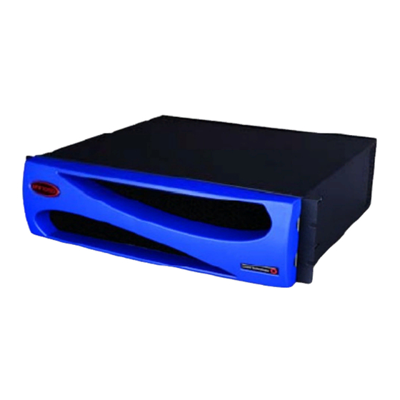
Figure 1-1 APX 1000 Chassis, Front View
18
Figure 1-2 APX 1000 Chassis, Rear View
18
APX 1000 Shelf
19
APX 1000 Slot Cards for Primary Configurations
19
Table 1-1 APX 1000 Primary Configurations and Slot Cards
19
Table 1-2 APX 1000 Slot Cards for Primary Configurations
19
APX 1000 Slot Cards for Other Configurations
21
Table 1-3 APX 1000 Slot Cards for Other Configurations
21
Chapter 2 Preparing for Installation
23
Before You Begin
23
Checking the Package Contents
24
Figure 2-1 APX 1000 Shelf
24
Selecting the Installation Site
25
Required Installation Tools and Equipment
25
Understanding the Unit's Back Panel
25
Figure 2-2 Back Panel of the APX 1000
25
Understanding the Shelf Controller Back Panel
26
Shelf Controller Connectors and Slots
26
Table 2-1 APX 1000 Slot Usage
26
Shelf Controller Status Lights
27
Figure 2-3 APX 1000 Shelf Controller Back Panel
27
Figure 2-4 APX 1000 Status Lights
27
Table 2-2 Shelf Controller Back-Panel Elements
27
Table 2-3 APX 1000 Status Light Indications
27
Understanding Power Supplies
28
Ac Power Supplies
28
Figure 2-5 APX 1000 Ac Power Supply
28
Table 2-4 APX 1000 Power Supply Status Lights
28
DC Power Supplies
29
Understanding APX 1000 Slot Cards
29
Figure 2-6 APX 1000 DC Power Supply
29
DSP Slot Cards
30
Egress Slot Cards
30
Ingress Slot Cards
30
Chapter 3 Installing an APX 1000 Chassis
31
Temperature Guidelines for Installing Units in a Rack or Cabinet
31
Handling APX 1000 Components
32
Use a Wrist Strap
32
Figure 3-1 Wrist Grounding Strap
33
Figure 3-2 Plugging the Wrist Strap into a Grounding Jack
33
Remove Plastics from Your Work Area
34
Store Components Properly
34
Mounting an APX 1000 Unit
34
Figure 3-3 APX 1000 Dimensions
34
Chassis Mounting Points
35
Figure 3-4 APX 1000 Dual-Purpose Mounting Adapter
35
Mounting Adapters
35
Figure 3-5 APX 1000 Chassis Mounting
36
Mounting in a 19-Inch Rack
36
Figure 3-6 APX 1000 Installation in a 19-Inch Rack (Rear Mounting Position Shown)
37
Mounting in a 23-Inch Rack
37
Installing or Replacing APX 1000 Power Supplies
38
Figure 3-7 APX 1000 Installation in a 23 Inch Rack (Front Mounting Position Shown)
38
Figure 3-8 APX 1000 Blank Power Supply Module
38
Figure 3-9 APX 1000 Power Supply Slot, Guide Tab, and Track
39
Connecting the APX 1000 Ac Power Supply
40
Figure 3-10 Installing the Power Supply
40
Connecting the APX 1000 DC Power Supply
41
Figure 3-11 Connecting to DC Power
41
Connecting a Workstation to the APX 1000 Serial Port
42
Connecting an APX 1000 Unit to a LAN
42
Figure 3-12 Connecting a Serial Cable to an APX 1000 Unit
42
Checking for the Presence of the PCMCIA Card
43
Figure 3-13 Connecting an Ethernet Cable
43
Powering up an APX 1000 Unit
44
Installing or Replacing APX 1000 Slot Cards
44
Installing an APX 1000 Slot Card
45
Figure 3-15 Wrist Strap Grounding
45
Figure 3-16 Rear Connector Examination
46
Figure 3-17 Inserting a Slot Card
46
Removing Slot Cards
47
Figure 3-18 Tightening the Jack Screw
47
Figure 3-19 Tightening the Lock Screw
47
Replacing APX 1000 Fans and Filters
48
Fan Replacement
48
Figure 3-20 Front Cover Notches
48
Air Filter Replacement
49
Figure 3-21 Removing the Fan Assembly (Shown Without a Filter)
49
Figure 3-22 Front Cover Mounting Pins and Holes
49
Figure 3-23 APX 1000 Air Filter and Filter Holder
50
Figure 3-24 Removal of Filter Material
50
Figure 3-25 Filter Mounting Tabs and Slots
51
Chapter 4 Overview of APX 1000 Operation and Configuration
53
APX 1000 Operation
53
APX 1000 Configuration Overview
53
Figure 4-1 Example of APX 1000 Voice/Data Access Server Operations
53
Shelf Controller Configuration
54
APX 1000 Management Features
54
Using the Command-Line Interface
54
Onboard Flash Memory and Software Updates
55
RADIUS Support
55
Tracking System Activity
55
Verifying Slot Card Operation
56
Chapter 5 Configuring the Shelf Controller
57
Shelf Controller Configuration Overview
57
Administrative Connections
57
Serial Connection to a Console
57
Network Connection to a Workstation Console
58
Figure 5-1 Serial Management Connection to the APX 1000
58
Administrative Connections
58
Connecting a Dial-In Backup Management Connection
59
Figure 5-2 Ethernet Connection to a Workstation
59
Logging into the Shelf Controller
60
Figure 5-3 Backup Administrative Connection Via a Modem to the APX 1000 Unit
60
Restricting Administrative Access
61
Changing Defaults for Serial-Port Logins
61
Changing the Default Admin Password
61
Setting a Telnet Password
62
Providing a Basic System IP Configuration
63
IP Address Syntax
63
Netmasks
64
Subnets
64
Figure 5-4 Default Netmask for Class C IP Address
64
Table 5-1 IP Address Classes and Number of Network Bits
64
Table 5-2 Decimal Subnet Masks and Prefix Lengths
65
Assigning the Ethernet IP Addresses
66
Configuring a Default Route
66
Verifying an Administrative LAN Connection
67
Figure 5-5 Local Router to be Used as Default Route
67
Overview of Configuration to Provide Service
68
Ingress Line Configuration
68
Modem Configuration
68
Egress Configuration
68
Appendix A APX 1000 Intended Use
69
Digital Line Interfaces
69
Network Interfaces
70
LAN Interface
70
WAN Interfaces
70
Shelf Controller Interfaces
71
Table B-1 FAULT Indicator States During Slot Card Operations
73
Appendix B Slot Card Specifications
74
Multidsp Slot Cards
74
Multidsp Status Indicator
74
Multidsp Technical Specifications
74
Figure B-1 Multidsp Cards
74
Multipurpose Status Indicator on Slot Cards
74
Table B-2 Multidsp Slot Card Specifications
74
Channelized T3 Slot Card
75
Figure B-2 HDLC2 Card
75
Hybrid Access III Slot Card
75
24-Port T1 or E1 Slot Card
76
Table B-3 T3 Slot Card Status Indicators
76
Table B-4 T3 Slot Card Specifications
76
Status Indicator
77
T1 Technical Specifications
77
Table B-5 T1 Specifications for the 24-Port T1 or E1 Slot Card
77
Table B-6 E1 Specifications for the 24-Port T1 or E1 Slot Card
78
8-Port T1 Slot Card
79
Status Indicator
79
T1 Technical Specifications
79
Table B-7 T1 Specifications for the 8-Port T1 Slot Card
79
8-Port E1 Slot Card
80
E1 Status Indicators
80
Ethernet-3ND Slot Card
81
Table B-8 8-Port E1 Slot Card Specifications
81
Ethernet-3ND Status Indicators
82
Ethernet-3ND Technical Specifications
82
Figure B-8 Ethernet-3ND Slot Card Front Panel
82
Table B-10 Ethernet-3ND Slot Card Specifications
82
Table B-9 Ethernet-3ND Status Indicators
82
Ethernet-3 Slot Card
83
Status Indicators
83
Specifications
83
Figure B-9 Ethernet 3 Slot Card
83
Table B-11 Ethernet-3 Slot Card Status Indicators
83
Table B-12 Ethernet-3 Card Specifications
83
APX Ethernet Card
84
Status Indicators
84
Figure B-10 APX Ethernet Slot Card
84
Table B-13 APX Ethernet Status Lights
84
Specifications
85
DS3-ATM2 Card
85
DS3-ATM2 Status Indicators
85
Figure B-11 DS3-ATM2 Card Front Panel
85
Table B-14 APX Ethernet Slot Card Specifications
85
Table B-15 DS3-ATM2 Card Status Indicators
85
DS3-ATM2 Technical Specifications
86
Table B-16 DS3-ATM2 Card Specifications
86
OC3-ATM2 Card
87
Table B-17 OC3-ATM2 Status Lights
87
Table B-18 OC3-ATM2 Copper Card Specifications
88
Table B-19 OC3-ATM2 Short-Haul Card Specifications
88
Table B-20 OC3-ATM2 Long-Haul Card Specifications
89
SWAN2 Slot Card
90
Table B-21 SWAN Card Specifications
91
Appendix C Cabling and Connector Specifications
93
Serial Port Specifications
93
Table C-1 Serial Port and Cable Pinouts
93
Ethernet Interface Specifications
94
Supported Ethernet Types
94
Required Equipment for 10Baset or 100Baset
94
T1/PRI Interface Specifications
94
T1/PRI CSU and DSX Specifications
94
T1/PRI Cable Specifications
95
Table C-2 CSU and DSX Specifications
95
T1/PRI Crossover Cable: RJ-48C to RJ-48C
96
Figure C-1 RJ-48C to RJ-48C Crossover Cable
96
Table C-3 RJ-48C to RJ-48C Crossover Cable Specifications
96
T1/PRI Straight-Through Cable: RJ-48C to RJ-48C
97
Figure C-2 RJ-48C to RJ-48C Straight-Through Cable
97
Table C-4 RJ-48C to RJ-48C Straight-Through Cable Specifications
97
T1/PRI Straight-Through Cable: RJ-48C to
98
Figure C-3 RJ-48C to DB-15 Straight-Through Cable
98
Table C-5 RJ-48C to DB-15 Straight-Through Cable Specifications
98
T1/PRI Crossover Cable: RJ-48C to
99
Figure C-4 RJ-48C to DB-15 Crossover Cable
99
Table C-6 RJ-48C to DB-15 Crossover Cable Specifications
99
T1/PRI Straight-Through Cable: RJ-48C to Bantam
100
Figure C-5 RJ-48C to Bantam Straight-Through Cable
100
Table C-7 RJ-48C to Bantam Straight-Through Cable Specifications
100
T1 RJ-48C-Loopback Plug
101
T1/PRI WAN Connector Pins
101
WAN Switched Services Available to an APX 1000 Unit
101
Table C-8 RJ-48C-Loopback Plug Specifications
101
Table C-9 Transmit and Receive Pins
101
E1/PRI Interface Specifications
102
E1/PRI Cable Specifications
102
E1/PRI Crossover Cable: RJ-48C to RJ-48C
102
Figure C-6 RJ-48C to RJ-48C Crossover Cable
102
Table C-10 RJ-48C to RJ-48C Crossover Cable
102
E1/PRI Straight-Through Cable: RJ-48C to RJ-48C
103
Figure C-7 RJ-48C to RJ-48C Straight-Through Cable
103
Table C-11 RJ-48C to RJ-48C Straight-Through Cable Specifications
103
E1/PRI Straight-Through Cable: RJ-48C to
104
Figure C-8 RJ-48C to DA-15 Straight-Through Cable
104
Table C-12 RJ-48C to DA-15 Straight-Through Cable Specifications
104
E1/PRI Crossover Cable: RJ-48C to da
105
Figure C-9 RJ-48C to da Crossover Cable
105
Table C-13 RJ-48C to da Crossover Cable Specifications
105
E1/PRI Straight-Through Cable: RJ-48C to Bantam
106
Figure C-10 RJ-48C to Bantam Straight-Through Cable
106
Table C-14 RJ-48C to Bantam Straight-Through Cable Specifications
106
E1/PRI WAN Connector Pins
107
Table C-15 Transmit and Receive Pins
107
Appendix D Safety-Related Electrical, Physical, and Environmental Information
109
Electronic and Electrical Specifications
109
Battery
109
Electrical Requirements
110
Ground Wire Size
110
Table D-1 APX 1000 Electrical Requirements
110
Table D-2 Ground Wire Size
110
Governmental Notices
111
EMI Class
111
USOC Jacks and Codes
111
Physical Specifications
111
Table D-3 APX 1000 Physical Specifications
111
Environmental Specifications
112
Table D-4 APX 1000 Site Specifications
112
Index
113
Advertisement
Lucent Technologies APX 1000 Specifications (4 pages)
Universal Gateway
Brand:
Lucent Technologies
| Category:
Gateway
| Size: 0 MB
Advertisement
Related Products
Lucent Technologies AP-1
Lucent Technologies AP-3
Lucent Technologies AP-4
Lucent Technologies AP-5
Lucent Technologies AP-6
Lucent Technologies AP-7
Lucent Technologies AP-8
Lucent Technologies Orinoco AP-1000
Lucent Technologies A500
Lucent Technologies Metropolis AMU 2m/4o
Lucent Technologies Categories
Telephone
Switch
Conference System
Software
Telephone System
More Lucent Technologies Manuals
Login
Sign In
OR
Sign in with Facebook
Sign in with Google
Upload manual
Upload from disk
Upload from URL