ROOTECH ACCURA 3000 User Manual
High accuracy digital power meter
Hide thumbs
Also See for ACCURA 3000:
- User manual (44 pages) ,
- User manual (68 pages) ,
- Communications manual (50 pages)

Related Manuals for ROOTECH ACCURA 3000


Summary of Contents for ROOTECH ACCURA 3000
- Page 1 ACCURA 3000 High Accuracy Digital Power Meter Gives simple power measurements User Guide[English] Rev 2.1 2018/01/02...
- Page 3 Indicates alternative voltage or current. Indicates direct voltage or current. Installation Considerations Installation and operation of Accura 3000 meter should be performed only by qualified, competent personnel that have appropriate training and experience with high voltage and current devices. Caution Failure to observe the following instructions may result in severe injury or death.
- Page 4 Warning Observe the following instructions, or permanent damage to the meter may occur. Do not apply Accura 3000 to voltages and currents that exceed Input ratings of PT and Manual Rootech Inc. reserves the right to make changes in the device specifications shown in this User Guide without notice.
- Page 5 Warranty For products and software that are sold or licensed by Rootech Inc. during the period from the date of receipt by you until the present, Rootech warrants only to the original purchaser. The purchased products shall be substantially free from material defects in material and workmanship by Rootech for two years from the date receipt by you.
- Page 6 If the original identify markings(trade-mark, serial number, etc) have been defaced, altered, or removed Rootech shall not be liable for any other claim than a claim solely for the breach of one of the above warranties that is made in accordance with the above described procedures- made by the original purchaser, its employees, agents, or contractors for any loss, damage, or expense incurred due to, caused by, or related to any purchased product.
- Page 7 Standard Compliance CE Approved Process Control Equipment EN61326 and IEC61010 E324900 QMS-1347 KAB-QC-09 Page 7...
- Page 8 Revision History The following versions of the Accura 3000 User Guide have been released. Revision # Revision date Description Revision 1.0 2006. 06. 30 Initial draft Revision 1.1 2007. 07. 13 Mounting modified Revision 1.2 2009. 11. 26 Voltage input range modified Revision 1.3...
-
Page 9: Table Of Contents
Contents Chapter 1 Introduction ........................... 12 Overview ......................................12 Power Measurements ..............................12 Accuracy....................................12 CE/UL Safety and Reliability ............................12 Display Easy to Read ..............................12 Features ......................................13 Measurement ..................................13 Power Supply..................................13 Applications ....................................14 True RMS Measurements robust to harmonics ....................14 Compatibility with Analog Meters ........................... - Page 10 Display Mode ....................................30 Setup Mode ....................................34 Reset Mode ....................................35 System Mode ....................................36 Reactive Calculation Method............................37 APPENDIX A Standard Specification......................39 APPENDIX B Standard Compliance ......................40 APPENDIX C Test Report ..........................41 Measurement Test ..................................41 Reliability Test ....................................
- Page 11 Figures Fig 1.1 Front Side ................................17 Fig 1.2 Rear Side ................................17 Fig 1.3 Front View ................................18 Fig 1.4 Rear View................................18 Fig 1.5 Side View ................................18 Fig 1.6 ANSI 4” .................................. 19 Fig 1.7 DIN96 ..................................19 Fig 1.8 Voltage and Current Connector ........................
-
Page 12: Chapter 1 Introduction
Overview Power Measurements Accura 3000 is a high accuracy digital power meter, suited to power measurements. The device is applied to a variety of applications, electrical facilities, intelligent building system, factory, generator and etc, making measurements of voltage, current, power, frequency, power factor, and demand. -
Page 13: Features
Features Measurement 64 Sampling/Cycle True RMS IEC 62053-22 Class 0.5S 50, 60Hz Phase voltage, line to line voltage, current Power, energy[active], power factor, frequency Fundamental component, True RMS of current 4 Quadrant Power ... -
Page 14: Applications
Compatibility with Analog Meters Accura 3000 mounts directly in ANSI C39.1[4” Round] or DIN 96. this is perfect for new installations and for existing panels. In new installations, simply use existing DIN or ANSI punches. For existing panels, pull out old analog meters and fit the device in its cutout. -
Page 15: Parameters
Parameters Parameter Realtime Average Total Maximum Minimum Phase voltage ■ ■ ■ Line to line voltage ■ ■ ■ Current ■ ■ Power Active ■ ■ Reactive ■ ■ Energy Active ■ Frequency ■ Power factor ■ Demand ■ ■ Instaneous measuring. -
Page 16: Chapter 2 Mounting
Chapter 2 Mounting Environmental Conditions The Accura 3000 should be mounted in a dry, dirt free location away from heat sources and very high electric fields. To operate properly and effectively, environmental conditions should range within the following guidelines Items... -
Page 17: Before You Begin
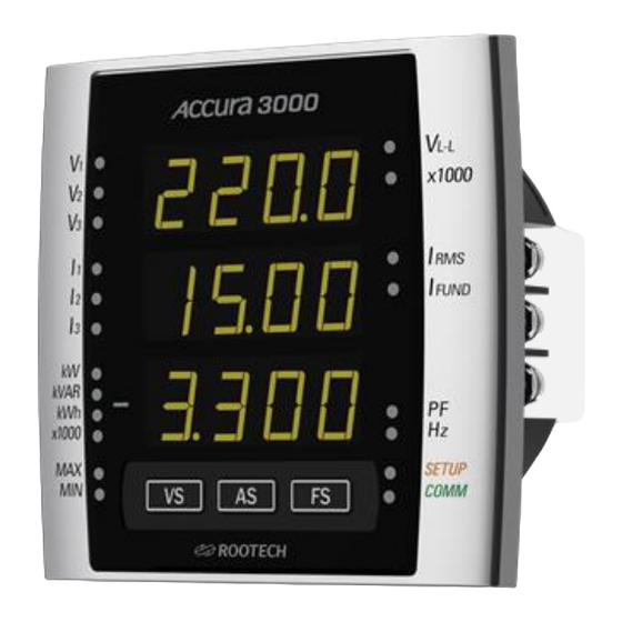
Before You Begin Before installing the meter, observe the instructions in this guide and read the safety precautions presented on the “Installation Considerations” page. Danger Power up after the voltage and current wiring is completed. Meter Overview Fig 1.1 Front Side Fig 1.2 Rear Side Page 17... -
Page 18: Meter Dimensions
Meter Dimensions Fig 1.3 Front View Fig 1.4 Rear View Fig 1.5 Side View Page 18... -
Page 19: Step 1: Mounting
Step 1: Mounting Sequence Remove connector on the bottom of the meter. fit the meter into cutout[ANSI 4” or DIN96] Fig 1.6 ANSI 4” Fig 1.7 DIN96 Note The meter is mounted on switchgear boards (metal cabinet) in electrical facilities. Page 19... -
Page 20: Step 2: Voltage And Current Inputs
Step 2: Voltage and Current Inputs Fig 1.8 Voltage and Current Connector Voltage Input Pin name Connector Terminal block Wire 2.1 to 3.5 mm [ 14 to 12 AWG] Rating 0 ~ 600V 3 ~ L-L[Line to line], 0 ~ 457V 3 ~ L-N[Line to neutral] Burden 0.02VA/phase @220V Impedance... -
Page 21: Current Input
Current Input Pin name 1S, 2S, 3S, 1L, 2L, 3L Connector Terminal block[Busbar] Wire 2.1 to 6 mm [ 14 to 10 AWG] Ratings 5A nominal/ 10A full scale 3 ~ Burden Maximum 0.005A/phase @10A Compliance Pollution degree 2, Installation Category Ⅲ CT[Current Transformer] Compliance UL61010-1;... -
Page 22: Wiring Diagram Using External Pts
Wiring Diagram Using External PTs Danger Failure to observe the following wiring diagrams may result in severe injury or death. Be sure to use shorting block when connecting the meter to CT secondaries. Fig 1.9 Single Phase 2 Wires, Wiring Mode = 1P2U Warning In single phase 2 wires, be sure to use V , 1S, 1L terminals as the above. -
Page 23: Fig 1.10 Three Phase 3 Wire Open Delta Using 2Cts, Wiring Mode = 3P3O
Fig 1.10 Three Phase 3 Wire Open Delta Using 2CTs, Wiring Mode = 3P3O Warning In three phase 3 wire open delta, be sure to connect V to V as the above. Fig 1.11 Three Phase 3 Wire Open Delta Using 3CTs, Wiring Mode = 3P3O Warning In three phase 3 wire open delta, be sure to connect V to V... -
Page 24: Fig 1.12 Three Phase 4 Wires Using 3 Pts And 3 Cts, Wiring Mode = 3P4U
Fig 1.12 Three Phase 4 Wires Using 3 PTs and 3 CTs, Wiring Mode = 3P4U Page 24... -
Page 25: Direct Diagram Using No Pts
Direct Diagram Using No PTs Danger Failure to observe the following wiring diagrams may result in severe injury or death. Be sure to use shorting block when connecting the meter to CT secondaries. Fig 1.13 Single Phase 2 Wire Direct , Wiring Mode = 1P2U Warning In single phase 2 wires, be sure to use V , 1S, 1L terminals as the above. -
Page 26: Fig 1.14 Single Phase 3 Wire Direct Using 2 Cts, Wiring Mode = 1P3U
Fig 1.14 Single Phase 3 Wire Direct Using 2 CTs, Wiring Mode = 1P3U Warning In single phase 3 wires, be sure to use V , 1S, 1L, 3S, 3L terminals as the above. Fig 1.15 Three Phase 3 Wire Open Delta Direct, Wiring Mode = 3P3O Warning In three phase 3 wire open delta direct, use PTs for voltages over 457V [line to line]. -
Page 27: Fig 1.16 Three Phase 3 Wire Open Delta Direct Using 3 Cts, Wiring Mode = 3P3O
Fig 1.16 Three Phase 3 Wire Open Delta Direct Using 3 CTs, Wiring Mode = 3P3O Warning In three phase 3 wire open delta direct, use PTs for voltages over 457V [line to line]. be sure to connect V to V as the above. -
Page 28: Step 3: Wire The Power Supply And Ground Terminal
Step 3: Wire the Power Supply and Ground Terminal Fig 1.18 Wiring of Power Supply and Ground Terminal Power Supply Pin name PP[+/L], PN[-/N] Connector Screw terminal[Pluggable] Wire 1.25 to 3.5 mm [ 24 to 14 AWG] Ratings AC 85 ~ 265V, 50/60Hz ~, DC 100 ~ 300V Compliance Pollution degree 2 Burden... -
Page 29: Step 4: Add A Cover/Power Up The Meter
Step 4: Add a Cover/Power Up the Meter Add a Cover Fig 1.19 Cover Power Up the Meter Close the PT fuses( or direct voltage input fuses). Open the CT shorting blocks. Apply power to the meter. Page 29... -
Page 30: Chapter 3 Meter Operation/Setup
Chapter 3 Meter Operation/Setup Each of these functions can be accomplished by pressing the VS, AS, and FS buttons on the front panel. Display mode View parameter measurements Setup mode Configure parameters Reset mode Reset energy, demand, maximum, and minimum. System mode View meter system information[meter option, firmware version]. - Page 31 x1000 LED When the “x1000” LED of Grout A is lit, multiply the displayed value by 1000 for actual value. When the “x1000” LED of Grout C is lit, multiply the displayed value by 1000 for actual value in fourth LED display. Button Functions in Display Mode Button Function...
- Page 32 Active power kVAR Reactive power Active energy Power factor Frequency Note Energy[kWh, kVARh, kVAh] is read by the total number which join first, second and third LED display together. Example] if first LED display = 1, second LED display = 1200, and third LED display = 1212, then actual value = 112001212.
- Page 33 Group D[Minimum mode] parameter display order Order Group A Parameter A phase minimum current LED off B phase minimum current LED off C phase minimum current LED off LED on A phase minimum fundamental current LED on B phase minimum fundamental current LED on C phase minimum fundamental current Page 33...
-
Page 34: Setup Mode
Setup Mode In Setup mode, You can setup menus, such as PT/CT ratio, wiring, and etc. after mounting the meter. Button Functions in Setup Mode Button Function Enter setup mode by pressing the VS and AS buttons at the same time. -
Page 35: Reset Mode
Three phase 4 wires √ Reset Mode In Reset Mode, you can perform a Energy reset, a Demand reset, or a Maximum/minimum reset. Button Functions in Reset Mode Button Function Enter reset mode by pressing the AS and FS buttons at the same time. -
Page 36: System Mode
System Mode You can view system information, such as product number, version, demand time, frequency selection, and etc. Button Functions in System Mode Button Function Enter System Mode Move to the previous menu screen. Move to the next menu screen. Enter system edit mode to configure the displayed menu value. -
Page 37: Reactive Calculation Method
Device automatically returns to display mode if no button pressing for 10 minutes in setup mode or maximum/minimum mode. Reactive Calculation Method Rootech supports two methods for accurate calculation of reactive power. Method 1: General Calculation Method 1 is used to obtain reactive power, and apparent power by using calculation of vector apparent power. - Page 38 Fig 3.2 P , Q[according to general calculation] Note When phase difference between voltage and current is within 90 degree of lead and lag, power factor is positive. However, when phase difference is more than 90 degree[miswiring, regeneration], power factor and active power are negative. Method 2: Calculation regarding Harmonics Method 2 is used to obtain reactive power from apparent and active power, and the overall apparent power by using calculation of vector apparent power.
-
Page 39: Appendix A Standard Specification
APPENDIX A Standard Specification Voltage Input 0 ~ 600V 3 ~ L-L, 0 ~ 457V 3 ~ L-N [In three phase 3 wire open delta direct, use PTs for voltages over 457V line to line] Calibration: 60 ~ 220V per phase ... -
Page 40: Appendix B Standard Compliance
APPENDIX B Standard Compliance Accuray IEC62053-22 Class 0.5S Safety UL61010-2, 2 edition[IEC61010] IEC61326-1[IEC61000-4-2]: Electrostatic Discharge[ESD] IEC61326-1[IEC61000-4-3]: EM Field IEC61326-1[IEC61000-4-4]: Electric Fast Transient IEC61326-1[IEC61000-4-5]: Surge Immunity IEC61326-1[IEC61000-4-6]: Conducted RF Immunity IEC61326-1[IEC61000-4-8]: Rated Power Frequency Magnetic Field ... -
Page 41: Appendix C Test Report
APPENDIX C Test Report Measurement Test IEC62053-22, Electricity Meter Equipment: active energy for Class 0.5S Current range Power factor Class 0.2S/ 0.5S Accura 3000 0.05A < I < 0.25A ±0.4%/ ±1.0% ±0.4% 0.25A < I < 10.0A ±0.2%/ ±0.5% ±0.2% 0.10A <... -
Page 42: Reliability Test
±1.0% ±1.0% ±1.0% *Voltage : 220V 50% harmonic analysis/ current : 5A 50% harmonic analysis Reliability Test IEC61326, Electrical Equipment for Measurement, Control, and Laboratory- EMC Standard Limit Accura 3000 IEC61000-4-2 Electrostatic Discharge[ESD] 4kV/8kV contact/air 12kV/20kV IEC61000-4-3 EM Field 10V/m... -
Page 43: Index
INDEX A M ANSI 4”, 19 Measurement, 13 Applications, 14 Meter Overview, 17 Assembly/Mounting, 16 Mounting, 19 B P Before You Begin, 17 Parameters, 15 Power Supply, 28 C R Current Input, 21 Rear Side, 17 D Rear View, 18 Reset Mode, 36 DIN96, 19 Direct Diagram Using No PTs, 25... - Page 44 Fax. +82+31-695-7399 www.rootech.com ⓒ 2006 Rootech Inc. All Rights Reserved Accura EMeter, Accura 2300S/2350, Accura 3000, Accura 3300S/3300, Accura 3500S/3500, Accura 3550S/3550, Accura 3700, Accura 5500, Accura 7500 are trademarks of Rootech Inc. Contact rootech for detailed specifications and order information.
Need help?
Do you have a question about the ACCURA 3000 and is the answer not in the manual?
Questions and answers