Table of Contents
Advertisement
Advertisement
Table of Contents

Subscribe to Our Youtube Channel
Related Manuals for Proteus LDT-8850


Summary of Contents for Proteus LDT-8850
- Page 2 Testing specification : EN 957-1, EN 957-6. he GS Mark is a voluntary 3 party inspection and certification scheme for finished products only, according to German Equipment Safety Law - Geratesicherheits - Gesetz. This label ensures products strictly meet the technical safetyrequirements as stipulated by the GSG and the current production line is audited.
-
Page 3: Table Of Contents
......LDT-8850 Monitor ...... -
Page 4: Index
1 INTRODUCTION Thank you very much for choosing PROTEUS products. To secure the safety, pls read the manual and all suggestions carefully before using the product. While you get everything ready, believe that you could enjoy the pleasure of exercise and healthy. -
Page 5: Maintenance
3 MAINTENANCE : a. Maintenance 1. Clean and lubricate the bed of the treadmill every 20 hours of use or monthly, which ever comes first ( SEE TREADMILL LUBRICATION INSTRUCTIONS ). Daily cleaning to the sides of the running mat will prevent much of the dirt from getting underneath the mat. 2. - Page 6 6. Mat slippage may be occurred for a short time. If it persists, adjust the running mat tension as per direction in the owner's manual ( adjust belt tension ). Do not over-tighten, as this will decrease the life of the mat and place undue stress upon the roller bearings. 7.
-
Page 7: Information
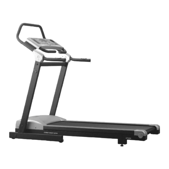
Black powder-body Max. user weight 150kg weight 105kg Folding Foldable a Company information Proteus Sports Lnc. Address: 77-3, Nanshin Village, Linkou, Taipei Hsien, Taiwan, R.O.C. Tel : + 886-2-26093940 26090836 Fax : + 886-2-26093862 26002921 http : //www.proteusfitness.com e-mail : proteus@tpts4.seed.net.tw... -
Page 8: Parts List
LDT-8850 PARTS LIST Description Q'ty Description Q'ty Main frame Side rail Cushion Running belt Square tube cap Rear complete cover Foot unit Front complete cover Front roller set Side Rail fix plate Rear roller set Incline socket set Motor Bushing V- belt Hex. - Page 9 Description Q'ty Description Q'ty Handlebar cover ( inside, right ) Semicircle Hex. Screw Handlebar cover ( outside, right ) Console elbow Big flat spider screw Monitor case Top handle bar Monitor Hex. Screw Safety key Control board Front cover for base Wave filter Square tube cap Inductor...
- Page 10 Description Q'ty Washer Spring washer Semicircle Hex. screw Plastic washer Foam grip PROTEUS plate Fix base for pulse wire Sensor shaft Control wires in upright tube Elevation wires in upright tube Hand pulse sensor wires Control wires on console Elevation wires on console...
-
Page 11: Exploded Drawing
77 11... -
Page 12: Parts List
c Accessories Description Unit Q'ty Part no. Handle bar cover (R) 39 / 40 Handle bar cover (L) 37 / 38 d Parts box / tools Description Unit Q'ty Part no. Semicircle Hex. screw Semicircle Hex. Washer Semicircle Hex. screw Big flat screw Hex. -
Page 13: Assembly - Base
5 Assembly a Note: DO NOT FULLY TIGHTEN ALL FASTENERS UNTIL ASSEMBLY IS DONE. DO NOT PLUG IN POWER SUPPLY UNTIL ASSEMBLY IS COMPLETED. DO MAKE SURE ALL FASTENERS WELL TIGHTENED BEFORE USE. b Machine base Locate the main frame ( 1 ) on level floor, then adjust foot unit ( 4 ) to attach the floor. This could steady the machine without causing wobble. -
Page 14: Upright Tube Assembly
c Upright tube assembly Put 33 upright tube unit ( right ) besides the main frame, connect the frame control wire (A) ( 5-pins ) onto upright tube control wire (A) ( 5 -pins ), then connect elevation wire (B) ( 3-pin ) onto elevation control wire (B) ( 3-pin ) on upright tube unit ( right ). -
Page 15: Assembly - Air Pressure Shaft
d Assembly for air pressure shaft & retractable tube Pull the spring pin ( 66 ) out of the assembling machine, folding the machine upright, one side of air pressure shaft ( 12 ) been assembled on machine base, now, assemble the other side air pressure on main frame ( there is are pressure shafts on each side ). -
Page 16: Assembly - Monitor
e. Monitor Put top handlebar ( 42 ) into upright tube unit ( 32,33 ), with screw ( 43 ) and washer ( 10 ) pre-fix onto upright tube unit ( 33 ) but not fully fastened then put the other side with screw ( 43 ) and washer ( 10 ) pre-fixed onto upright tube unit ( 32 ). -
Page 17: Assembly - Cover
f Cover Put right handle bar cover ( 39,40 ) onto upright tube assembly ( right ,33 ), tighten firmly with screw ( 41 ). Put left handle bar cover ( 37, 38 ) onto upright tube ( left, 32 ), tighten firmly with screw ( 41 ). g Final adjustment Press monitor to upright tube unit ( left and right ) to close together with outside handle bar cover. -
Page 18: Folding
6 Folding and unfolding : CAUTION : Before folding and unfolding, the safety key should be pulled away and the spring pin lock into support shaft. 1 Folding Pull spring pin ( 66 ) out, hold the end machine, folding the machine up till the spring pin lock into support shaft. -
Page 19: Adjust The Machine
7 Adjust the machine Adjust belt tension FACTORS THAT AFFECT MAT ALIGNMENT. 1. The treadmill must be on a level surface. 2. While user running with an uneven stride, the mat should return to center after exercise. 3. Maintain the correct mat tension. In principle, the belt was adjusted by the belt adjusting screw in the back of the machine, if need to adjust the roller, do not adjust the roller by yourself. -
Page 20: Mat Alignment
b MAT ALIGNMENT NOTE : THE ALIGNMENT OF THE TREADMILL MAT MUST BE CORRECTLY ADJUSTED TO ENSURE SMOOTH OPERATION AND TO PREVENT DAMAGE. The treadmill mat must run close to the central position of the treadmill. If the gaps between the mat and the side panel are different, the mat must be aligned. SET THE SPEED OF THE MACHINE AT 4 - 6 km/h, IF THE TREADMILL MAT HAS MOVED TO THE LEFT HAND SIDE, 1. -
Page 21: Incline
c Incline To increase incline: press incline switch to incline level. To decrease incline: press incline switch to decline level. Note : Incline device used over 5 minutes continuously, need off for 20 minutes, to avoid incline device damaged due to overheat. d Instruction of Safety key and pulse The machine works only the safety key ( 62 ) attached to the monitor ( 61 ). - Page 22 Also, while using pulse, user should leave running belt and stand at safe area. PROTEUS had done the best efforts to let customers understanding all the operations and functions before printing this manual. In the mean time, due to our R&D department keeps improving the quality, PROTEUS reserves the right to revise specification, equipment, and maintenance information.
-
Page 23: Ldt-8850 Monitor
LDT-8850 MONITOR The monitor, is designed for motorized treadmills and introduced in the following categories, Key Functions About Displays Operation Instructions Error Massage & Troubleshooting... -
Page 24: Monitor Functions
KEY FUNCTION : There are total 16 buttons including 1 Safety key, 9 Major Function buttons, and 6 quick speed buttons. A. Safety Key : The monitor and the treadmill can be operated only with the key attached and note both of the monitor and the treadmill stop as soon as the key is removed. - Page 25 b. START / STOP : Press this button to start or stop exercise. c. ENTER / REST / PULSE RECOVERY : ENTER FUNCTION : 1. During the stop mode, press this button to confirm your desired program from Manual, P1, P2, P3, P4, P5, P6, P7, P8, P9, U1, U2, 60% MAX H.R., and 85% MAX H.R.
- Page 26 d. MODE : 1. Press this button to choose the function from Manual, P1, P2, P3, P4, P5, P6, P7, P8, P9, U1, U2, 60% MAX H.R., and 85% MAX H.R. LED DISPLAY e. SPEED ¡¶ : 1. In preset status, press this button to increase the setting value of time, distance, calorie, target heart rate and the minimum speed in the P1 to P9.
- Page 27 f. INCLINE Press this button to increased the level of elevation. INCLINE Press this button to decrease the level of elevation. g. COOL DOWN : In the start status, press this button to enter the COOL DOWN function. After press this button, the elevation system will go to level 0 and cool down function will begin to work.
- Page 28 QUICK SPEED : There are 6 speed buttons on the monitor. During the start mode, press the QUICK SPEED button in any time and the motorized treadmill will change the speed immediately to the speed you desired. speed was selected by you. Note : The QUICK SPEED buttons cannot use in the Warm Up and Cool Down program.
-
Page 29: About Display
ABOUT DISPLAY : A. PROGRAM AND MANUAL PROFILE DISPLAY : Display the profile of Manual, P1, P2, P3, P4, P5, P6, P7, P8, P9, U1, U2, 60% MAX H.R., and 85% MAX. The profiles in Manual, P1, P2, P3, P4, P5, U1, and U2 are speed profiles. The profiles in P6, P7, P8, P9, 60% MAX H.R., and 85% MAX H.R. - Page 30 C. DISTANCE Display : Shows the distance with counting up or down. In the setting mode, press SPEED SPEED button to set the desired distance to do the exercise. The range of setting value is from 1.00 KM to 999 KM. By set the value, the distance value will count down. While counting down to 0.00, the monitor will beep and then the treadmill will stop.
- Page 31 E. SPEED Display : a. During the start status, shows the speed that the treadmill is providing. It can be adjusted by pressing SPEED and SPEED keys. b. During the setting status, show the minimum speed of this program. It can by adjusted by pressing SPEED and SPEED keys to set the difficulty of this program the range...
- Page 32 b. In the 60% MAX H.R. and 85% MAX H.R program, while the program window show ENTER AGE press SPEED or SPEED button to setting your age. And then the program window will display ENTER H/R TARGET The window will show the target heart rate value. If you accept this value, press ENTER and go to next setting value.
-
Page 33: Operation Instructions
OPERATION INSTRUCTIONS TO START : Turn on the power and attach the Safety Key to the monitor. And all the windows will fully display for one second; the program will start from manual function. Press the start/stop button to begin excercise. Notice that the machine does not work without the Safety Key attached. - Page 34 CAUTION : Please clip the other end of the Safety Key to user's clothing before exercising to ensure the machine will stop in case the user accidentally runs off the treadmill. Should that happens, the Safety Key will fall off from the monitor and the treadmill will stop at once to avoid further injury.
- Page 35 -- MANUAL FUNCTION-- a. Attach the Safety Key to the monitor. And all the windows will fully display for one second; the program will go to the Manual(M) function. then Press the Enter button. LED DISPLAY b. TIME window will glitter. Press the SPEED or SPEED to set up the desired time to do the exercise.
- Page 36 d. CALORIES window will glitter.Press SPEED or SPEED button to set up the desired CALORIES to be burned. Press ENTER to confirm the setting value of CALORIES. e. The SPEED window will glitter. Press SPEED or SPEED button to choose the Difficulty of this SPEED profile.
- Page 37 g. During the exercise, you can adjust current speed by press the SPEED or SPEED QUICK SPEED button. If you want to skip the setting function, just simply press ENTER to go to the next preset function. You do not need to set up all of these functions before exercise. You can just choose one of them or two of them.
-
Page 38: Program Function
-- PROGRAM FUNCTION P1 TO P9 -- a. Press the mode button to select one of the Preset programs from P1 to P9. b. Press the Enter button. c. TIME window will glitter. Press the SPEED or SPEED to set up the desired time to exercise. - Page 39 the profile will not change anymore even you press the SPEED button. The minimum incline level of this incline profile will display on the PULSE & INCLINE window and the maximum incline level of this incline profile will display on the CALORIE window. You can find the suitable incline program for you.
- Page 40 d. Once reach your target, the motorized treadmill will beep and then stop. You can press START again to reach you next target. The original target your reached will become count up. The other targets you do not reach will continue count down. -- USER SETTING PROGRAM ( U1 U2 ) -- a.
- Page 41 o. Press the START / STOP button to begin exercise. p. During the exercise, you can adjust current speed by press the SPEED or SPEED QUICK SPEED button. If you want to skip the setting function, just simply press ENTER to go to the next preset function. You do not need to set up all of these functions before exercise.
- Page 42 -- HEART RATE CONTROL PROGRAM -- a. Press the mode button to select one of heart rate control programs ( 60% MAX H.R., and 85% MAX H.R ). b. The PROGRAM PROFILE will display ENTER AGE and the PULSE window will flash. The number indicate is Age and the initial value of Age is 25 years old.
- Page 43 Monitor will compare your heart rate and target every 30 seconds. If your actual heart rate is 5 b.p.m. below the target, the elevation will increase 1 level. If your actual heart rate is 5 b.p.m. or more above the target, the elevation will decrease 1 level. If the monitor do not receiver your heart rate signal, the monitor will display every 30 seconds to remind you and the treadmill will keep the same elevation level.
-
Page 44: Program Profile
PROGRAM PROFILE ( Unit = Km / Hr ) KM/H KM/H LEVEL KM/H KM/H LEVEL KM/H LEVEL LEVEL... - Page 45 ERROR MASSAGE & TROUBLESHOOTING E1 : It indicates no signal picked up for 15 seconds and the monitor stops. Solutions : pls consult Dealer. E2 : It indicates the problems of EEPROM IC chip. Either the ID code is incorrect or the data accessed from the IC chip is wrong.
-
Page 46: Warm
WARM - UP GUIDELINES Warming up is an important part of every workout. Warming up prepares the body for more strenuous exercise by increase circulation, deliver more oxygen to the muscles, and raise the body temperature. SUGGESTED STRETCHES The following stretches provide a good warm-up, or cool-down. Move slowly as you stretch-never bounce. - Page 47 TOE TOUCHES Standing with your knees bend slightly, slowly bend forward from the hips. Allow your back and shoulders to relax as you stretch down toward your toes. Go as far as you can and hold for 15 counts, then relax. Repeat three times. Stretches : Hamstrings, Back of Knees, Back QUADRICEPS STRETCH With one hand against a wall for balance, reach behind...
Need help?
Do you have a question about the LDT-8850 and is the answer not in the manual?
Questions and answers
Error 1 keeps appearing and mat stops
Error E1 on the Proteus LDT-8850 indicates that no signal was picked up for 15 seconds, causing the monitor to stop. The solution is to consult the dealer.
This answer is automatically generated