Table of Contents
Advertisement
Quick Links
GTD Series
Installation, Operation,
Maintenance and Parts Manual
CE Certified 230V-50Hz. Infrared Tube Heater.
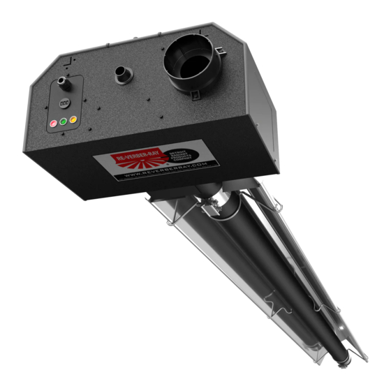
The GTD Series Infrared Tube Heater is a positive pressure, dual-stage radiant heater system. All persons
involved with the installation, operation and maintenance of the heater system must read and understand the
information in this manual.
This heater must be installed and serviced by a Gas Safe Registered Gas Engineer only!
Conversion of the heater for use with other gases must be carried out by a Gas Safe
Registered Gas Engineer. Read these instructions carefully before attempting to install,
operate or service the heater.
This heater is not approved for use in indoor residential applications and must never
be installed indoor in the home. This heater may only be used in outdoor residential
applications or indoor/outdoor commercial (or industrial) applications. Installation in
residential indoor spaces may result in property damage, asphyxiation, serious injury or
death.
In locations used for the storage of combustible materials, signs must be posted to specify
the maximum permissible stacking height to maintain the required clearances from the
heater to the combustibles. Signs must either be posted adjacent to the heater thermostats
or in the absence of such thermostats, in a conspicuous location.
Failure to comply with these warnings and instructions, and those on the heater, could
result in personal injury or death.
For Your Safety
If you smell gas:
• Do not try to light any appliance.
• Do not touch any electrical switch.
• Do not use any phone in your building.
Keep these instructions for future reference.
WARNING
!
• Immediately call your gas supplier from a neighbor's phone.
• Follow the gas supplier's instructions.
• If you cannot reach your gas supplier, call the fire department.
0086
LIOGTD-Rev. 4809
Print: 2/09-r4_11/7/12(DRP)
Replaces: LIOGTD-2/09(DRP)
Advertisement
Table of Contents

Related Manuals for Detroit Radiant Products GTD-20


Summary of Contents for Detroit Radiant Products GTD-20
- Page 1 GTD Series Installation, Operation, Maintenance and Parts Manual CE Certified 230V-50Hz. Infrared Tube Heater. 0086 The GTD Series Infrared Tube Heater is a positive pressure, dual-stage radiant heater system. All persons involved with the installation, operation and maintenance of the heater system must read and understand the information in this manual.
-
Page 2: Table Of Contents
Model High Fire Low Fire Combustion Length (Install Kit ) Number Rate Rate Length (Install Kit ) Chamber Radiant Tubes GTD-20 20 kW 15 kW 6M (20-kit) 9M (30-kit) 12M (40-kit) Aluminized Aluminized or HRT GTD-25 25 kW 15 kW... -
Page 3: Gtd Series Technical Specifications
Specifications - GTD Series Installation, Operation, Maintenance and Parts Manual 1.0 GTD Series Technical Specifications High Max. Rate Rate Proving Baffle Length Injector Air Inlet Min. Gas Burner Burner by Model Length (mm) Model Injector Markings Orfice Air Inlet Pressure Pressure Pressure Pressure... -
Page 4: Safety
Safety - GTD Installation, Operation, Maintenance and Parts Manual 2.0 Safety The intent of this manual is to provide information regarding genral safety, installation, operation and maintenance of this tube heater. You must read and understand all instructions and safety warnings before installing or servicing the tube heater. -
Page 5: Codes And Regulations
Safety - GTD Series Installation, Operation, Maintenance and Parts Manual 2.3 Codes and Regulations The following must be reviewed before installing this heater: • Check the heater rating label on the heater to verify the proper gas to be used. Check other labels on the heater to verify proper mounting and clearance to combustibles. -
Page 6: Clearance To Combustibles
Safety - GTD Installation, Operation, Maintenance and Parts Manual 2.4 Clearance to Combustibles WARNING WARNING This is not an explosion-proof Fire Hazard. Always maintain heater. Do not store or use published clearance to flammable objects, liquids or vapor combustibles. Failure to comply in the vicinity of the heater. - Page 7 Safety - GTD Installation, Operation, Maintenance and Parts Manual Clearance to Combustibles IMPORTANT: For the safe installation of this unit, the clearance to combustibles data below contains clearances that must be maintained. Check the rating plate on the heater to verify the minimum clearance to combustibles and gas type for your model heater.
-
Page 8: Installation
Installation - GTD Installation, Operation, Maintenance and Parts Manual 3.0 Installation 3.1 Design Considerations and Prechecks Placement of infra-red tube heaters is influenced by many factors. Aside from safety factors, considerations such as the number of elbows that are allowed, maximum vent lengths, ducting of combustion air and combining vents are a few examples. - Page 9 Installation - GTD Installation, Operation, Maintenance and Parts Manual Design Scenario A tube heater system is being installed in 27.4m (L) x 15.2m (W) space with 4.3m ceilings. Two overhead doors are located at one end and an equipment storage area exists on one side. The calculated heat load is 110 kw.
-
Page 10: Recommended Mounting Heights
Installation - GTD Series Installation, Operation, Maintenance and Parts Manual Design Criteria 3.2 Recommended Mounting Heights 15 kW 3.0 to 4.6 6.1 x 3.7 3.7 x 3.7 3.0 to 6.1 6.1 to 12.2 20-25 kW 3.3 to 6.1 6.7 x 4.6 6.1 to 9.1 9.1 to 15.2 15 kW... -
Page 11: Hanger Placement And Suspension
Installation - GTD Series Installation, Operation, Maintenance and Parts Manual 3.3 Hanger Placement and Suspension WARNING Improper suspension of the heater may result in collapse and being crushed. Always suspend the appliance from a permanent part of the building structure that can support the total weight and force of the heater. - Page 12 Installation - GTD Series Installation, Operation, Maintenance and Parts Manual Hanger Placement and Suspension Suspension Point Heater Suspension Layout Figure 3.4 • NOTE: A sticker identifying the combustion chamber(s) is located on the swaged end of the tube(s). Suspension Point Radiant Emitter Tube(s) Suspension...
- Page 13 Installationy - GTD Series Installation, Operation, Maintenance and Parts Manual Hanger Placement and Suspension Suspension of the heater must conform to applicable codes referenced in the Safety section and these instructions. Prepare the mounting surface, if necessary, such as: weld blocks, drill holes. Figure 3.5. NOTE: The burner control box and radiant tubes should be in straight alignment and level.
-
Page 14: Optional U-Bend Or Elbow Accessory Configuration
Installation - GTD Series Installation, Operation, Maintenance and Parts Manual 3.4 Optional U-Bend or Elbow Accessory Configuration Figure 3.6 • U-Tube Hanger Mounting Options NOTE: 9M and 15M models require 5EA-SUB accessory package when intalling in a ‘U’ configuation Single Mounting Bracket Brass Knuckle Exhaust... -
Page 15: Radiant Tube Assembly
Installation - GTD Series Installation, Operation, Maintenance and Parts Manual 3.5 Radiant Tube Assembly To install the radiant tubes: Place tubes in hangers with the welded seam facing downward and the swaged end of the tube towards the exhaust end of the heater system (see Figure 3.8). Refer to section 3.8 on page 21 for tube installation sequence. - Page 16 Installation - GTD Series Installation, Operation, Maintenance and Parts Manual Radiant Tube Assembly Slip-fit the radiant tube sections together until tightly connected (install swaged end of each tube towards exhaust end). NOTE: If it is difficult to mate the tubes, they may be installed incorrectly. Center tube clamps over the seams where two radiant tube sections connect.
- Page 17 Installation - GTD Installation, Operation, Maintenance and Parts Manual Radiant Tube Assembly Elbow can be set Figure 3.12 • Elbow and U-Bend Clearances in both directions Dimension A Tube Clamp Tube Clamp U-Bend can be set in both directions Dimension A Tube Clamp 305mm Tube Clamp...
-
Page 18: Burner Control Box Suspension
Installation - GTD Series Installation, Operation, Maintenance and Parts Manual 3.6 Burner Control Box Suspension Suspending the burner control box must be done in accordance with applicable codes listed in the Safety section and these instructions. The burner control box must be in straight alignment with radiant tubes and level. Contact your local distributor or the factory to see if your application allows for the rotation of the burner control box. -
Page 19: Reflector Assembly
Installation - GTD Series Installation, Operation, Maintenance and Parts Manual 3.7 Reflector Assembly To install the reflectors: Attach reflector center supports onto radiant tubes. Slide each reflector section through the hangers and adjust the reflector tension spring into the V-groove on the top of the reflector. - Page 20 Installation - GTD Series Installation, Operation, Maintenance and Parts Manual Reflector Assembly Common Optional Accessories Reflector Accessories Description Part # Elbow Reflector* 90° bend, highly polished aluminum reflector elbow. Designed to fit atop one elbow accessory fitting. U-Reflector* 180° bend, highly polished aluminum reflector U-bend. Designed to fit atop one U-bend accessoy fitting.
-
Page 21: Baffle Assembly And Placement
Installation - GTD Series Installation, Operation, Maintenance and Parts Manual 3.8 Baffle Assembly and Placement Secured Joints and Baffle Location for Reflectors NOTICE Different inputs and models utilize different baffle lengths. Remove all enclosed baffle sections from box and retain with applicable heater. - Page 22 Installation - GTD Series Installation, Operation, Maintenance and Parts Manual Baffle Assembly and Placement To assemble the baffles: NOTE: Baffles may be inserted into the tube while being assembled. Determine the number of baffles needed for your model number. Remove one 840mm baffle section if heater is installed with an elbow or U-bend accessory.
-
Page 23: Flueing
Installation - GTD Series Installation, Operation, Maintenance and Parts Manual 3.9 Flueing WARNING Insufficient flueing and/or improperly sealed flues may release gas into the building which could result in health problems, carbon monoxide poisoning or death. Improper flueing may result in fire, explosion, injury or death. Seal flue pipes with high temperature sealant and three (3) sheet metal screws. - Page 24 Installation - GTD Series Installation, Operation, Maintenance and Parts Manual Flue Assembly Figure 3.20 • Flue Requirements: Rooftop Flue Cap 610 mm Min. Roof Storm Collar Adjustable Roof Flashing 26 mm. minimum clearance Twin Skin Flue 26 mm. minimum clearance Ceiling Ring Spacer Heater Twin Skin to Single Skin Adapter...
- Page 25 Installation - GTD Series Installation, Operation, Maintenance and Parts Manual Flue Assembly Flue Termination • Flue must terminate a minimum of 1200mm below, 1200mm horizontally from or 300mm above any window or door that may be opened and gravity air inlet into the building. •...
- Page 26 Installation - GTD Series Installation, Operation, Maintenance and Parts Manual Flue Requirements Figure 3.23 • Sidewall Flueing - Side View Building (Combustible) Overhang Sidewall Twin Skin to Single Skin Adapter 1000mm min. Heater 150mm min. Sidewall Flue Cap Wall Thimble Single Skin Flue Twin Skin Flue Optional Unflued Operation...
-
Page 27: Combustion Air Requirements
Installation - GTD Series Installation, Operation, Maintenance and Parts Manual Combustion Air Requirements NOTICE This heater has a factory preset air orifice for proper combustion air supply. If combustion air is to be provided for a tightly closed area, 440 sq. mm of free air opening must be provided for each kW of heater input. - Page 28 Installation - GTD Series Installation, Operation, Maintenance and Parts Manual Combustion Air Requirements Guidelines: Limitations for length and size of combustion air intake duct Single Heater Intake Dual Heater Intake Air Intake Duct Size Max. Intake Length Duct Size Max. Intake Length 100mm 6100mm 100mm.(single)/150mm.(dual)
-
Page 29: Gas Supply
Installation - GTD Series Installation, Operation, Maintenance and Parts Manual Gas Supply WARNING Improperly connected gas lines may result in fire, explosion, poisonous fumes, toxic gases, asphyxiation or death. Connect gas lines in accordance to national, state, provincial and local codes. - Page 30 Installation - GTD Series Installation, Operation, Maintenance and Parts Manual Gas Supply Adjusting Burner Pressure: Remove the lid to the valve compartment. Open the pressure nipple (Figure 3.29-A) and connect pressure meter tube. Remove the cap over the adjusting screws on the gas valve pressure regulator. Place a 10mm spanner (wrench) on the outer adjusting nut and a screwdriver on the black inner adjusting screw.
- Page 31 Installation - GTD Series Installation, Operation, Maintenance and Parts Manual Gas Connection WARNING Failure to install, operate or service this appliance in the approved manner may result in property damage, injury or death. Only trained, qualified gas installation and service personnel may install or service this equipment.
- Page 32 Installation - GTD Series Installation, Operation, Maintenance and Parts Manual Gas Supply CAUTION When using a stainless steel flexible connector, do not attach the connector nuts directly to the gas pipe supply. Connector nuts must be installed to an approved adapter. Attach the flexible connector to the adapter and burner control box inlet.
-
Page 33: Electrical Requirements
Installation - GTD Series Installation, Operation, Maintenance and Parts Manual 3.12 Electrical Requirements • Verify that the heater’s voltage (as listed on the rating plate) matches that of your application. • Heaters operate on 230 volts, 50Hz., single phase. The amperage requirement is 0.6 Amps running current per heater. - Page 34 Installation - GTD Series Installation, Operation, Maintenance and Parts Manual Internal Wiring Diagrams If any of the original wire as supplied with this appliance must be replaced, it must be replaced with wiring material having a temperature rating of at least 105°C. Figure 3.33 - Internal Wiring Diagram 230V Amb M Lgt...
-
Page 35: Operation
Operation - GTD Series Installation, Operation, Maintenance and Parts Manual 4.0 Operation WARNING This heater is not equipped with a pilot ignition system. Do not attempt to light the system manually. Commissioning Procedures: Ensure that ball valve to the heater is turned “OFF”. Purge air from the gas supply line and test for gas soundness in accordance with relevant Standards. -
Page 36: Maintenance
Maintenance - GTD Series Installation, Operation, Maintenance and Parts Manual 5.0 Maintenance WARNING Personal injury or death may result if maintenance is not performed by properly trained gas installer or service personnel. Contact the installing distributor or place of purchase for service. -
Page 37: Troubleshooting Guide
Maintenance- GTD Series Installation, Operation, Maintenance and Parts Manual Troubleshooting Guide NOTE: Contact appliance manufacturer prior to replacing parts other than those specified in this manual. Chart 5.1 Troubleshooting Guide Symptom Possible Cause Corrective Action Thermostat closed, fan doesn’t • Blown fuse. •... -
Page 38: Parts
Parts - GTD Series Installation, Operation, Maintenance and Parts Manual 6.0 Parts Figure 6.1 • Burner Assembly Components 3060 3094 3098 3005A 3097A 3011 3646 3044 3008 640B 383B 3096A 3094 3580 3001 3012 651A, 3002A 1018 3651 3650 664D/E/F 3010 3099 3070, 3072... -
Page 39: Tube And Reflector Components
Parts - GTD Series Installation, Operation, Maintenance and Parts Manual Basic Parts List Figure 6.2 • Tube & Reflector Components 20C/D* 26A/D* 26A/B/C/E* 21B, 220 Part # Description Part # Description TP-615 220-240V 50/60Hz Fan TP-3010 Service Panel Hinge TP-628A Red Indicator Light TP-3011 Electrode Set Igniter Box... -
Page 40: Gtd Series Kit Contents
Reflector End Cap Clips TP-633 Shut-Off Valve* TP-683 S.S. Flexible Gas Connector* LIOGTD GTD IOM Filled By: *Optional Accessory © 2012 Detroit Radiant Products Co. 21400 Hoover Road • Warren, MI 48089 Phone: (586) 756-0950 Fax: (586) 756-2626 www.detroitradiant.com • sales@detroitradiant.com...
Need help?
Do you have a question about the GTD-20 and is the answer not in the manual?
Questions and answers