Detroit Radiant Products Re-Verber-Ray HL2 Series Insert Manual
Hide thumbs
Also See for Re-Verber-Ray HL2 Series:
Table of Contents
Advertisement
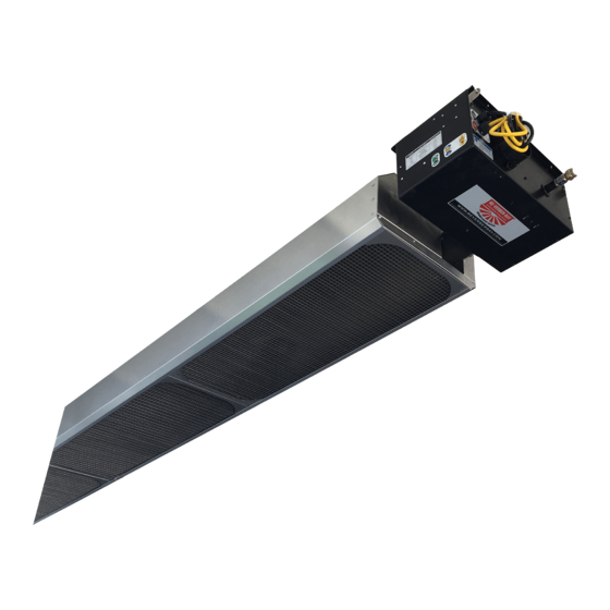
HL2 Series
Insert Manual
For complete installation instructions, see the Tube Heater General Manual
that accompanies this Series Insert Manual.
The HL2 Series Infrared Tube Heater is a positive pressure, two-stage radiant heater system. This insert
manual is a supplement to the Tube Heater General Manual and provides specific information related to
the HL2 Series model. All persons involved with the installation, operation and maintenance of the heater
system must read and understand the information in this insert manual and the accompanying Tube
Heater General Manual.
Improper installation, adjustment, alteration, service or maintenance can cause
property damage, injury or death. Read the installation, operation and maintenance
instructions thoroughly before installing or servicing this equipment.
This heater must be installed and serviced by trained gas installation and service
personnel only. Failure to comply could result in personal injury, asphyxiation, death,
fire or property damage.
In locations used for the storage of combustible materials, signs must be posted to
specify the maximum permissible stacking height to maintain the required clearances
from the heater to the combustibles. Signs must either be posted adjacent to the
heater thermostats or in the absence of such thermostats, in a conspicuous location.
Not for residential use! Do not use this heater in the home, sleeping quarters,
attached garages, etc. Installation of a commercial tube heater system in
residential indoor spaces may result in property damage, serious injury,
asphyxiation or death.
For Your Safety
If you smell gas:
• Do not try to light any appliance.
• Do not touch any electrical switch.
• Do not use any phone in your building. • If you cannot reach your gas supplier, call the fire department.
INSTALLER: Present this manual to the end user.
Keep these instructions in a clean and dry place for future reference.
Model#: ___________________ Serial #: _________________________
!
WARNING
!
• Immediately call your gas supplier from a neighbor's phone.
• Follow the gas supplier's instructions.
(located on rating label)
LIOHL2a-Rev. 24414
Print: 2M-8/13_r7_10/19 (CDS)
Replaces: LIOHL2-2M-9/09(CDS)
Advertisement
Table of Contents

Related Manuals for Detroit Radiant Products Re-Verber-Ray HL2 Series


Summary of Contents for Detroit Radiant Products Re-Verber-Ray HL2 Series
- Page 1 HL2 Series Insert Manual For complete installation instructions, see the Tube Heater General Manual that accompanies this Series Insert Manual. The HL2 Series Infrared Tube Heater is a positive pressure, two-stage radiant heater system. This insert manual is a supplement to the Tube Heater General Manual and provides specific information related to the HL2 Series model.
-
Page 2: Table Of Contents
Series Contents .0 Safety..............3 Safety Labels and Their Locations . -
Page 3: Safety
Table is upgraded to 409 Stainless Steel DESIGN COMPLIES WITH: ANSI Z83.20-2008-GAS FIRED LOW INTENSITY INFRA-RED HTR. AMPS - Running: Minimum Inlet Pressure: Maximum Mounting Angle: DETROIT RADIANT PRODUCTS COMPANY Serial No.: 0914XXXXXXXXXX 0001 21400 HOOVER ROAD - WARREN, MI (586) 756-0950 www.drp-co.com DEGREES 5.0 Inches... -
Page 4: Clearances To Combustibles
Series Safety • Safety Labels and Their Locations • Clearances to Combustibles F/N: LLTB007(2) LED CODE FAULT STATUS FAULT CODE DELAY Initial flash on power up, Normal operation Immediate then steady off Steady on Module failure / Internal fault Immediate 1 flash Ignition failure 30-32 minutes... - Page 5 Series Safety • Clearances to Combustibles When installing the tube heater system, clearances to combustibles for the model tube heater and configuration must be maintained. Refer to Chart 1.1 below to determine the required distances for your model. Chart 1.1 •...
-
Page 6: Installation
Series Installation • Electrical Requirements Installation WARNING Improper installation, adjustment, alteration, service, or maintenance can cause property damage, serious injury, or death. Read and understand the installation, operating, and maintenance instructions thoroughly before installing or servicing this equipment. Only trained, qualified gas installation and service personnel may install or service this equipment. -
Page 7: Wiring
Series Installation • Wiring Wiring WARNING Electric Shock Field wiring to the tube heater must be connected and grounded in accordance with national, state, provincial, and local codes, and to the guidelines in the Tube Heater General Manual and Series Insert Manual. In the United States refer to the most current revisions to the ANSI/NFPA 70 Standard and in Canada refer to the most current revisions to the CSA C22.1 Part I Standard. - Page 8 Installation Series • Wiring Before field wiring this appliance - Check existing wiring; replace if necessary. Note: If any of the original wire supplied with the appliance must be replaced, it must be replaced with wiring material having a rating of at least 600 V, 105° C. Figure 2.2 •...
- Page 9 Series Installation • Wiring Figure 2.3 • Alternative Wiring Diagrams A. Micro 60U-24 Ladder Diagram - With Relay Board 120VAC 120VAC TRANSFORMER RELAY BOARD 24VAC IGNITOR FLAME THERMOSTAT PRESSURE TERMINAL SWITCH BLOWER STAGE 2-STAGE T'STAT LIGHT (FIELD SUPPLIED) LIGHT MICRO 60U-24 24VAC IGNITION MODULE...
-
Page 10: Specifications
Series Installation • Product Specifications Specifications Chart 2.1 • Specifications HL2-20-65 N or LP 65,000 50,000 21’-7” 13’-0” 9’ to 14’ Alum Alum 20.2 HL2-20-75 N or LP 75,000 50,000 21’-7” 13’-0” 10’ to 15’ Alum Alum 20.2 HL2-20-80 N or LP 80,000 52,000 21’-7”... -
Page 11: Tube Installation Sequence
Installation Series • Tube Sequence • Heater Length Tube Installation Sequence Figure 2.4 • Tube Installation Sequence Important! The combustion chamber & radiant tube sections must be installed in the following order: 20 Foot 30 Foot 40 Foot Stainless Steel Clamp on 150-175 MBH models (P/N: TP-220). 50 Foot Stainless Steel Clamp on 150 - 200 MBH models (P/N: TP-220). -
Page 12: Operation
Series HL2 Series Operation • Sequence of Operation • Thermostat • Diagnostics Operation Sequence of Operation Standby: The circuit board continually checks for internal faults, circuit integrity, and relay contact positioning. Starting Circuit: Upon a call for heat, the control verifies that the differential switch is in the proper position (open). -
Page 13: Diagnostics
Series Operation • Diagnostics Diagnostics Lockout: The controls will automatically lockout the heater system when an external or system fault occurs. There are two types of lockout: Soft Lockout: The heater will attempt to light three times. In the event of a failed attempt to light, (gas pressure, valve, no flame sense etc.), the heater will enter Soft Lockout mode for 30 minutes and then attempt to light three more times before entering Hard Lockout mode. -
Page 14: Troubleshooting Guide
Series Troubleshooting Guide Troubleshooting Guide Turn up thermostat. Is the power at the Does the heater have a relay board? Does the fan heater 120 V? (identified with orange crescent blower turn on? next to the terminal plug). Find the source of the electrical problem between panel and heater. Find the source of the Is there 120 V on the Is the power across... - Page 15 Series Troubleshooting Guide Bypassing any switch is intended for testing purposes only. Do not leave switch bypassed NOTICE during normal operation or the heater’s built-in safety mechanisms will be compromised. With Relay Board: Without Relay Board: Start Process Corrective Process Corrective Question Question...
- Page 16 Series Troubleshooting Guide Continued from page 14 After ignitor is Test for 24 V at valve opening period (usually 45 to 60 seconds warmed up, does after power to heater). Is there 24 V to valve for 8 seconds? gas valve open? Replace circuit board.
- Page 17 Series Troubleshooting Guide Check to make sure gas pressure is within minimum and maximum inputs, as indicated on heater’s rating plate. Replace gas valve. Is gas pressure OK? Correct problem. Were the gas lines purged of air? Purge gas line. Is the heater properly With microampmeter, check DC Check to make sure flame...
-
Page 18: Parts
Series Parts • Heater Components and Parts List Parts NOPS Figure 5.1 • Burner Assembly Components 802, 802A 383A 222A 201B or 3072 83, 83A TP-840A, 841A 208A Chart 5.1 • Parts List Part No. Description Part No. Description TP-1 Control Box Cover TP-26E 10 ft. - Page 19 Series Parts • Heater Components and Parts List Figure 5.2 • Tube and Reflector Components 20C, 20D 106 105 26A, 26D 21B, 220 26A, 26B, 26E Part No. Description Part No. Description TP-113 Reflector Tension Spring TP-321 Ignition Plate Gasket TP-114 Plastic Air Orifice with Screen TP-383A...
-
Page 20: Kit Contents Check List
• 10 years - Stainless steel burner • Commercial approval • See page 40 of the General Tube Heater Manual for terms and conditions. © 2019 Detroit Radiant Products Co. 21400 Hoover Road • Warren, MI 48089 Phone: (586) 756-0950 Fax: (586) 756-2626 www.detroitradiant.com • sales@drp-co.com...
Need help?
Do you have a question about the Re-Verber-Ray HL2 Series and is the answer not in the manual?
Questions and answers