Table of Contents
Advertisement
Quick Links
Detroit Radiant Products Company
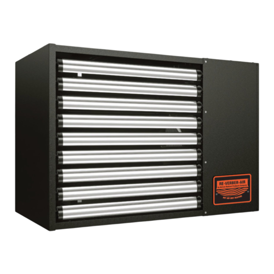
FA Series
The FA Series are gas-fired unit heaters. This manual provides specific information related to the FA Series
models. All persons involved with the installation, operation, and maintenance of the heater system must
read and understand the information in this manual.
Improper installation, adjustment, alteration, service, or maintenance can cause
property damage, serious injury, or death. Read and understand the installation,
operating, and maintenance instructions thoroughly before installing or servicing this
equipment.
This heater must be installed and serviced by trained gas installation and service
personnel only. Failure to comply could result in personal injury, asphyxiation, death,
and fire or property damage.
Do not store or use gasoline or other flammable vapors and liquids in the vicinity of this
or any appliance.
Do not use this heater in indoor living or sleeping quarters! Installation of this unit in a
residential indoor living space may result in property damage, serious injury,
asphyxiation, or death.
For Your Safety
If you smell gas:
• Open windows.
• Do not touch any electrical switch.
• Extinguish any open flame.
• Do not use any phone in your building.
INSTALLER: Present this manual to the end user.
Keep these instructions in a clean, dry place for future reference.
Model#: ___________________Serial #: _________________________
Manual
WARNING
!
• Immediately call your gas supplier from a neighbor's phone.
• Follow the gas supplier's instructions.
• If you cannot reach your gas supplier, call the fire department.
(located on rating label)
Installation, Operation,
Maintenance, and Parts
LIOFA-Rev. 00413
Print: 1M-10/22_r1-01/24(CDS)
Replaces: LIOFA-2M-12/15(CDS)
Advertisement
Table of Contents

Related Manuals for Detroit Radiant Products FA Series


Summary of Contents for Detroit Radiant Products FA Series
- Page 1 Installation, Operation, Maintenance, and Parts The FA Series are gas-fired unit heaters. This manual provides specific information related to the FA Series models. All persons involved with the installation, operation, and maintenance of the heater system must read and understand the information in this manual.
-
Page 2: Table Of Contents
Series Table of Contents Contents 1.0 Introduction ..............3 Overview. -
Page 3: Introduction
The intent of this manual is to provide information regarding safety, design guidelines, installation, operation, and maintenance of FA Series gas-fired unit heaters. You must read and understand the instructions and all safety warnings before installing the gas-fired unit heater. This manual is property of the owner and must stay with the owner or unit after installation is complete. -
Page 4: Initial Installation Considerations And Pre-Checks
Introduction • Initial Installation Considerations and Pre-Checks Series Initial Installation Considerations and Pre-Checks WARNING Improper installation, adjustment, alteration, service, or maintenance can cause property damage, serious injury, or death. Read and understand the installation, operating, and maintenance instructions thoroughly before installing or servicing this equipment. Only a trained, qualified installation or service personnel may install or service this equipment. -
Page 5: Product Specifications
Product Specifications Product Specifications FA Series heatersare single input, warm air heaters with an average thermal efficiency of 80%, unless otherwise indicated on the rating label. All units are to be supplied with single-phase, 60 Hz, 120 VAC power. The exterior of all models is finished with industrial-grade colored enamel. For specific information on each model, see Chart 1.1, below. -
Page 6: Safety Labels And Their Locations
INCH INCH This appliance requires a Category I or III venting system. Refer to pages 23-33 of the manufacturer’s installation instructions for proper vent installation. DETROIT RADIANT PRODUCTS COMPANY FOR COMMERCIAL/INDUSTRIAL USE. 21400 HOOVER ROAD - WARREN, MI 48089 FOR INDOOR USE ONLY. - Page 7 Series Introduction • Safety Labels and Their Locations F/N: LLUHCL001c Safety & Operating Instructions F/N: LLUH007c Vent Length Notice F/N: LLWUH001 Wiring Diagram Status LED Each of the following status codes is determined by the number of fl ashes on the status light. See the Manual for additional information. Status LED Each of the following status codes is determined by the number of fl...
-
Page 8: Safety
Commercial / Industrial FA Series heaters are designed and certified for use in industrial and commercial buildings, such as warehouses, manufacturing plants, aircraft hangars, and vehicle maintenance shops. For maximum safety, the building must be evaluated for potential problems before installing the heater system. This unit is certified for use as furnished by the manufacturer. -
Page 9: Standards, Certifications, And Government Regulations
Series Safety • Standards, Certifications, and Government Regulations Standards, Certifications, and Government Regulations Installation of this heater must conform to all applicable local, state, and national specifications, regulations, and building codes. Contact the local building inspector and/or fire marshal for guidance. In the absence of local codes, the installation must conform to the latest edition of: United States: National Fuel Gas Code, ANSI Z223.1 (NFPA 54). - Page 10 Safety • Standards, Certifications, and Government Regulations Series Chart 2.2 • Standard and Code Installation Guidelines • Building Location Building Guidelines Location High Guidelines Altitude Installation of this heater is approved, without modifications, for elevations up to 2,000 feet (610 m) above MSL (sea level) in the United States. For elevations above 2,000 feet, the heater input must be derated.
-
Page 11: Clearances To Combustibles
Series Safety • Clearances to Combustibles Clearances to Combustibles A critical safety factor to consider before installation is the clearances to combustibles. Clearance to combustibles is defined as the minimum distance that must exist between the specified feature of the heater and any combustible items. -
Page 12: Installation
Installation • Louver Installation Series Installation Louver Installation For 0° Mounting: Guide the plunger side of the louver into the larger of the two holes (as shown in Figure 3.1). The louver arch must face up. When the plunger is in the hole, press the louver in, collapsing the internal spring of the plunger. Guide the other side of the louver into place by aligning the indexing winglet (as shown in Figure 3.2). -
Page 13: Hanging The Unit Heater
Series Installation • Hanging the Unit Heater Hanging the Unit Heater NOTICE High humidity or saltwater atmospheres will accelerate heater corrosion and reduce useful life. Do not install the heater in locations where water (in the form of rain, drips, or spray) could fall onto the gas ignition components. - Page 14 Installation • Hanging the Unit Heater Series For FA-100 to FA-250 Models: Determine desired mounting points and mark the locations for the hanging points. Prepare the mounting surface. If necessary, weld blocks, drill holes, or install additional bracketing or steel channel. Fasten beam clamp, screw hook, turnbuckle, steel channel, or other anchoring device to the suspension points.
- Page 15 Series Installation • Hanging the Unit Heater For FA-300 and FA-400 Models: Determine desired mounting points and mark the locations for the hanging points. Prepare the mounting surface. If necessary, weld blocks, drill holes, or install additional bracketing or steel channel. Fasten beam clamp, screw hook, turnbuckle, steel channel, or other anchoring device to the suspension points.
-
Page 16: Recommended Mounting Heights
Installation • Recommended Mounting Heights • Gas Supply Installation Instructions Series Recommended Mounting Heights Chart 3.1 • Recommended Mounting Heights* Typical Approximate Average Air Temperature Model Mounting Height Heat Throw Rise FA-100 12 to 14 ft. 43 ft. 50°F FA-125 14 to 16 ft. - Page 17 Series Installation • Gas Supply Installation Instructions The gas supply to the heater must be connected and tested in accordance with national, state, provincial, and local codes, along with guidelines in this manual. In the United States, refer to ANSI Z223.1/NFPA 54 (latest edition).
- Page 18 175’ 200’ FA Series heaters are equipped to receive a gas supply line nipple of either ½” NPT or ¾” NPT Schedule 40 metallic pipe. All piping must be installed in accordance with the requirements outlined in the National Fuel Gas Code ANSI/Z223.1 (latest edition) or CSA-B149.1 and B149.2 (latest edition).
-
Page 19: Leak Testing
Series Installation • Gas Supply Installation Instructions • Leak Testing Figure 3.6 • Recommended Hardware–Manual Shut Off and Sediment Trap Flow of Shut Off To Unit Ground Joint Union Gas Supply Line 1/8” NPT Test Connection (Plugged) 3” Minimum Sediment Trap Leak Testing WARNING Use a soap solution or equivalent for leak testing. -
Page 20: Electrical Requirements And Wiring Diagrams
Installation • Electrical Requirements and Wiring Diagrams • Internal Wiring Diagram Series Electrical Requirements and Wiring Diagrams WARNING Shock hazard. Disconnect power supply before making wiring connections to prevent electrical shock and equipment damage. Any original factory wiring that requires replacement must be replaced with wiring material having a temperature rating of at least 105°C. -
Page 21: Field Wiring Supply Voltage
Series Installation • Field Wiring Supply Voltage Field Wiring Supply Voltage Before proceeding with electrical connections, ensure that the supply voltage, frequency, phase, and current capacity meet the requirements specified on the rating plate. A dedicated line voltage supply with properly sized wire shall run directly from the main electrical panel to the heater. - Page 22 Installation • Field Wiring Supply Voltage Series Figure 3.8 • Field Wiring Flexible Conduit BX or Romex Connector Junction Box Ground Green White to L2 (Ground) (Neutral) Black to L1 (Hot) Connect wires together with UL Listed wire connectors. Green to Ground Black to L1 White to L2 NOTE: A UL Listed switch may be installed in the 2”...
-
Page 23: Thermostat Connection
NOTE: Different thermostats operate according to their particular features. Refer to the thermostat’s specifications for details. Each FA Series heater requires a single stage thermostat rated for 24 VAC to operate. The heater comes standard with a terminal strip for making thermostatic connections, located on the back panel. The... -
Page 24: Thermostat Location
Installation • Thermostat Location Series Thermostat Location The location of the thermostat should be determined by the desired heating requirements and be mounted on an inside wall five (5) feet above the finished floor. Locate the thermostat in a conspicuous location, away from where it could be influenced by heat from the unit or other sources, as this may cause the unit to short cycle. -
Page 25: Venting
Replacing Existing Equipment Venting FA Series heaters must be vented as described here to properly direct the flue gases from the unit to the outside atmosphere. Venting can terminate vertically through the roof (up) or horizontally through a sidewall (sideways). -
Page 26: General Venting Requirements
Series General Venting Requirements The venting system for FA Series heaters may terminate vertically through the roof or horizontally through a sidewall, and may be individually or commonly vented. Configuration of the vent termination determines the category type. All model heaters must be installed according to the requirements of this section, as well as the requirements of the applicable category, as described in this manual. - Page 27 Series Installation • General Venting Requirements Figure 3.10 • General Vent Requirements Vent Cap 24 in. Min.* Roof* Storm Collar Adjustable Roof Flashing 1 in. Minimum Clearance Double Wall B-Vent 1 in. Minimum Clearance Fire Stop Spacer Heater B to C Adapter Clean-Out Tee Fitting Clean-Out Cap #8 Sheet Metal Screws (field supplied)
-
Page 28: Vertical Venting (Category I)
An appliance that operates with a non-positive vent static pressure and with a vent gas temperature that avoids excessive condensate production in the vent is said to be Category I. An FA Series heater is considered a Category I appliance if the venting system meets all of the following criteria: •... -
Page 29: Horizontal Venting (Category Iii)
An appliance that operates with a positive vent static pressure and with a vent gas temperature that avoids excessive condensate production in the vent is said to be Category III. An FA Series heater is considered a Category III appliance if the venting system meets all of the following criteria: •... - Page 30 Installation • Horizontal Venting (Category III) Series All horizontal Category III vents must be terminated with a Simpson-Duravent sidewall vent cap (P/N: SWD-4 for 4-inch venting or P/N: SWD-6 for 6-inch venting). Vent Locations and Clearances: • A Category III venting system may NOT be common vented, and no other gas units are allowed to be vented into it.
-
Page 31: Common Venting (Category I)
Series Installation • Common Venting (Category I) Common Venting (Category I) The common vent system and all attached appliances must be Category I. The vent connector should be routed in the most direct route from the units to the common vent. Where two or more vent connectors enter a common gas vent or chimney flue, the smaller connector shall enter at the highest level consistent with the available head room or clearance to combustible material. -
Page 32: Concentric Venting
Installation • Concentric Venting • Combustion Air Requirements Series Concentric Venting Contact the factory for concentric venting requirements. Combustion Air Requirements Combustion air may be supplied to the heater by indoor or outdoor means. Follow these guidelines and all applicable codes for all models prior to installing the combustion air duct work. Local codes may vary. In the absence of local codes, refer to and comply with the National Fuel Code ANSI Z223.1/NFPA 54 (latest edition) or the National Standards of Canada. -
Page 33: Separated Combustion Systems
Separated Combustion Systems Separated Combustion Systems FA Series heaters come with a factory-installed combustion air adapter for attaching air intake ducts to the heater. Attach the air intake duct material to the adapter with three (3) non-corrosive sheet metal screws. If necessary, drill pilot holes prior to attaching the air intake ducts. - Page 34 Installation • Separated Combustion Systems Figure 3.14 • Outside Combustion Air Sidewall Intake–Side View Exhaust Listed Wall Thimble Terminal Cap (P/N: SWD-4 or SWD-6) Clean-Out 12 in. 6 in. Min. Min. 3 ft. Min. Combustion Air Intake Cap 1/4 in. Pitch per Foot (P/N: SWD-4 (Upward or Downward) or SWD-6)
-
Page 35: Room Air Combustion Systems
Series Installation • Room Air Combustion Systems Room Air Combustion Systems When operating this unit as a room air combustion appliance, the factory installed air intake collar may be removed and the required air for combustion can be taken into the appliance from the space, so long as it is not a confined space (see Figure 3.16). -
Page 36: Unit Start-Up (Commissioning)
Installation • Unit Start-Up (Commissioning) • Pre-Start Up Checks Series Unit Start-Up (Commissioning) WARNING Improper installation, adjustment, alteration, service, or maintenance can cause property damage, serious injury, or death. This heater must be installed and serviced by a trained gas installation and service personnel only. CAUTION Shock Hazard. -
Page 37: Verify Proper Inlet Pressure
Series Installation • Verify Proper Inlet Pressure Verify Proper Inlet Pressure Before starting up the unit, smell all around the unit heater for gas. Be sure to smell next to the floor because some gas is heavier than air and will settle on the floor. When turning the gas shut off valve, only use your hand. -
Page 38: Verify Manifold Pressure
Installation • Verify Manifold Pressure Series Replace the inlet pressure tap plug on the gas control valve. Leak check the re-installed pressure tap plug using a soap solution or equivalent method as described in ANSI Z223.1/NFPA 54 (latest edition). Figure 3.17 •... -
Page 39: Prior To Leaving The Job Site
Series Installation • Verify Manifold Pressure • Prior to Leaving the Job Site Verify manifold pressure: After the unit has successfully ignited, wait five (5) minutes prior to taking any readings. The unit heater must be in a steady state of operation prior to taking a manifold pressure reading. While waiting for the unit to stabilize, observe the characteristics of the flame. -
Page 40: High Altitude Operation
FA Series heaters are factory configured for altitudes from 0–2,000 ft. above sea level. If the unit heater is being installed at an elevation above 2,000 ft., the input rate will have to be de-rated to ensure proper operation. - Page 41 Series Installation • High Altitude Operation Chart 3.6 • High Altitude Conversion Kits for Elevations of 4,501 to 7,000 Feet Kit Number Orifice Size Number of Model Orifices Natural Gas Propane Natural Gas Propane FA-100 HKN-44-4 HKP-54-4 44 DMS 54 DMS FA-125 HKN-44-5 HKP-54-5...
-
Page 42: Operation
Operation • Sequence of Operation Series Operation WARNING This appliance does not have a pilot ignition. It is equipped with an ignition device which automatically lights the burner. Do not attempt to light the system by hand. Sequence of Operation Standby: The ignition control continually checks for internal faults, circuit integrity, and relay contact positioning. -
Page 43: Shutdown Procedures
Series Operation • Shutdown Procedures Shutdown Procedures Set the thermostat to the lowest setting. Turn OFF all electrical power to the appliance if service is to be performed. Turn manual shut off knob clockwise to OFF. Do not force. If the heater’s internal diagnostic LED displays any of the signals listed in Charts 4.1–4.2 address the indicated problem as outlined. -
Page 44: Troubleshooting Guide
Troubleshooting Guide Series Troubleshooting Guide Limit switch is open or pressure Turn on control Find source of switch is stuck closed. Find faulty device for heat. electrical problem. switch and repair. Does the draft Does the heater have 120 VAC at Does the air circulating fan inducer motor the main power connection? - Page 45 Series Troubleshooting Guide Bypassing any switch is intended for testing purposes only. Do not leave switch bypassed during NOTICE normal operation or the heater’s built-in safety mechanisms will be compromised. Process Start Corrective Question Question Action Remove obstruction. Check fuse on circuit board and Is there 24 VAC internal controls transformer.
- Page 46 Troubleshooting Guide Series Continued from page 44. Is the gas supply valve Check inlet pressure to the heater. Is it within Do the burners to the heater in the the minimum and maximum allowable range as ignite? “on” position? per the rating plate? Turn on gas supply Adjust inlet pressure.
- Page 47 Series Troubleshooting Guide Does the heater’s gas Check manifold pressure. Are Were the gas lines type match the gas you reading within the specified purged of all air? supplied? pressures per the rating plate? Contact local representative Adjust pressure or Purge gas lines.
-
Page 48: Maintenance
Maintenance Series Maintenance To check gas tightness of the safety shut off valves, turn off the manual valve upstream of the appliance combination control. Remove the hex head plug on the inlet side of the combination control and connect a manometer to that tapping. - Page 49 Series Maintenance Check lubrication instructions on motor. If oiling is required, add three or four drops of SAE 20 electric motor oil: • After three (3) years or 25,000 hours (for light-duty operation). • Annually after three (3) years or 8,000 hours (for medium-duty operation). •...
-
Page 50: Maintenance Log
Maintenance • Maintenance Log Series Maintenance Log Date Maintenance Performed Replacement Parts Required... - Page 51 Series Maintenance • Maintenance Log Date Maintenance Performed Replacement Parts Required...
-
Page 52: Heater Assembly Components And Parts List
Maintenance • Heater Components and Parts List Series FA Series Cabinet 3 (FA-100 & FA-125) Parts Listing Figure 6.1 • Heater Assembly Components 3105 3112 3102 3150, 4150, 3111, 3831, 4111, 3833, 3841, 3843 3101 3821, 3823 2113A 2461, 2462,... - Page 53 Series Maintenance • Heater Components and Parts List • Chart 6.1 FA Series Cabinet 3 (FA-100 & FA-125) Parts List Part No. Description Part No. Description CKP-53-4 Propane Conversion Kit (FA-100) UF-642 Pressure Switch, 1.55" W.C. (FA-100) CKP-53-5 Propane Conversion Kit (FA-125) UF-643 Pressure Switch, 1.70”...
- Page 54 Maintenance • Heater Components and Parts List Series FA Series Cabinet 4 (FA-150, FA-175 & FA-200) Parts Listing Figure 6.2 • Heater Assembly Components 4112 4105 5150 4102 5111 4831, 4832, 4101 4841, 4821, 4822 4842, 4461, 4462, 2113A 400, 410...
- Page 55 Series Maintenance • Heater Components and Parts List • Chart 6.2 FA Series Cabinet 4 (FA-150, FA-175 & FA-200) Parts List Part No. Description Part No. Description CKP-53-6 Propane Conversion Kit (FA-150) UF-615 6" Vent Collar (Qty. 2) CKP-53-7 Propane Conversion Kit (FA-175)
- Page 56 Maintenance • Heater Components and Parts List Series FA Series Cabinet 5 (FA-225 & FA-250) Parts Listing Figure 6.3 • Heater Assembly Components 5105 4112 5150 5102 5831, 5111 5841 5101 5821 5461 2113A 251A 729, 739, 5103 401, 411...
- Page 57 Series Maintenance • Heater Components and Parts List • Chart 6.3 FA Series Cabinet 5 (FA-225 & FA-250) Parts List Part No. Description Part No. Description CKP-53-9 Propane Conversion Kit (FA-225) UF-553 Ignition Control Circuit Board CKP-1.55-9 Propane Conversion Kit (FA-250)
- Page 58 Maintenance • Heater Components and Parts List Series FA Series Cabinet 6 (FA-300) Parts Listing Figure 6.4 • Heater Assembly Components 6105 6112 6150 6102 6831, 6841 6821 6101 6111 202A 6461 203A 3113A 251A 829, 401, 411 839, 6103...
- Page 59 Series Maintenance • Heater Components and Parts List • Chart 6.4 FA Series Cabinet 6 (FA-300) Parts List Part No. Description Part No. Description CKP-52-10 Propane Conversion Kit UF-615 6” Vent Collar (Qty. 2) UF-114 Service Access Handle UF-648 Pressure Switch, 1.40” W.C.
- Page 60 Maintenance • Heater Components and Parts List Series FA Series Cabinet 7 (FA-400) Parts Listing Figure 6.5 • Heater Assembly Components 7105 7112 7150 7102 7831, 7841 7101 7111 7821 202B 7461 203A 251A 4113A 929, 939 401, 411 7103...
- Page 61 Series Maintenance • Heater Components and Parts List • Chart 6.5 FA Series Cabinet 7 (FA-400) Parts List Part No. Description Part No. Description CKP-51-12 Propane Conversion Kit UF-615 6” Vent Collar (Qty. 2) UF-114 Service Access Handle UF-648 Pressure Switch, 1.40” W.C.
- Page 62 Maintenance • Notes Series Notes...
-
Page 63: Limited Warranty Terms And Conditions
Limited Warranty Terms and Conditions One-Year Limited Warranty. The heaters covered in this manual are warranted by Detroit Radiant Products Company to the original user against defects in workmanship or materials under normal use for one year after date of purchase. Any part... -
Page 64: Kit Contents
Installation, Operation, Maintenance and Parts The FA Series heater is a gas-fired unit heater. This manual provides specific information related to the FA Series models. All persons involved with the installation, operation and maintenance of the heater system must read and understand the information in this manual.
Need help?
Do you have a question about the FA Series and is the answer not in the manual?
Questions and answers