Table of Contents
Advertisement
Quick Links
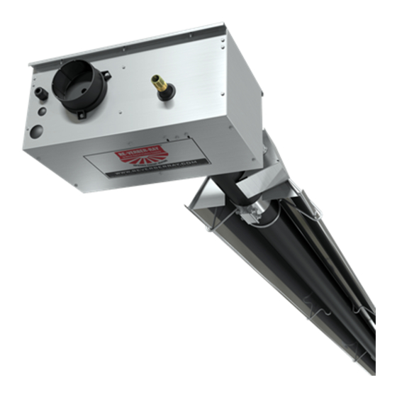
HL2 Series V.6/03 - 4" Tube Heater Installation, Operation, Maintenance and Parts Manual
WARNING:
This heater must be installed and serviced by trained gas installation and service personnel only!
!
Improper installation, adjustment, alteration, service or maintenance can cause property damage, injury or death.
Read the installation, operating and maintenance instructions thoroughly before installing or servicing this equipment.
Protect yourself and others by observing all safety information. Retain instructions for future reference.
HL2 Series
Project: _________________________ Date: _______________
Customer Name: _______________________________________
Location: _____________________________________________
City: ______________________ State: _______ Zip: __________
Contractor: ____________________________________________
Engineer: _____________________________________________
Address: _____________________________________________
City: ______________________ State: _______ Zip: _________
Serial #: _________________________ Phone#: _____________
Local Representative: ___________________________________
Date of Installation: ______________________________________
Notes: _______________________________________________
Models
V.6/03
Ga s Type
Qty.
Mode l #
(cir cle one )
HL2 20-65
N or LP
HL2 20-75
N or LP
HL2 20-100
N or LP
HL2 30-65
N or LP
HL2 30-75
N or LP
HL2 30-100
N or LP
HL2 30-125
N or LP
HL2 40-65
N or LP
HL2 40-75
N or LP
HL2 40-100
N or LP
HL2 40-125
N or LP
HL2 40-150
N or LP
HL2 40-175
N or LP
HL2 50-125
N or LP
HL2 50-150
N or LP
HL2 50-175
N or LP
HL2 50-200
N or LP
HL2 60-150
N or LP
HL2 60-175
N or LP
HL2 60-200
N or LP
HL2 70-175
N or LP
HL2 70-200
N or LP
* Model requires 5EA-SUB accessory package.
*For complete installation instructions, see the General Manual that accompanied this piece.
Additional literature on this and other products are available at www.reverberray.com.
Stra ight
U-Tube
MBTU's
Le ngth
Le ngth W e ight
65 / 50
21'-7'
13'-0"
120 #
75 / 50
21'-7'
13'-0"
120 #
96 / 65
21'-7'
13'-0"
120 #
65 / 50
31'-3'
*17'-8"
160 #
75 / 50
31'-3'
*17'-8"
160 #
100 / 65
31'-3'
*17'-8"
160 #
125 / 95
31'-3'
*17'-8"
160 #
65 / 50
40'-11'
22'-8"
190 #
75 / 50
40'-11'
22'-8"
190 #
100 / 65
40'-11'
22'-8"
190 #
125 / 95
40'-11'
22'-8"
190 #
150 / 100
40'-11'
22'-8"
190 #
175 / 125
40'-11'
22'-8"
190 #
125 / 95
50'-7'
*27'-4"
235 #
150 / 100
50'-7'
*27'-4"
235 #
175 / 125
50'-7'
*27'-4"
235 #
200 / 145
50'-7'
*27'-4"
235 #
150 / 100
60'-3'
32'-4"
265 #
175 / 125
60'-3'
32'-4"
265 #
200 / 145
60'-3'
32'-4"
265 #
175 / 125
69'-11"
*37'-2"
300 #
200 / 145
69'-11"
*37'-2"
300 #
©
2002 Detroit Radiant Products Co.
21400 Hoover Rd., Warren, MI 48089
T. (586) 756-0950 F. (586) 756-2626
Form# LIOHL2-3M-10/03 (ID)
Replaces Form# LIOHL2-3M-12/02
Typica l
Mount
Com bustion
He ight
Cha m be r
Em itte r Tube
9'-14'
Aluminized
4" Aluminized
10' - 15'
Aluminized
4" Aluminized
11' - 18'
Aluminized
4" Aluminized
10' - 15'
Aluminized
4" Aluminized
11' - 18'
Aluminized
4" Aluminized
12' - 20'
Aluminized
4" Aluminized
13' - 23'
Aluminized
4" Aluminized
11' - 18'
Aluminized
4" Aluminized
11' - 18'
Aluminized
4" Aluminized
12' - 20'
Aluminized
4" Aluminized
13' - 23'
Aluminized
4" Aluminized
14' - 25'
Titanium Coated
4" Aluminized
15' - 27'
4" Aluminized
Titanium Coated
15' - 27'
Aluminized
4" Aluminized
15' - 27'
Titanium Coated
4" Aluminized
16' - 30'
4" Aluminized
Titanium Coated
17' - 35'
Titanium Coated
4" Aluminized
16' - 30'
4" Aluminized
Titanium Coated
16' - 30'
4" Aluminized
Titanium Coated
17' - 35'
Titanium Coated
4" Aluminized
19' - 42'
4" Aluminized
Titanium Coated
19' - 42'
Titanium Coated
4" Aluminized
Warranty registration options:
1. Register online at www.reverberray.com/warranty
2. Complete this page and fax to Detroit Radiant Products Co.
3. Complete this page and mail to Detroit Radiant Products Co.
Printed in U.S.A.
*
Table of Contents
Models
Warnings
Clearances to Combustibles 2
Product Summary
Product Instructions
Heater Requirements
Theory of Operation
Wiring Diagrams
Flowchart
Parts Listing
Ra dia nt
"Type " Tube
"Type " Tube
Pkg #1
Pkg. #2
20-4 Alum
20-4 Alum
20-4 Alum
30-4 Alum
30-4 Alum
30-4 Alum
30-4 Alum
40-4 Alum
40-4 Alum
40-4 Alum
40-4 Alum
40-4 Titan
40-4 Titan
40-4 Alum
10-4 Alum
40-4 Titan
10-4 Alum
40-4 Titan
10-4 Alum
40-4 Titan
10-4 Alum
40-4 Titan
20-4 Alum
40-4 Titan
20-4 Alum
40-4 Titan
20-4 Alum
40-4 Titan
30-4 Alum
40-4 Titan
30-4 Alum
Page
1
2
3
3
4
4
5-7
8-9
10-11
Ba ffle
Pie ce s
N/A
5
N/A
5
N/A
5
N/A
4
N/A
4
N/A
5
N/A
5
N/A
2
N/A
2
N/A
4
N/A
4
N/A
4
N/A
4
4
4
2
2
2
2
2
2
2
Advertisement
Table of Contents

Related Manuals for Detroit Radiant Products HL2 Series


Summary of Contents for Detroit Radiant Products HL2 Series
- Page 1 HL2 Series V.6/03 - 4” Tube Heater Installation, Operation, Maintenance and Parts Manual WARNING: This heater must be installed and serviced by trained gas installation and service personnel only! Improper installation, adjustment, alteration, service or maintenance can cause property damage, injury or death.
- Page 2 HL2 Series V.6/03 - 4” Tube Heater Installation, Operation, Maintenance and Parts Manual HL2 Series HL2 Series Mechanical Instructions CLEARANCES TO COMBUSTIBLES (IN.) WARNING! MOUNTING SIDE MODEL NO. BELOW NOT FOR RESIDENTIAL USE! ANGLE FRONT BEHIND Do not use in the home, sleeping quarters, 0º...
-
Page 3: Product Summary
(HLRB) and installed using an external transformer (field supplied) as shown on page 6. A HL2 Series unit with a relay board (HLRB) installed is identified by the orange band around the terminal strip. -
Page 4: Electrical Requirements
HL2 Series V.6/03 - 4” Tube Heater Installation, Operation, Maintenance and Parts Manual HL2 Series First Stage Running Circuit: Electrical Requirements After ignition the flame-rod monitors the main burner flame. If flame is lost, the control acts to close the gas valve within one ♦... -
Page 5: Internal Wiring Diagrams
HL2 Series V.6/03 - 4” Tube Heater Installation, Operation, Maintenance and Parts Manual Internal Wiring Diagrams MICRO 60U-24 MICRO 60U-24 LADDER DIAGRAM 120VAC 120V TRANSFORMER IGNITOR FLAME PRESSURE SWITCH T'STAT TERMINAL APS1 BLOWER INDICATOR LIGHTS 2-STAGE T'STAT (FIELD SUPPLIED) MICRO 60U-24... -
Page 6: Field Wiring Diagrams
HL2 Series V.6/03 - 4” Tube Heater Installation, Operation, Maintenance and Parts Manual HL2 Series Field Wiring Diagrams Note: If optional yellow control cord is installed then the following wire colors apply: 24v - Green Low - White High - Black... -
Page 7: Alternative Wiring Diagrams
HL2 Series V.6/03 - 4” Tube Heater Installation, Operation, Maintenance and Parts Manual Alternative Wiring Diagrams MICRO 60U-24 WITH HLRB RELAY BOARD MICRO 60U-24 LADDER DIAGRAM - WITH RELAY BOARD 120VAC 120V HL RELAY BOARD TRANSFORMER IGNITOR FLAME PRESSURE SWITCHES... -
Page 10: Parts Breakdown
HL2 Series V.6/03 - 4” Tube Heater Installation, Operation, Maintenance and Parts Manual HL2 Series Parts Breakdown... -
Page 11: Basic Parts List
HL2 Series V.6/03 - 4” Tube Heater Installation, Operation, Maintenance and Parts Manual Basic Parts List... -
Page 12: Product Features
HL2 Series V.6/03 - 4” Tube Heater Installation, Operation, Maintenance and Parts Manual Kit Contents & Product Features Kit contents for the HL2 Series are shown below. Reference the proper column for your particular models length. FILLED BY: HL2 SERIES KIT CONTENTS...
Need help?
Do you have a question about the HL2 Series and is the answer not in the manual?
Questions and answers