Table of Contents
Advertisement
Quick Links
Detroit Radiant Products Company
DST Series
Installation Manual
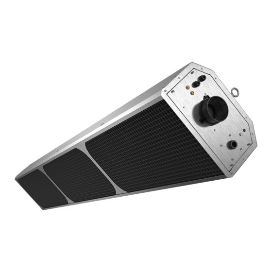
The DST Series Infrared Tube Heater is a positive pressure, two-stage radiant heater system. This
manual provides specific information related to the DST series models. All persons involved with the
installation, operation, and maintenance of the heater system must read and understand the information
in this manual.
Improper installation, adjustment, alteration, service, or maintenance can cause
property damage, injury, or death. Read the installation, operation, and maintenance
instructions thoroughly before installing or servicing this equipment.
This heater must be installed and serviced by trained gas installation and service
personnel only. Failure to comply could result in personal injury, asphyxiation, death,
fire, or property damage.
Do not store or use gasoline or other flammable vapors and liquids in the vicinity of
this or any other appliance.
In locations used for the storage of combustible materials, signs must be posted to
specify the maximum permissible stacking height to maintain the required clearances
from the heater to the combustibles. Signs must either be posted adjacent to the
heater thermostats or, in the absence of such thermostats, in a conspicuous location.
Do not use this heater in indoor living or sleeping quarters, etc.! Installation of a
tube heater system in residential indoor living spaces may result in property damage,
serious injury, asphyxiation, or death.
If you smell gas:
1. Shut off gas to the appliance.
2. Extinguish any flame.
3. If odor continues, keep away from the appliance and immediately call your gas supplier or fire
department.
INSTALLER: Present this manual to the end user.
Keep these instructions in a clean and dry place for future reference.
Model#: ___________________ Serial #: _________________________
!
WARNING
!
DANGER
!
(located on rating label)
LIODST.US-Rev. 15217
Print: LIODST-L-11/17 (DRPC)
Replaces:
Advertisement
Table of Contents

Related Manuals for Detroit Radiant Products DST-60N


Summary of Contents for Detroit Radiant Products DST-60N
-
Page 1: Installation Manual
Detroit Radiant Products Company DST Series Installation Manual The DST Series Infrared Tube Heater is a positive pressure, two-stage radiant heater system. This manual provides specific information related to the DST series models. All persons involved with the installation, operation, and maintenance of the heater system must read and understand the information in this manual. -
Page 2: Table Of Contents
Series Contents 1.0 Introduction ..............3 Overview . -
Page 3: Introduction
Refer to page 52 for a list of the kit contents for your series heater. Materials not included in the heater kit contents (e.g., screws, vent material, terminals, etc.) are the responsibility of the installer. Notify your product representative or Detroit Radiant Products of any discrepancy or missing kit contents prior to installing unit. -
Page 4: Safety Labels And Their Locations
Series Introduction • Safety Labels and Their Locations WARNING Read and understand all safety information and warnings in this manual before installation, operation, and maintenance of the radiant tube heater system. Safety Labels and Their Locations Product safety signs or labels should be replaced by the product user when they no longer are legible. Contact either your local distributor or the product manufacturer for obtaining replacement signs or labels. - Page 5 FOR INDOOR OR OUTDOOR USE AU CANADA POUR ALTITUDE DE 0 A 4500 PIEDS (0-0,370M) D’ALTITUDE VENTED OR DIRECT VENTED RADIANT HEATER MADE IN U.S.A. DETROIT RADIANT PRODUCTS COMPANY 21400 HOOVER ROAD - WARREN, MI 48089 (586) 756-0950 www.reverberray.com LOW-INTENSITY INFRARED HEATER RADIATEUR À...
-
Page 6: Safety
Series Safety • Warning Symbols • Applications Safety Read and understand all safety information and warnings in this manual prior to installation, operation, and maintenance of this tube heater. Warnings indicate a potentially hazardous situation which, if not avoided, could result in death or injury. WARNING Improper installation, adjustment, alteration, service, or maintenance can cause property damage, serious injury, or death. -
Page 7: Standards, Certifications, And Government Regulations
Series Safety • Applications • Standards, Certifications, and Government Regulations Commercial / Industrial (60,000 BTU/h Models Only) The DST-60 heater is designed and certified for use in industrial and commercial buildings such as warehouses, manufacturing plants, aircraft hangars, and vehicle maintenance shops. For maximum safety, the building must be evaluated for potential problems before installing the heater system. -
Page 8: Clearances To Combustibles
Series Safety • Clearances to Combustibles Clearances to Combustibles A critical safety factor to consider before installation is the clearances to combustibles. Clearance to combustibles is defined as the minimum distance you must have between the tube surface, or reflector, and the combustible item . - Page 9 Series Safety • Clearances to Combustibles In locations used for the storage of combustible materials, signs must be posted to specify the maximum permissible stacking height to maintain the required clearances from the heater to the combustibles. Signs must either be posted adjacent to the heater’s thermostat or in a conspicuous location. The stated clearance to combustibles represents a surface temperature of 90°F (50°C) above room temperature.
-
Page 10: Installation
Series Installation • Design Considerations and Prechecks Installation WARNING Improper installation, adjustment, alteration, service, or maintenance can cause property damage, serious injury, or death. Read and understand, the installation, operation, and maintenance instructions thoroughly before installing or servicing this equipment. Only trained, qualified gas installation and service personnel may install or service this equipment. -
Page 11: Recommended Mounting Heights And Coverages
* Factory recommended mounting heights are listed as a guideline. If infrared heaters are mounted too low or too high, they may result in discomfort or lack of heat. Detroit Radiant Products Company generally recommends observing the recommended mounting heights to optimize comfort conditions. However, certain applications such as spot heating, freeze protection, outdoor patio heating or very high ceilings may result in the heaters being mounted outside of the factory recommended mounting heights. -
Page 12: Heater Placement And Suspension
Series Installation • Heater Placement and Suspension Heater Placement and Suspension WARNING Improper suspension of the tube heater may result in collapse and being crushed. Always suspend from a permanent part of the building structure that can evenly support the total force and weight of the heater. -
Page 13: Sway Bracing For High Air Movement And Outdoor Applications
Series Installation • Sway Bracing for High Air Movement and Outdoor Applications Sway Bracing for High Air Movement and Outdoor Applications For high air movement and outdoor applications, install side restraints (Figure 3.4) to reduce side to side swaying. Side restraints should be installed so that they are angled at 45° ± 10° and should be placed at every designated suspension point. -
Page 14: General Venting Requirements
Series Installation • General Venting Requirements General Venting Requirements (60,000 BTU/h Models Only) The DST series unit heater must be vented as described here to properly direct the flue gases from the unit to the outside atmosphere. The venting can terminate vertically through the roof (up) or horizontally through a sidewall (sideways). -
Page 15: Replacing Existing Equipment
Series Installation • General Venting Requirements • Replacing Existing Equipment • The equivalent length for a 4 inch 90° elbow is 5 feet. • Avoid using more than two 90° directional changes in the venting system. • Suspend and secure all horizontal runs at points no greater than 3 feet apart. •... -
Page 16: Vertical Venting (Category I)
Series Installation • Vertical Venting (Category I) Vertical Venting (Category I) (60,000 BTU/h Models Only) An appliance that operates with a non-positive vent static pressure and with a vent gas temperature that avoids excessive condensate production in the vent is said to be ‘Category I’. The DST series heater is considered a Category I appliance if the venting system meets all of the following criteria: •... - Page 17 Series Installation • Vertical Venting (Category I) Figure 3.5 • Vertical Venting - Side View Vent Cap 24 in. Min.* Roof* Storm Collar Adjustable Roof Flashing 1 in. Minimum Clearance Duravent Type PVP Venting 1 in. Minimum Clearance Fire Stop Spacer Heater Vent Adapter Clean Out Tee Fitting...
-
Page 18: Horizontal Venting
Series Installation • Horizontal Venting Horizontal Venting (60,000 BTU/h Models Only) The DST series heater can be vented horizontally through a sidewall if the venting system meets all of the following criteria: • The vent system terminates horizontally (sideways). • The vent terminates vertically, but the length of the horizontal portion of the vent run exceeds 75% of the vertical rise length. -
Page 19: Common Venting (Category I)
Series Installation • Horizontal Venting • Common Venting (Category I) Figure 3.6 • Horizontal Venting Requirements Building** Overhang** Sidewall Heater 36 in. min.** Vent Adapter 6 in. min.** Sidewall Vent Cap (P/N: SWD-4) Wall Thimble Duravent Single Type PVP Wall Vent Venting 1/4 in. -
Page 20: Unvented Operation
Series Installation • Common Venting (Category I) • Unvented Operation Figure 3.7 • Common Vertical Venting - Side View Rooftop Vent Cap 24 in. Min.* Roof Duravent Type PVP Venting Firestop Spacer Heater Heater Dual Exhaust Assembly *Consult the NFPA ANSI Z223.1 Gas Vent Termination criteria if roof pitch exceeds 9:12. Unvented Operation WARNING This appliance must be vented in residential installations. -
Page 21: Installation Of Exhaust Hood When Not Venting Through Roof Or Sidewall
Series Installation • Unvented Operation • Installation of Exhaust Hood NOTE: Gravity or mechanical means may be used to accomplish the air displacement. Local codes may require that the mechanical exhaust system be interlocked with the electrical supply line to the heaters, enabling both to function simultaneously. •... -
Page 22: General Combustion Air Requirements
Series Installation • General Combustion Air Requirements General Combustion Air Requirements (All Models) Combustion air may be supplied to the heater by indoor or outdoor means. Follow these guidelines and all applicable codes for all models prior to installing the combustion air duct work. Local codes may vary. In the absence of local codes, refer and comply with the National Fuel Code ANSI Z223.1 (NFPA 54) latest edition. - Page 23 Series Installation • General Combustion Air Requirements Guidelines: Chart 3.2 • Limitations for Length and Size of Combustion Air Intake Duct Single Heater Intake Dual Heater Intake Air Intake Duct Size Max. Intake Length Duct Size Max. Intake Length 4 in. 20 ft.
- Page 24 Series Installation • General Combustion Air Requirements Figure 3.11 • Vertical Combustion Air Intake - Side View Exhaust Vent (from any other appliance) 3 ft. Min. (If X if less than 10 ft.) Roof Storm Collar Combustion Air Listed Intake Cap Flashing 18 in.
- Page 25 Series Installation • General Combustion Air Requirements Figure 3.12 • Outside Combustion Air Sidewall Intake - Side View Listed Wall Air Inlet Connection (Flexible boot Thimble and band clamps are recommended) 6 in. Min. 4” Pipe Combustion Air Intake Cap 1/4 in.
-
Page 26: Gas Supply Installation Instructions
Series Installation • Gas Supply Installation Instructions Gas Supply Installation Instructions The gas supply to the unit heater must be connected and tested in accordance with national, state, provincial, and local codes along with guidelines in this manual. In the United States refer to the latest edition of the ANSI Z223.1 (NFPA54) Standard. - Page 27 Series Installation • Gas Supply Installation Instructions To connect the gas: WARNING Failure to install, operate, or service this appliance in the approved manner may result in property damage, injury, or, death. Only trained, qualified gas installation and service personnel may install or service this equipment. The DST series heater is equipped to connect to the corrugated stainless steel tube (CSST) flexible gas connector (Included).
- Page 28 Series Installation • Installation of the Gas Line to the Heater Installation of the Gas Line to the Heater Install a sediment trap / drip leg in the supply line at the lowest spot prior to the gas ball valve. The trap length shall be at least three inches long.
- Page 29 Series Installation • Installation of the Gas Line to the Heater Refer to Chart 3.3 for natural gas and Chart 3.4 for propane to determine the cubic feet per hour (CFH) required for the type of gas and size of unit to be installed. To determine the proper pipe diameter, use the CFH value and the length of pipe necessary from Chart 3.5.
- Page 30 Series Installation • Gas Supply Installation Instructions Figure 3.15 • • Recommended Hardware Manual Shut Off and Sediment Trap In Canada, infrared heater shall only be Flow of Gas connected with a Type I hose connector that is (a) certified as being in compliance with Shut Off the Standard for Elastomeric Composite Hose and Hose Couplings for Conducting...
-
Page 31: Leak Testing
Series Installation • Gas Supply Installation Instructions • Leak Testing When connecting piping to the unit, the use of a thread joint compound is required. The thread compound (pipe dope) shall be resistant to the action of liquefied petroleum gas or any other chemical constituents of the gas to be conducted through the piping. -
Page 32: Electrical Requirements And Wiring Diagrams
Series Installation • Electrical Requirements and Wiring Diagrams • Internal Wiring Diagrams Electrical Requirements and Wiring Diagrams WARNING Shock hazard. Disconnect power supply before making wiring connections to prevent electrical shock and equipment damage. Any original factory wiring that requires replacement must be replaced with wiring material having a temperature rating of at least 105°... -
Page 33: Field Wiring Supply Voltage
Series Installation • Electrical Requirements Electrical Requirements WARNING Incorrect or improper wiring may result in shock, injury, or death. Field wiring to the heater must be connected and grounded in accordance with national, state, provincial, local codes, and to the guidelines in this manual. Refer to the most current revisions to the ANSI/NFPA 70 Standard. -
Page 34: Thermostat Connection
Series Installation • Field Wiring Supply Voltage • Thermostat Connection Thermostat Connection NOTE: Different thermostats operate according to their particular features. Refer to the thermostat’s specifications for details. Prior to connecting the thermostat wire to the heater, check to make sure the wires will be long enough to allow for the heater to freely expand and contract without causing undue strain on the wires or terminal. -
Page 35: Unit Start-Up (Commissioning)
Installation • Field Wiring • Unit Start-Up (Commissioning) • Pre-Start Up Checks Series Figure 3.18 • Field Wiring Diagram - Controlling multiple heaters with a single control device Starting Amp Draw: 5.2 Amps Running Amp Draw: 0.7 Amps CONTROL DEVICE TYP. -
Page 36: Verify Proper Inlet Pressure
Series Installation • Verify Proper Inlet Pressure 9 The voltage type and frequency listed on the rating label matches that of your application. 9 The unit is properly grounded as per the National Electrical Code, ANSI/NFPA 70 or Canadian Electrical code CSA C22.1 Part 1. 9 The unit is properly mounted to a permanent structure able to bear the weight of the unit. - Page 37 Series Installation • Verifying Manifold Pressure Verify maximum inlet gas supply pressure: Turn off all other gas appliances on the same supply line. Observe the pressure reading on the pressure gauge. The maximum inlet gas supply pressure for: • Natural gas is 14.0 inches W.C. •...
-
Page 38: Prior To Leaving The Job Site
Series Installation • Prior to Leaving the Job Site Figure 3.19 • Gas Valve Shown in OFF Position Manifold Pressure Port High Fire Manifold Pressure Adjustment Screw Low Fire Manifold Pressure Adjustment Screw Inlet Pressure Port On/Off Switch Prior to Leaving the Job Site Prior to leaving the job site, verify that: 9 The heater is clear of any objects that would interfere with the proper air circulation or that violate the listed clearances to combustibles. -
Page 39: Operation
Series Operation • Operating Instructions Operation WARNING This appliance does not have a pilot ignition. It is equipped with an ignition device which automatically lights the burner. Do not attempt to light the system by hand. Operating Instructions WARNING Use only your hand to turn the manual shut off. Never use tools. If the knob will not turn by hand, don’t try to repair it;... -
Page 40: Sequence Of Operation
Series Operation • Sequence of Operation • Diagnostics WARNING This heater must be installed and serviced by trained gas installation and service personnel only. Do not bypass any safety features or the heater’s built in safety mechanisms will be compromised. Sequence of Operation Standby: The ignition module (circuit board)continually checks for internal faults, circuit integrity and relay contact positioning. -
Page 41: Led Operation
Series Operation • LED Operation Shutdown Procedures Set the thermostat to the lowest setting. Turn OFF all electrical power to the appliance if service is to be performed. Turn manual shutoff knob clockwise to “OFF”. See Figure 3.17. Do not force. If the heater’s internal diagnostic LED displays any of the signals listed in Chart 4.1, addresses the indicated problem as outlined. -
Page 42: Maintenance
Series Maintenance • Routine Maintenance and Inspection Maintenance WARNING Personal injury or death may result if maintenance is not performed by properly trained gas installer or service personnel. Contact the installing distributor or place of purchase for service. Do not operate heating system if repairs are necessary. Allow heater to cool prior to servicing. -
Page 43: Maintenance Log
Series Maintenance • Routine Maintenance and Inspection • Vent pipe system: Check the outside termination and the connections at the heater. Inspect the vent exhausts for leakage, damage, fatigue, corrosion and obstructions. If dirt becomes a problem, installation of outside air intake ducts for combustion is recommended. •... -
Page 44: Troubleshooting Flowchart
Series Maintenance • Troubleshooting Flowchart Troubleshooting Flowchart Turn on control Pressure switch device for heat. is stuck. Replace Process Start Corrective faulty switch. Question Question Action Does the draft Is the pressure Does the heater have 120VAC inducer motor switch light on? at the main power connection? turn on? Find source of electrical problem. - Page 45 Series Maintenance • Troubleshooting Flowchart NOTICE Bypassing any switch is intended for testing purposes only. Do not leave switch bypassed during normal operation or the heater’s built-in safety mechanisms will be compromised. Check fuse on circuit board and Repair thermostat or Remove obstruction.
- Page 46 Series Maintenance • Troubleshooting Flowchart Continued from page 44 Is the gas supply valve Does the burner Were the gas lines purged to the heater in the ‘ON’ light? of air? position? Turn on gas Purge gas supply line. line. Do the burners light and Does the burner stay on Does the burner...
- Page 47 Series Maintenance • Troubleshooting Flowchart Continued from page 45 Check to make sure gas pressure is The heater is equipped with two safety within minimum and maximum inputs, as pressure switches. The burner switch is a indicated on the heater’s rating plate. normally open switch and the exhaust switch Is the gas pressure OK? is a normally closed switch.
-
Page 48: Heater Assembly Components
Series Maintenance • Heater Assembly Components Heater Assembly Components 260J, 260L Figure 5.1 • DST Series Exploded View 264K, 1325 264M 7008 851C 7015 7042 7003 7069 7016 7044 7021 7004 7040, 7041 3014 7024 7048 7022 7045 7009 7046 7001 7005 7026B... - Page 49 Series Maintenance • Heater Assembly Components • Chart 5.1 DST Series Parts List Part No. Description Part No. Description TP-41 1/4” - 20 Keps Nut TP-7010 Bracket - Exhaust TP-50A Glo-Bar Igniter TP-7011 Egg Crate Assembly TP-68B Lg. Strain Relief Bushing TP-7015 Fan Motor TP-205...
-
Page 50: Limited Warranty Terms And Conditions
Limited Warranty Terms and Conditions Three-Year Limited Warranty. The heaters covered in this manual are warranted by Detroit Radiant Products Company to the original user against defects in workmanship or materials under normal use for three years after date of purchase. Any part... - Page 51 Series Maintenance • Notes Notes...
-
Page 52: Kit Contents
• See page 50 for terms and conditions. • Residentially Outdoor Certified to CSA No. 7-89 • Commercial Approval © 2017 Detroit Radiant Products Co. 21400 Hoover Road • Warren, MI 48089 Phone: (586) 756-0950 Fax: (586) 756-2626 Proudly Made www.detroitradiant.com •...
Need help?
Do you have a question about the DST-60N and is the answer not in the manual?
Questions and answers