Table of Contents
Advertisement
Quick Links
LD3 Series
Installation Manual
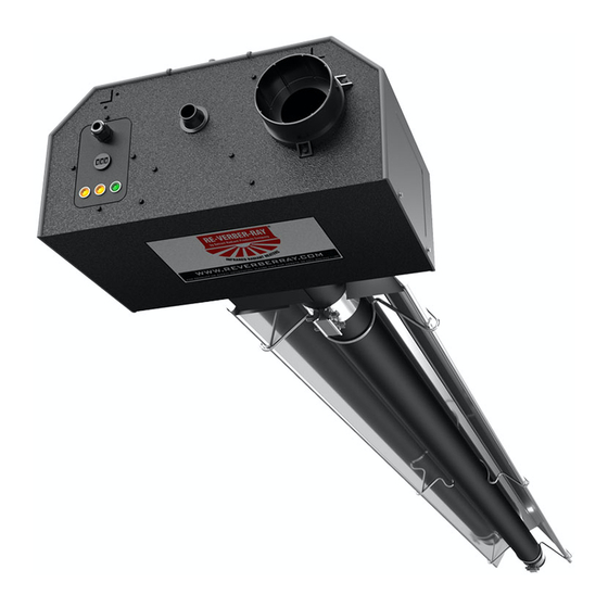
The LD3 Series Infrared Tube Heater is a positive pressure, two stage radiant tube heater system. This
manual provides specific information related to the LD3 series models. All persons involved with the
installation, operation, and maintenance of the heater system must read and understand the information
in this manual.
Improper installation, adjustment, alteration, service, or maintenance can cause
property damage, injury, or death. Read the installation, operation, and maintenance
instructions thoroughly before installing or servicing this equipment.
This heater must be installed and serviced by trained gas installation and service
personnel only. Failure to comply could result in personal injury, asphyxiation, death,
fire, or property damage.
Do not store or use gasoline or other flammable vapors and liquids in the vicinity of
this or any other appliance.
In locations used for the storage of combustible materials, signs must be posted to
specify the maximum permissible stacking height to maintain the required clearances
from the heater to the combustibles. Signs must either be posted adjacent to the
heater thermostats or, in the absence of such thermostats, in a conspicuous location.
Do not use this heater in indoor living or sleeping quarters, etc.! Installation of
a tube heater system in residential indoor living spaces may result in property damage,
serious injury, asphyxiation, or death.
For Your Safety
If you smell gas:
• Do not try to light any appliance.
• Do not touch any electrical switch.
• Do not use any phone in your building. • If you cannot reach your gas supplier, call the fire department.
INSTALLER: Present this manual to the end user.
Keep these instructions in a clean and dry place for future reference.
Model#: ___________________ Serial #: _________________________
WARNING
!
• Immediately call your gas supplier from a neighbor's phone.
• Follow the gas supplier's instructions.
(located on rating label)
LIOLD3-Rev. 31216
Print: 1c-09/18 (DRPC)
Replaces: LIOLD3-1M-12/15(CDS)
Advertisement
Table of Contents

Related Manuals for Detroit Radiant Products LD3-15-40


Summary of Contents for Detroit Radiant Products LD3-15-40
- Page 1 LD3 Series Installation Manual The LD3 Series Infrared Tube Heater is a positive pressure, two stage radiant tube heater system. This manual provides specific information related to the LD3 series models. All persons involved with the installation, operation, and maintenance of the heater system must read and understand the information in this manual.
-
Page 2: Table Of Contents
Introduction Series • Table of Contents Contents 1.0 Introduction ..............3 Overview . -
Page 3: Introduction
Reference page 60 for a list of the kit contents for your model heater. Materials not included in the heater kit contents (e.g., screws, vent material, terminals, etc.) are the responsibility of the installer. Notify your product representative or Detroit Radiant Products of any discrepancy or missing kit contents prior to installing unit. -
Page 4: Safety Signs And Labels
Series Introduction • Safety Signs and Labels WARNING Read and understand all safety information and warnings in this manual before installation, operation, and maintenance of the radiant tube heater system. Safety Signs and Labels Product safety signs or labels should be replaced by the product user when they no longer are legible. Contact either your local distributor or the product manufacturer for obtaining replacement signs or labels. - Page 5 ANSI Z21.86-2016 • CSA 2.32-2016 Service Access Service Access DETROIT RADIANT PRODUCTS COMPANY THIS HEATER REQUIRES A SPECIAL VENTING SYSTEM WHEN INSTALLED AS A CATEGORY I OR III HEATER. REFER TO THE INSTALLATION 21400 HOOVER ROAD - WARREN, MI 48089 Panel - Igniter &...
-
Page 6: Safety
Series Safety • Warning Symbols • Applications Safety Read and understand all safety information and warnings in this manual prior to installation, operation, and maintenance of this heater. Warnings indicate a potentially hazardous situation which, if not avoided, could result in injury or death. WARNING Improper installation, adjustment, alteration, service, or maintenance can cause property damage, serious injury, or death. -
Page 7: Standards, Certifications, And Government Regulations
Series Safety • Applications • Standards, Certifications and Regulations Commercial / Industrial Applications Unless otherwise indicated, tube heaters are designed and certified for use in industrial and commercial buildings such as warehouses, manufacturing plants, aircraft hangars, and vehicle maintenance shops. For maximum safety the building must be evaluated for potential problems before installing the heating system. -
Page 8: Clearances To Combustibles
Series Safety • Clearances to Combustibles Clearances to Combustibles A critical safety factor to consider before installation is the clearances to combustibles. Clearance to combustibles is defined as the minimum distance you must have between the tube surface, or reflector, and the combustible item . - Page 9 Series Safety • Clearances to Combustibles In locations used for the storage of combustible materials, signs must be posted to specify the maximum permissible stacking height to maintain the required clearances from the heater to the combustibles. Signs must either be posted adjacent to the heater’s thermostat or in a conspicuous location. The stated clearances to combustibles represent a surface temperature of 90°F (50°C) above room temperature.
-
Page 10: Installation
Installation Series • Design Considerations and Prechecks Installation WARNING Improper installation, adjustment, alteration, service, or maintenance can cause property damage, serious injury, or death. Read and understand the installation, operation, and maintenance instructions thoroughly before installing or servicing this equipment. Only trained, qualified gas installation and service personnel may install or service this equipment. -
Page 11: Recommended Mounting Heights And Coverages
Factory recommended mounting heights are listed as a guideline. If infrared heaters are mounted too low or too high, they may result in discomfort or lack of heat. Detroit Radiant Products Company generally recommends observing the recommended mounting heights to optimize comfort conditions. However, certain applications such as spot heating, freeze protection, outdoor patio heating, or very high ceilings may result in the heaters being mounted outside of the factory recommended mounting heights. -
Page 12: Hanger Placement And Suspension
Series Installation • Hanger Placement and Suspension Hanger Placement and Suspension WARNING Improper suspension of the tube heater may result in collapse and being crushed. Always suspend from a permanent part of the building structure that can evenly support the total force and weight of the heater. - Page 13 Series Installation • Hanger Placement and Suspension Figure 3.2 • Heater Mounting Layout NOTE: A sticker identifying the combustion chamber(s) is located on the Suspension swaged end of the tube(s). Point Suspension Point Suspension Point 3” O.D. Aluminized Burner Control Box Steel Radiant Emitter 3”...
- Page 14 Series Installation • Hanger Placement and Suspension Prepare mounting surface and, if necessary, weld blocks and/or drill holes (see figure 3.3). NOTE: The burner control box and radiant tubes should be in straight alignment and level. Fasten beam clamp, screw hook or other type of suspension anchor to hanging point. IF USING CHAINS: Attach and close S-hook (P/N: S-HOOK) and #1 double-loop chain (P/N: THCS) to anchor.
- Page 15 Series Installation • Hanger Placement and Suspension Figure 3.4 • U-Tube Hanger Mounting Options Single Mounting Bracket Brass Knuckle Exhaust U-Tubes can be mounted from a single suspension U-Tubes can be mounted at a 15°, 30°, or 45° angle point using an optional Single Mounting Bracket with two suspension points using two optional Brass (P/N: SMB) with five S-hooks and #1 double-loop Knuckle (P/N: BK) fittings, #1 double-loop chains,...
-
Page 16: Combustion / Radiant Tube Assembly
Series Installation • Combustion / Radiant Tube Assembly Combustion / Radiant Tube Assembly To install the combustion / radiant tubes: Place tubes in hangers with the welded seam facing downward and the swaged end of the tube towards the exhaust end of the heater system (see Figure 3.6). NOTE: The first 10 ft. combustion tube will utilize two (2) hangers and each subsequent tube will utilize one (1) hanger. -
Page 17: Optional Elbow Or U-Bend Accessory Configuration
Series Installation • Optional Elbow or U-Bend Accessory Configuration Slip-fit the radiant tube sections together until tightly connected (install the swaged end of each tube towards exhaust end). NOTE: If it is difficult to mate the tubes, they may be installed incorrectly. Center tube clamps over the seam where two radiant tube sections connect. - Page 18 Series Installation • Optional Elbow or U-Bend Accessory Configuration Figure 3.10 • Elbow and U-Bend Clearances Elbow can be set in both directions Dimension A Tube Clamp S.S. Tube Clamp U-Bend can be set in both directions Dimension A Tube Clamp 12”...
-
Page 19: Burner Control Box Suspension
Series Installation • Burner Control Box Suspension Burner Control Box Suspension Suspending the burner control box must be done in accordance with applicable codes listed in the Safety section and these instructions. The burner control box must be in straight alignment with radiant tubes and level. Contact your local distributor or the factory to see if your application allows for the rotation of the burner control box. -
Page 20: Reflector Assembly
Series Installation • Reflector Assembly Reflector Assembly Reflectors and reflector accessories direct infrared energy to the floor level. The reflector assembly depends on the heater configuration, proximity to combustibles, and space surrounding the heater. Before you begin assembly, determine if the use of reflector accessories are necessary (see Chart 3.5). To install the reflectors (see Figure 3.14): Attach the reflector center supports onto radiant tubes. - Page 21 ** Refer to the Clearances to Combustibles chart on page 9 for minimum distances to combustibles when side shield extension(s) are used. Additional accessory options are listed in the Detroit Radiant Products Company Tube Heater Accessory Guide or online at www.detroitradiant.com .
-
Page 22: Final Heater Assembly
Installation Series • Final Heater Assembly Final Heater Assembly • Chart 3.6 Tube Installation Sequence and Secured Joints for Reflectors 40,000 BTU/h Models NOTE: When securing joints on reflectors which are rotated on an angle from horizontal, secure 15 Foot joint only on top side of reflector to allow for sufficient heater expansion and contraction. -
Page 23: Venting
Series Installation • Venting • Replacing Existing Equipment Venting The LD3 series tube heater must be vented as described here to properly direct flue gases from the unit to the outside atmosphere. The venting can terminate vertically through the roof (up) or horizontally through a sidewall (sideways). - Page 24 Installation Series • General Venting Requirements WARNING CARBON MONOXIDE POISONING HAZARD Failure to follow the steps outlined below for each appliance connected to the venting system being placed into operation could result in carbon monoxide poisoning or death. The following steps shall be followed for each appliance connected to the venting system being placed into operation, while all other appliances connected to the venting system are not in operation: 1) Seal any unused opening in the venting system.
- Page 25 Series Installation • General Venting Requirements • Avoid using more than two 90° directional changes in the venting system. • Suspend and secure all horizontal runs at points no greater than 3 feet apart. • Vent termination must maintain a minimum distance of 6 feet from any mechanical air supply inlet. •...
- Page 26 Series Installation • Vertical Venting (Category I) When possible, avoid venting through an unconditioned space. Venting through an unconditioned space promotes condensation. When venting through an unconditioned space is unavoidable, or if the unit is installed in an area that is prone to condensation, insulate venting runs greater than 5 feet to minimize the production of condensation.
- Page 27 Series Installation • Horizontal Venting Figure 3.18 • Rooftop Venting - Side View Vent Cap 24 in. Min.* Roof Double-Wall B Vent Use Attic Insulation Shield (Field Supplied) Firestop Spacer Heater 3” Single-Wall Pipe B to C Adapter Clean Out Tee Fitting Clean Out Cap *Consult the NFPA ANSI Z223.1 Gas Vent Termination criteria if roof pitch exceeds 9:12.
- Page 28 Series Installation • Vent Locations and Clearances • Sidewall Venting Requirements Vent Locations and Clearances: • Horizontal venting systems may not be common vented, and no other gas units are allowed to be vented into them. • Vent must terminate a minimum of 4 feet below, 4 feet horizontally from, or 1 foot above any window or door that may be opened or gravity air inlet into the building.
- Page 29 Series Installation • • Common Venting (Category I) Common Rooftop Venting Common Venting (Category I) The common vent system and all attached appliances must be Category I. The vent connector should be routed in the most direct route from the units to the common vent. Where two or more vent connectors enter a common gas vent or chimney flue, the smaller connector shall enter at the highest level consistent with the available head room or clearance to combustible material.
-
Page 30: Combustion Air Requirements
Installation • Series Combustion Air Requirements Combustion Air Requirements Combustion air may be supplied to the heater by indoor or outdoor means. Follow these guidelines and all applicable codes for all models prior to installing the combustion air duct work. Local codes may vary. In the absence of local codes, refer and comply with the National Fuel Code ANSI Z223.1 (NFPA 54) latest edition or the National Standards of Canada. -
Page 31: Separated Combustion Systems
Series Installation • Separated Combustion Systems Separated Combustion Systems (Outside Combustion Air) All LD3 series heaters come with a factory-installed combustion air adapter for attaching air intake ducts to the heater. Attach the air intake duct material to the adapter with three (3) non-corrosive sheet metal screws. -
Page 32: Combustion Air Supply - Room Air
Installation • • Series Separated Combustion Systems Combustion Air Supply Figure 3.22 • Outside Combustion Air Vertical Intake - Side View Roof Intake Cap Roof 18 in. minimum (Flexible boot and band Air Inlet Connection 4” pipe clamps are recommended) Burner Control Box Figure 3.23... -
Page 33: Optional Unvented Operation
Series Installation • Optional Unvented Operation Optional Unvented Operation WARNING This appliance must be vented in residential installations. Unvented tube heaters in residential spaces may result in property damage, serious injury, or death. Use unvented operation in commercial and industrial installations with proper ventilation rates only. When using an unvented configuration (commercial &... -
Page 34: Gas Supply Installation Instructions
Installation Series • Gas Supply Gas Supply Installation Instructions The gas supply to the tube heater must be connected and tested in accordance with national, state, provincial, and local codes along with guidelines in this manual. In the United States refer to the latest edition of the ANSI Z223.1 (NFPA 54) Standard and in Canada refer to the latest edition of the CAN/ CGA B149.1 Standard. - Page 35 Series Installation • Gas Supply IMPORTANT! Before connecting the gas supply to the burner control box: • Verify that the heater’s gas type (as listed on the rating plate) matches that of your application and the installation complies with national and local codes and requirements of the local gas company. •...
- Page 36 Installation Series • Gas Supply Connect the main gas supply line with an approved flexible connector or, if the authority having jurisdiction requires rigid piping, the use of approved swing joints may be used. If swing joints are utilized, the heater must be allowed to freely expand and contract without causing undue stress on the gas pipe.
- Page 37 Series Installation • Gas Supply Refer to Chart 3.7 for natural gas and Chart 3.8 for propane to determine the cubic feet per hour (CFH) required for the type of gas and size of unit to be installed. To determine the proper pipe diameter, use the CFH value and the length of pipe necessary from Chart 3.9.
- Page 38 Installation Series • Leak Testing Chart 3.9 • Maximum capacity for Schedule 40 Metallic pipe, in CFH 1/2” 3/4” 1” 1-1/4” 1-1/2” 2” Pipe Length Prop Prop Prop Prop Prop Prop 10 feet 1050 1600 1046 3050 1993 20 feet 1100 2100 1373...
-
Page 39: Electrical Requirements And Wiring Diagrams
Series Installation • Electrical Requirements and Wiring Diagrams Electrical Requirements and Wiring Diagrams WARNING Shock hazard. Disconnect power supply before making wiring connections to prevent electrical shock and equipment damage. Any original factory wiring that requires replacement must be replaced with wiring material having a temperature rating of at least 105°C. -
Page 40: Typical Field Wiring
Installation Series • Field Wiring Supply Voltage • Thermostat Connection Field Wiring Supply Voltage Before proceeding with electrical connections, ensure that the supply voltage, frequency, phase, and current capacity meet the requirements specified on the rating plate. A dedicated line voltage supply with properly sized wire should run directly from the main electrical panel to the heater. - Page 41 Series Installation • Thermostat Connection The thermostat terminal designations are as follows: R: 24 VAC Power W1: Call for Heat - Low Fire W2: Call for Heat - High Fire C: Common for 24 VAC Power (if required for thermostat power) 24 VAC is supplied from an internal 40 VA transformer.
-
Page 42: Unit Start-Up (Commissioning)
Installation Series • Unit Start-up (Commissioning) • Pre-Start Up Checks Unit Start-up (Commissioning) WARNING Improper installation, adjustment, alteration, service, or maintenance can cause property damage, serious injury, or death. This heater must be installed and serviced by a trained gas installation and service personnel only. CAUTION Shock Hazard. - Page 43 Series Installation • Verify Proper Inlet Pressure Verify Proper Inlet Pressure Before starting up the unit, smell all around the heater for gas. Be sure to smell next to the floor because some gas is heavier than air and will settle on the floor. When turning the gas shut off valve, only use your hand.
- Page 44 Installation • Series Verifying Manifold Pressure Replace the inlet pressure tap plug on the gas control valve. Leak check the re-installed pressure tap plug using a soap solution or equivalent method as described in ANSI Z223.1 (NFPA 54). Figure 3.30 •...
- Page 45 Series Installation • Prior to Leaving the Job Site After five minutes, observe the pressure rating on the pressure gauge. The target manifold pressure for: • Natural gas is 3.5 inches W.C. • Propane gas is 10.0 inches W.C. NOTE: Manifold pressure of the heater is pre-set at the factory. No adjustment should be necessary.
-
Page 46: High Altitude Operation
Installation • Series High Altitude Operation High Altitude Operation WARNING Explosion hazard. This heater must be converted by a trained gas installation and service personnel only. Failure to comply could result in personal injury, asphyxiation, death, fire, or property damage. High altitude operation of this tube heater is approved, without modification, for elevations up to 6,000 feet (1,829 m) above MSL (sea level) in the United States. -
Page 47: Operation
Series Operation • Operating Instructions Operation WARNING This appliance does not have a pilot ignition. It is equipped with an ignition device which automatically lights the burner. Do not attempt to light the system by hand. BEFORE OPERATING, smell all around the appliance area for gas. Be sure to smell next to the floor because some gas is heavier than air and will settle to the floor. -
Page 48: Sequence Of Operation
Operation Series • Sequence of Operation WARNING This heater must be installed and serviced by trained gas installation and service personnel only. Do not bypass any safety features or the heater’s built in safety mechanisms will be compromised. Sequence of Operation Standby: The ignition module (circuit board) continually checks for internal faults, circuit integrity and relay contact positioning. - Page 49 Series Operation • Diagnostics Figure 4.1 • Operational Indicator Lights Light 1 Light 2 Light 3 Indicates Low Fire Indicates High Fire Indicates Pressure Operation Operation Switch are Closed Operational Indicator Lights Chart 4.1 • LED Diagnostic Codes - Capable Controls Board LED CODE FAULT STATUS FAULT CODE DELAY*...
-
Page 50: Maintenance
Series Maintenance • Troubleshooting Guide Maintenance Turn on control Pressure switch device for heat. is stuck. Replace Start Process Corrective faulty switch. Question Question Action Does the draft Is the pressure Does the heater have 120 VAC inducer motor switch light on? at the main power connection? turn on? Find source of electrical problem. - Page 51 Series Maintenance • Troubleshooting Guide NOTICE Bypassing any switch is intended for testing purposes only. Do not leave switch bypassed during normal operation or the heater’s built-in safety mechanisms will be compromised. Check internal controls Repair thermostat or Remove obstruction. transformer.
- Page 52 Series Maintenance • Troubleshooting Guide Continued from page 50 Is the gas supply valve Does the burner Were the gas lines purged to the heater in the ‘ON’ light? of air? position? Turn on gas Purge gas supply line. line. Do the burners light and Does the burner stay on Does the burner...
- Page 53 Series Maintenance • Troubleshooting Guide Continued from page 51 Check to make sure gas pressure is The heater is equipped with two safety within minimum and maximum inputs, as pressure switches. The burner switch is a indicated on the heater’s rating plate. normally open switch and the exhaust switch Is the gas pressure OK? is a normally closed switch.
-
Page 54: Heater Components And Parts List
Maintenance • Series Heater Components and Parts List Figure 5.1 • Burner Assembly Components 3097A 3098A 3011 3067 3002A 3096A 1013 222A 3012 3044 3094A 1021 3050 3140, 3141 3099A 3094A 3001B 3023 3008 3005A 3380 3062, 3063 851C See Chart 5.1 3093 3252 1070A... - Page 55 Series Maintenance • Heater Components and Parts List Chart 5.1 • Tube & Reflector Components Part No. Description Part No. Description TP-5 Flange Gasket TP-828 Yellow Indicator Light, 24 VAC TP-9C 3/4” Conduit Coupling TP-851C Ignition Control Circuit Board TP-10C 4”...
-
Page 56: Routine Inspection
Maintenance • Series Routine Inspection WARNING Personal injury or death may result if maintenance is not performed by properly trained gas installer or service personnel. Contact the installing distributor or place of purchase for service. Do not operate heating system if repairs are necessary. Allow heater to cool prior to servicing. - Page 57 Series Maintenance • Maintenance Log Reflectors: To maintain effective infrared heating, always keep both sides of the reflector clean. • Maintenance can vary significantly depending on the environment. Dirt and dust can be vacuumed or wiped with a soap and water solution. Use metal polish if the reflectors are severely dirty. Contact service personnel if repairs are necessary.
-
Page 58: Limited Warranty
Prompt Disposition. Detroit Radiant Products Company will make a good faith effort for prompt correction or other adjustment with respect to any product which proves to be defective within limited warranty. For any product believed to be defective within limited warranty, first write or call dealer from whom the product was purchased. - Page 59 Series Maintenance Notes...
-
Page 60: Kit Contents
• See page 58 for terms and conditions Certified to CSA No. 7-89 • Outdoor approval with OD-Kit • Commercial approval © 2018 Detroit Radiant Products Co. 21400 Hoover Road • Warren, MI 48089 Phone: (586) 756-0950 Fax: (586) 756-2626 www.detroitradiant.com • sales@drp-co.com...
Need help?
Do you have a question about the LD3-15-40 and is the answer not in the manual?
Questions and answers