Detroit Radiant Products EDX Series Installation, Operation, Maintenance And Parts Manual
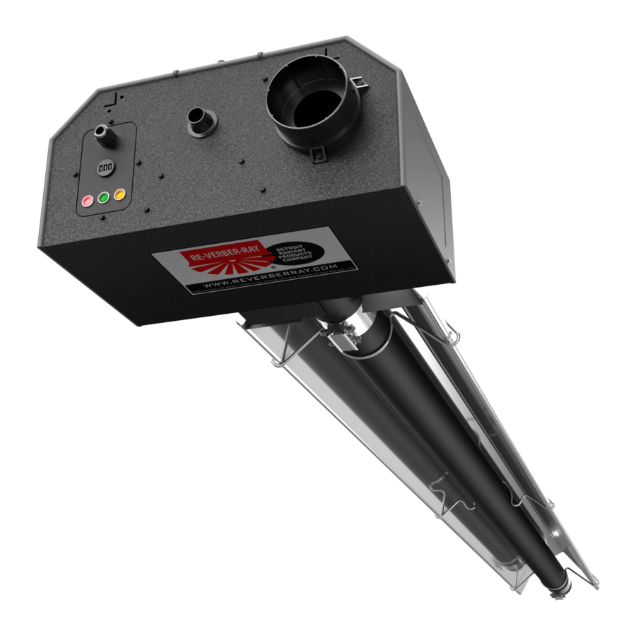
Overhead radiant gas fired infrared tube heater
Hide thumbs
Also See for EDX Series:
Table of Contents
Advertisement
Quick Links
EHL/EDX Series
AU Installation, Operation,
Maintenance and Parts Manual
AGA XXXXG Certified 240V-50Hz. Overhead Radiant Gas Fired Infrared Tube Heater.
All persons involved with the installation, operation and maintenance of the heater system must read and
understand the information in this manual.
Improper installation, adjustment, alteration, service or maintenance can cause
property damage, injury or death. Read the installation, operation and maintenance
instructions thoroughly before installing or servicing this equipment.
This heater must be installed and serviced by authorized gas installation and service
personnel only. Failure to comply could result in personal injury, asphyxiation, death,
fire or property damage.
In locations used for the storage of combustible materials, signs must be posted to
specify the maximum permissible stacking height to maintain the required clearances
from the heater to the combustibles. Signs must either be posted adjacent to the
heater thermostats or in the absence of such thermostats, in a conspicuous location.
Do not place articles on or against this appliance.
Do not use or store flammable materials near this appliance.
Do not spray aerosol in the vicinity of this appliance while in operation.
Not for residential use! Do not use this heater in the home, sleeping quarters,
attached garages, etc. Installation of a commercial tube heater system in residential
indoor spaces may result in property damage, serious injury, asphyxiation or death.
For Your Safety
If you smell gas:
• Do not try to light any appliance.
• Do not touch any electrical switch.
• Do not use any phone in your building. • If you cannot reach your gas supplier, call the fire department.
© 2007-2014 Detroit Radiant Products Co.
21400 Hoover Road • Warren, MI 48089
Phone: (586) 756-0950 Fax: (586) 756-2626
www.detroitradiant.com • sales@drp-co.com
!
WARNING
!
• Immediately call your gas supplier from a neighbor's phone.
• Follow the gas supplier's instructions.
Keep these instructions for future reference.
LIOEAU-7/07_r12/14 (DRP)
Advertisement
Table of Contents
Troubleshooting

Related Manuals for Detroit Radiant Products EDX Series


Summary of Contents for Detroit Radiant Products EDX Series
- Page 1 • Do not use any phone in your building. • If you cannot reach your gas supplier, call the fire department. Keep these instructions for future reference. © 2007-2014 Detroit Radiant Products Co. 21400 Hoover Road • Warren, MI 48089 Phone: (586) 756-0950 Fax: (586) 756-2626 www.detroitradiant.com •...
-
Page 2: Table Of Contents
Reflector Assembly ..........................21 Baffle Assembly and Placement .......................23 Final Heater Assembly ........................24 3.10 Flueing ...............................25 3.11 Combustion Air Requirements ......................30 3.12 Gas Supply ............................32 EDX SERIES SPECIFIC ...........................35 Electrical Requirements ........................35 Operation ............................37 Troubleshooting ..........................39 Replacement Parts List ........................40 Technical Specifications ........................42 EHL SERIES SPECIFIC ...........................43... - Page 3 Installation, Operation, Maintenance and Parts Manual Available Models EDX Series Offering MJ/h Length (mm) Model Length (M) Combustion Radiant Number Install Kit Chamber Tubes High Min. Max. Aluminized or EDX-50 52,8 6.705 12.473 Aluminized Hot-Rolled Steel 20 kit 30 kit...
-
Page 4: Introduction
End Caps Clips Unit Length Part No. Description Kit Size TP-19B Hanger w/ Tension Spring TP-19E* Elongated Agricultural Hanger TP-21B Tube Clamp TP-82 Reflector Center Support TP-105 Reflector End Cap TP-106 Reflector End Cap Clips LIOEAU EHL/EDX Series IOM Filled By: *Optional... -
Page 5: Safety
Safety - Installation, Operation, Maintenance and Parts Manual 2.0 Safety WARNING Improper installation, adjustment, alteration, service or maintenance can cause property damage, serious injury or death. Read and understand, the installation, operating and maintenance instructions thoroughly before installing or servicing this equipment. Only trained, authorized gas installation and service personnel may install or service this equipment. -
Page 6: Codes And Regulations
Safety - Installation, Operation, Maintenance and Parts Manual 2.3 Codes and Regulations The following must be reviewed before installing this heater: Installation must be in accordance with these instructions, local gas fitting instructions, municipal building codes, electric wiring regulations, AS 5601, and any other relevant statutory regulations. The requirements of the local authority - gas, electricity, etc. -
Page 7: Clearance To Combustibles
Safety - Installation, Operation, Maintenance and Parts Manual 2.4 Clearance to Combustibles WARNING WARNING This is not an explosion-proof Fire Hazard. Always maintain heater. Do not store or use published clearance to flammable objects, liquids or vapor combustibles. Failure to comply in the vicinity of the heater. - Page 8 For the safe installation of this unit, the clearance to combustibles data below contains clearances that must be maintained. Check the rating plate on the heater to verify the minimum clearance to combustibles and gas type for your model heater. EHL/EDX Series Clearance to Combustibles Data (mm) 0° Mounting Side Mounting...
-
Page 9: Installation
Installation - Installation, Operation, Maintenance and Parts Manual 3.0 Installation 3.1 Design Considerations and Prechecks Placement of infra-red tube heaters is influenced To ensure a properly designed heating system, a by many factors. Aside from safety factors, heating layout should be developed for the correct considerations such as the number of elbows that placement of the burner control box, radiant are allowed, maximum flue lengths and ducting of... - Page 10 Installation - Installation, Operation, Maintenance and Parts Manual General Design Scenario A tube heater system is being installed in a 27.4m (L) x 15.2m (W) space with 4.3m ceilings. Two overhead doors are located at one end and an equipment storage area exists on one side. The calculated heat load is 316.5 MJ/h.
- Page 11 Installation - Installation, Operation, Maintenance and Parts Manual Agricultural (Brood) Design Scenario Figure 3.3 - Center House Installation 76.2 m 4.6m 4.6m 5.8m 5.5m 5.8m 9.1m 12.5m 12.5m 12.5m 12.5m NOTE: Utilize CH hangers on houses 18.3 meters or more with center house mounting. Figure 3.4 - Side Wall Installation 76.2m-152.4m 2.8m...
-
Page 12: Recommended Mounting Heights
Installation - Installation, Operation, Maintenance and Parts Manual Design Criteria 3.2 Recommended Mounting Heights (Industrial/Commerical Applications) EDX/ 53-63 14.6 - 17.6 3.5 - 5.0 6.5 x 4.0 4.0 x 4.0 3.5 - 6.5 6.5 - 12.5 EHL 6M 22.0 - 29.3 4.0 - 6.5 7.0 x 4.5 4.0 x 4.5... -
Page 13: Hanger Placement And Suspension
Installation - Installation, Operation, Maintenance and Parts Manual 3.3 Hanger Placement and Suspension WARNING Improper suspension of the heater may result in collapse and being crushed. Always suspend the appliance from a permanent part of the building structure that can support the total weight and force of the heater. - Page 14 Installation - Installation, Operation, Maintenance and Parts Manual Hanger Placement and Suspension Suspension Point Heater Suspension Layout Figure 3.7 • Note: A sticker identifying the combustion chamber(s) is located on the swaged end of the tube(s). Suspension Point Radiant Emitter Tube(s) Suspension Point...
- Page 15 Installation - Installation, Operation, Maintenance and Parts Manual Hanger Placement and Suspension Suspension of the heater must conform to applicable codes referenced in the Safety section and these instructions. Prepare the mounting surface. If necessary, weld blocks, drill holes, etc. Figure 3.8. NOTE: The burner control box and radiant tubes should be in straight alignment and level.
-
Page 16: Optional U-Bend Or Elbow Accessory Configuration
Installation - Installation, Operation, Maintenance and Parts Manual 3.4 Optional U-Bend or Elbow Accessory Configuration Figure 3.9 • U-Tube Hanger Mounting Options Single Mounting Bracket Brass Knuckle Exhaust U-Tubes can be mounted from a single suspension U-Tubes can be mounted at a point using a Single Mounting Bracket (P/N: SMB) 15, 30 or 45 degree angle with two with five S-hooks and double-loop chains. -
Page 17: Radiant Tube Assembly
Installation - Installation, Operation, Maintenance and Parts Manual 3.5 Radiant Tube Assembly To install the radiant tubes: Place tubes in hangers with the welded seam facing downward and the swaged end of the tube towards the exhaust end of the heater system (see Figure 3.11). Refer to Section 3.9 on page 24 for tube installation sequence. - Page 18 Installation - Installation, Operation, Maintenance and Parts Manual Radiant Tube Assembly 3 Slip-fit the radiant tube sections together until tightly connected (install swaged end of each tube towards exhaust end). NOTE: If it is difficult to mate the tubes, they may be installed incorrectly. 4 Center tube clamps over the seams where two radiant tube sections connect.
- Page 19 Installation - Installation, Operation, Maintenance and Parts Manual Radiant Tube Assembly Elbow can be set Figure 3.15 • Elbow and U-Bend Clearances in both directions Dimension A Tube Clamp Tube Clamp U-Bend can be set in both directions Dimension A 305mm Tube Clamp Tube Clamp...
-
Page 20: Burner Control Box Suspension
Installation - Installation, Operation, Maintenance and Parts Manual 3.6 Burner Control Box Suspension Suspending the burner control box must be done in accordance with applicable codes listed in the Safety section and these instructions. The burner control box must be in straight alignment with the radiant tubes and level. Determine the mounting chain locations for hanging the burner control box. -
Page 21: Reflector Assembly
Installation - Installation, Operation, Maintenance and Parts Manual 3.7 Reflector Assembly To install the reflectors: Attach reflector center supports onto radiant tubes. Slide each reflector section through the hangers and adjust the reflector tension spring into the V-groove on the top of the reflector. The reflectors should overlap approximately 102mm. To prevent the reflectors from shifting, secure the reflector sections together using sheet metal screws except at the expansion joint (see page 24). - Page 22 Installation - Installation, Operation, Maintenance and Parts Manual Reflector Assembly Common Optional Accessories Reflector Accessories Description Part # Elbow Reflector* 90° bend, highly polished aluminum reflector elbow. Designed to fit atop one elbow accessory fitting. U-Reflector* 180° bend, highly polished aluminum reflector U-bend. Designed to fit atop one U-bend accessoy fitting.
-
Page 23: Baffle Assembly And Placement
Installation - Installation, Operation, Maintenance and Parts Manual 3.8 Baffle Assembly and Placement To assemble the baffles: Note: Baffles may be inserted into the tube while being assembled. Determine the number of baffles needed for your model number. Remove one 840mm baffle section if heater is installed with an elbow or U-bend accessory. -
Page 24: Final Heater Assembly
Installation - Installation, Operation, Maintenance and Parts Manual 3.9 Final Heater Assembly NOTICE Different inputs and models utilize different baffle lengths. Remove all enclosed baffle sections from box and retain with applicable heater. Reference shipping label for proper baffle size. Each 840mm baffle section must be assembled with other baffles and placed in the radiant tube section furthest Burner Control Box... -
Page 25: Flueing
Installation - Installation, Operation, Maintenance and Parts Manual 3.10 Flueing WARNING Insufficient ventilation and/or improperly sealed flues may release gas into the building which could result in health problems, carbon monoxide poisoning or death. Improper flueing may result in fire, explosion, injury or death. Seal flue pipes with high temperature sealant and three (3) sheet metal screws. - Page 26 Installation - Installation, Operation, Maintenance and Parts Manual Flue Assembly Figure 3.24 • General Flue Requirements Flue Cap 610 mm Min. Roof Storm Collar Adjustable Roof Flashing 26 mm. minimum clearance Twin Skin Flue 26 mm. minimum clearance Ceiling ring Spacer Heater Twin Skin to Single Skin Adapter Single Skin Elbow or Alternate Tee Fitting...
- Page 27 Installation - Installation, Operation, Maintenance and Parts Manual Flue Assembly Flue Termination • Flue must terminate a minimum of 1200mm below, 1200mm horizontally from and 300mm above any window or door that may be opened and gravity air inlet into the building. •...
-
Page 28: Flue Requirements
Installation - Installation, Operation, Maintenance and Parts Manual Flue Requirements Figure 3.26 • Sidewall Flueing - Top View Sidewall B To C Heater Adapter 150 mm. min. Sidewall Flue Cap Wall Thimble Double-wall B-Vent Single Skin Flue Rooftop Flueing Guidelines: •... - Page 29 Installation - Installation, Operation, Maintenance and Parts Manual Optional Unflued Operation WARNING Not for residential use. The use of unflued tube heaters in residential indoor spaces may result in property damage, serious injury or death. Use unflued operation in commercial and industrial installations with proper ventilation rates only.
-
Page 30: Combustion Air Requirements
Installation - Installation, Operation, Maintenance and Parts Manual 3.11 Combustion Air Requirements NOTICE This heater has a factory preset air orifice for proper combustion air supply. If combustion air is to be provided for a tightly closed area, 123 ccm of free air opening must be provided for per mj/h of heater input. Non-contaminated air for combustion must be ducted to the heater if chlorinated or fluorinated contaminants, high humidity and other contaminants such as sawdust or welding smoke are present in the area where the heater is installed, or if the building has a negative pressure. - Page 31 Installation - Installation, Operation, Maintenance and Parts Manual Combustion Air Requirements Guidelines: Limitations for length and size of combustion air intake duct Single Heater Intake Dual Heater Intake Air Intake Duct Size Max. Intake Length Duct Size Max. Intake Length 100mm 6100mm 100mm.(single)/150in.(dual)
-
Page 32: Gas Supply
Installation - Installation, Operation, Maintenance and Parts Manual 3.12 Gas Supply WARNING Improperly connected gas lines may result in fire, explosion, poisonous fumes, toxic gases, asphyxiation or death. Connect gas lines in accordance to national, state, provincial and local codes. Important! Before connecting the gas supply to the burner control box: •... -
Page 33: Gas Connection
Installation - Installation, Operation, Maintenance and Parts Manual Gas Connection WARNING Failure to install, operate or service this appliance in the approved manner may result in property damage, injury or death. Only trained, authorized gas installation and service personnel may install or service this equipment. To connect the gas: This heater must be installed and service by trained gas installation and service personnel only. - Page 34 Installation - Installation, Operation, Maintenance and Parts Manual Gas Supply WARNING Testing for gas leaks with an open flame or other sources of ignition may lead to a fire or explosion and cause serious injury or death. Test in accordance with AS 5601 or other relevant codes of practice.
-
Page 35: Edx Series Specific
EDX Series Specifc - Installation, Operation, Maintenance and Parts Manual 4.0 EDX Series Specific EDX Series Electrical Requirements • Verify that the heater’s voltage (as listed on the rating plate) matches that of your application. • Heaters operate on 230 volts, 50Hz., single phase. The amperage requirement is 0.6 Amps running current per heater. - Page 36 EDX Series Specific - Installation, Operation, Maintenance and Parts Manual EDX Series Internal Wiring Diagram If any of the original wire as supplied with this appliance must be replaced, it must be replaced with wiring material having a temperature rating of at least 105°C.
-
Page 37: Operation
EDX Series Specific - Installation, Operation, Maintenance and Parts Manual 4.2 EDX Series Operation WARNING This heater is not equipped with a pilot ignition system. Do not attempt to light the system manually. EDX Series Commissioning Procedures: Ensure that ball valve to the heater is turned “OFF”. - Page 38 EDX Series Specific - Installation, Operation, Maintenance and Parts Manual EDX Series Sequence of Operation Starting Circuit The blower fan is mounted in the control box and rated to supply sufficient air for combustion. Air pressure generated by the blower will cause the differential switch to close. The system is purged for 10 seconds and the control module sends a spark through the electrode.
-
Page 39: Troubleshooting
EDX Series Specific - Installation, Operation, Maintenance and Parts Manual 4.3 EDX Series Troubleshooting Guide Chart 4.1 EDX Troubleshooting Guide Symptom Possible Cause Corrective Action Thermostat closed, fan doesn’t • Blown fuse. • Replace. operate. • Faulty thermostat. • Replace. -
Page 40: Replacement Parts List
EDX Series Specific - Installation, Operation, Maintenance and Parts Manual 4.4 EDX Series Parts Figure 4.1 EDX Series Burner Assembly Components 664D,E,F 651A 383B 628A,B 635A 740A 200A,201B 208B Chart 4.1 • EDX Series Parts List Part # Description TP-1... - Page 41 EDX Series Specific - Installation, Operation, Maintenance and Parts Manual EDX Series Basic Parts List Figure 4.2 EDX Series Tube & Reflector Components 26A, 26D 20C,D 21B, 220 26A,B,C,E Part # Description TP-208B Gas Valve Mounting Bracket TP-554 Ignitor Mounting Bracket Gasket...
-
Page 42: Technical Specifications
EDX Series Technical Specifications - Installation, Operation, Maintenance and Parts Manual 4.5 EDX Series Technical Specifications... -
Page 43: Ehl Series Specific
EHL Series Specifc - Installation, Operation, Maintenance and Parts Manual 5.0 EHL Series Specific 5.1 EHL Series Electrical Requirements • Verify that the heater’s voltage (as listed on the rating plate) matches that of your application. • Heaters operate on 230 volts, 50Hz., single phase. The amperage requirement is 0.6 Amps running current per heater. - Page 44 EHL Series Specific - Installation, Operation, Maintenance and Parts Manual EHL Series Field Wiring Diagrams If any of the original wire as supplied with this appliance must be replaced, it must be replaced with wiring material having a temperature rating of at least 105°C. Figure 5.2 - EHL Series Internal Wiring Diagram Ignitor/ Sensor...
-
Page 45: Operation
EHL Series Specific - Installation, Operation, Maintenance and Parts Manual 5.2 EHL Series Operation WARNING This heater is not equipped with a pilot ignition system. Do not attempt to light the system manually. EHL Series Commissioning Procedures: Ensure that ball valve to the heater is turned “OFF”. Purge air from the gas supply line and test for gas soundness in accordance with relevant Standards. - Page 46 EHL Series Specific - Installation, Operation, Maintenance and Parts Manual EHL Series Sequence of Operation Starting Circuit The blower fan is mounted in the control box and rated to supply sufficient air for combustion. Air pressure generated by the blower will cause the differential switch to close. The system is purged for 10 seconds and the control module sends a spark through the electrode.
-
Page 47: Troubleshooting
EHL Series Specific- Installation, Operation, Maintenance and Parts Manual 5.3 EHL Series Troubleshooting Guide Chart 5.1 EHL Troubleshooting Guide Symptom Possible Cause Corrective Action Thermostat closed, fan doesn’t • Blown fuse. • Replace. operate. • Faulty thermostat. • Replace. • Loose or disconnected wire. •... -
Page 48: Replacement Parts List
EHL Series Specific - Installation, Operation, Maintenance and Parts Manual 5.4 EHL Series Parts 5.2 EHL Series Burner Assembly Components 664D,E,F 651A 383B 628A,B,C 635A 646A 640A 200A,201B 208B Chart 5.2 • EHL Series Parts List Part # Description TP-1 Control Box Cover TP-33B Ball Valve Shut-off... - Page 49 EHL Series Specific - Installation, Operation, Maintenance and Parts Manual EHL Series Basic Parts List 5.3 EHL Series Tube & Reflector Components 26A, 26D 20C,D 21B, 220 26A,B,C,E Part # Description TP-208B Gas Valve Mounting Bracket TP-555 Spark Ignitor Electrode TP-212 Gas Valve Pipe Nipple TP-580...
-
Page 50: Technical Specifications
EHL Series Specific - Installation, Operation, Maintenance and Parts Manual 5.5 EHL Series Technical Specifications... -
Page 51: Maintenance
• Check integrity of the electrode. If damaged, it must be replaced complete with holder. Maintenance Log Date Maintenance Period Replacement Parts Required Replacement parts can be purchased from your local dealer. Contact Detroit Radiant Products at 011-586-756-0950 or store.reverberray.com... - Page 52 © 2007 Detroit Radiant Products Co. 21400 Hoover Road • Warren, MI 48089 Phone: (586) 756-0950 Fax: (586) 756-2626 www.detroitradiant.com • sales@detroitradiant.com Printed in U. S. A.
Need help?
Do you have a question about the EDX Series and is the answer not in the manual?
Questions and answers