Table of Contents
Advertisement
Quick Links
Advertisement
Table of Contents

Related Manuals for Seneca MyBoat-WR


Summary of Contents for Seneca MyBoat-WR
- Page 1 User Manual...
- Page 2 ACTIVATION CODE...
-
Page 5: Table Of Contents
TABLE OF CONTENTS WARNINGS P.06 PRODUCT DESCRIPTION P.07 PACKET CONTENT P.10 CONTROL UNIT OPERATION P.11 SENSOR DESCRIPTION P.12 APP HOME SCREEN P.13 MYBOAT APP DESCRIPTION P.14 CONTROL UNIT INSTALLATION P.22 SENSOR INSTALLATION P.24 CLOUD SERVICE ACTIVATION P.28 TROUBLESHOOTING P.32... -
Page 6: Warnings
• Do not apply different voltages or higher voltages than indicated between terminals, or between any terminal and earth (voltages greater than 50Vdc) • Do not use the MyBoat-WR control unit if damaged, or if signs of possible damage are visible on it. -
Page 7: Product Description
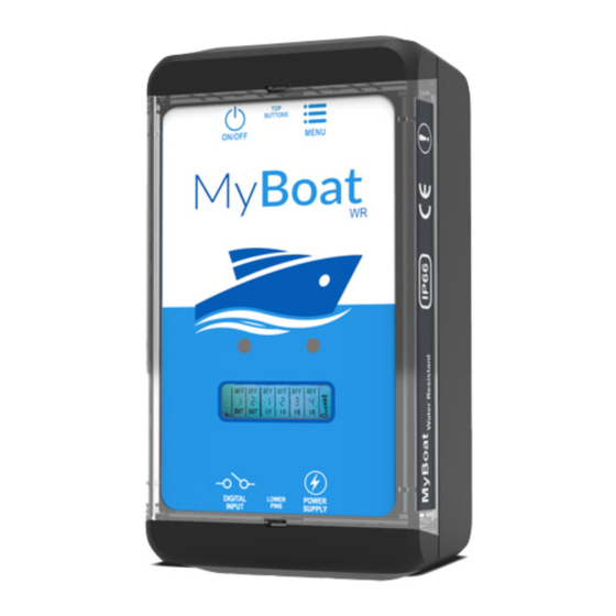
SMS service ASSEMBLY REGULATIONS For optimum reception of the GPS signal given by satel- lites, it is better to place the MyBoat-WR horizontally on a surface in an area not covered by metal structures. SYMBOLS ON THE ENCLOSURE ON / OFF power button... - Page 8 Lithium Ion 3.7 V -1000 mAh, rechargeable Internal batteries Ambient conditions Seneca recommends use at 0 to 45°C for correct operation With the power supply present: -20 .. +55°C Temperature With use of the battery (when discharged): -20 .. 45°C. Charging is possible in the range: 0 ..
- Page 9 2 - PRODUCT DESCRIPTION MyBoat control The MyBoat control unit is a SENECA industrial-style unit product . Remote (MyAlarm2) alarm, telemetry and data- logging industrial unit. Technical characteristics: • Display LCD 128 x 32 Dots • Rechargeable Li-Io buff- er battery, up to 8 hours’...
-
Page 10: Packet Content
3 - PACKET CONTENT 1 - MyBoat control unit (I1) 2 - Battery state sensor (I2) 3 - Motor state and locker state sensor (I2) 4 - User Manual 5 - Power supply unit 12 V 6 - Power cable with fork for coupling with the battery 7 - Velcro to fix the control unit 8 - SD card for firmware updates 9 - V-SIM card by Vodafone worldwide... -
Page 11: Control Unit Operation
4 - CONTROL UNIT OPERATION Connection to the Seneca Cloud system BUTTONS ON/OFF MENU Internal GPS antenna Cable for power supply on 230 V socket DIGITAL LOWER POWER PINS INPUT SUPPLY Accessory included Power cable and battery sensor IPX8 terminal... -
Page 12: Sensor Description
The sensors are devices connected to the digital inputs of the MyBoat-WR control unit. Using the MyBoat By SENECA app, you can monitor the status of the service batteries of your boat, the possible opening of the locker compartment and the presence of the engine. -
Page 13: App Home Screen
6 - APP HOME SCREEN Monitoring system status Service battery status Motor status Locker status Quay connection status Notification area NOTIFICATION AREA The following is displayed in the notification area (6): • the name of the boat being monitored; • the status of the boat in comparison with the virtual compound;... -
Page 14: Myboat App Description
7 - MYBOAT APP DESCRIPTION Monitoring system status Perimeter alarm status Battery voltage status Alarm activation but- Alarm deactivation button MyBoat MI005220-E... - Page 15 7 - MyBoat APP DESCRIPTION Indication of No. of messages Page management Message preview HISTORY FUNCTION The history function allows display- ing and filing the alarm messages sent by the MyBoat system to have a constant record of the events and of the individual actions and/or com- mands of all the users.
- Page 16 7 - MyBoat APP DESCRIPTION Close page Configuration of the notifications General parameters Commands for SMS notifications SMS address book settings Checks the on-board system status Information on the account cloud Privacy settings Licence terms To view these settings, activate them in the general parameters section.
- Page 17 7 - MyBoat APP DESCRIPTION Name of the boat SMS sending setup Changes the icon dimensions Language settings Saves the modifications Cancels the modifications MyBoat MI005220-E...
- Page 18 7 - MyBoat APP DESCRIPTION Close the page Boat 1 Boat 2 Add boat Cancel the operation GENERAL SETTINGS For the management of multiple boats (fleet), the general settings are saved on your smartphone locally and must be customized for a single one-off vessel.
- Page 19 7 - MyBoat APP DESCRIPTION Close the page Device information MyBoat MI005220-E...
- Page 20 7 - MyBoat APP DESCRIPTION Cloud service in- formation Cloud service mainte- nance MyBoat MI005220-E...
- Page 21 7 - MyBoat APP DESCRIPTION Localization screen Saves position Road directions Share position Download position SHARE POSITION The “share position” function allows sending the position of the boat viewed. MyBoat MI005220-E...
-
Page 22: Control Unit Installation
2. Insert the micro SD Switching on and menu card into the MyBoat keys: _WR control unit; MyBoat-WR is fitted with an 3. Power the control unit ON/OFF PWR key positioned via the supplied 12 V in the LH top corner (Figure power supply 4. - Page 23 8 - CONTROL UNIT INSTALLATION N.B. In order to guarantee (*) if a SIM card other than the one supplied with the the MyBoat_WR control KIT is used, ensure you unit works correctly, THE have removed the locking CONTENT OF THE SD CARD PIN when you switched on MUST NOT BE REMOVED.
-
Page 24: Sensor Installation
9 - SENSOR INSTALLATION Useful for checking the status of the service battery and possible connection to the power supply via the quay. Monitoring the status of the service battery takes place via the MyBoat control unit and its power supply connector. - Page 25 9 - SENSOR INSTALLATION 1. Connect the cable with the 8mm forks to the battery terminals, pay- ing attention to polarity as shown in the side figure. 2. Connect the cable to the control unit, taking care to insert it into the dedi- cated socket identifiable by the "POWER SUPPLY"...
- Page 26 9 - SENSOR INSTALLATION 1. Identify the installation point of both the sensor (e.g. locker frame) and the magnet (e.g. locker flap) and clean the two areas identified; 2. To guarantee it works properly, leave a maxi- mum distance of 10 mm between the two ele- ments when installing.
- Page 27 9 - SENSOR INSTALLATION 1. Uncouple the cable from the connection termi- nal at the base of the sensor; 2. Position the cable so that it is secured to the engine of your boat; 3. Recouple the cable to the connection termi- nal;...
-
Page 28: Cloud Service Activation
10 - CLOUD SERVICE ACTIVATION To use the MyBoat monitoring system, it is necessary to register a SENECA Cloud account and activate the dedicat- ed service. KIT includes a usage fee for 24 months TheMyBoat from first activation. For further information and renewal costs go to: www.seneca.it/myboat_wr... - Page 29 Activation via MyBoat app 1. Start the control unit as per first startup procedure (see page 24) 2. Install the MyBoat by Seneca app available in the iOS and Android stores, using the following QR codes or searching for MyBoat by SENECA: MyBoat 3.
- Page 30 10 - CLOUD SERVICE ACTIVATION Creating new users: Creating new users for MyBoat service is an operation that can only be performed via web browser. It is possible to define multi-level users with different qualifications de- pending on the type of user owner (ADMIN), maintainer (EDITOR), guest (USER): •...
- Page 31 Through the console via browser or via APP you can manage multiple MyBoat services associated with a cloud account (multiple boats). 1. After logging in at https://cloud.seneca.it, select the "Cloud Services" key and select the "ADD" button in the top right hand corner;...
-
Page 32: Troubleshooting
11 - TROUBLESHOOTING CONTROL UNIT OPERATION PHASES: PHASE 1 PHASE 2 PHASE 3 PHASE 4 CONNECTION CONNECTION CONTROL UNIT NETWORK TO THE GPRS/ TO THE GSM STARTUP SEARCH CLOUD NETWORK NETWORK Once connected to the cloud service, switch off the unit by holding down the PWR button for a few seconds until the display turns off. - Page 33 GSM card correctly. NETWORK SIM active but Download the updated "APN.bin" file from CON- of an unknown the Seneca website and replace the one on NECTION telephone the SD card. phase“ operator Contact Seneca technical support. SIM does not...
- Page 34 CONTACTS AND INFORMATION Addresses Via Austria 26 - 35127 Padova (I) Tel. +39 049 8705 359 (408) Fax +39 049 8706287 Website: www.seneca.it/myboat-wr Support: www.seneca.it/supporto-e-assistenza/ Email: General information: info@seneca.it Sales department: commerciale@seneca.it Product technical support: support@seneca.it The information in this document can be modified or supplemented without notice for technical or commercial reasons.
Need help?
Do you have a question about the MyBoat-WR and is the answer not in the manual?
Questions and answers