vacuubrand MD 4 NT VARIO Instructions For Use Manual
Speed controlled diaphragm pumps
Hide thumbs
Also See for MD 4 NT VARIO:
- Instructions for use manual (36 pages) ,
- Instructions for use manual (67 pages)

Subscribe to Our Youtube Channel
Related Manuals for vacuubrand MD 4 NT VARIO


Summary of Contents for vacuubrand MD 4 NT VARIO
-
Page 1: Part I
Part I page 1 of 105 Technology for Vacuum Systems Instructions for use Part I of II MD 4 NT VARIO Part I: MV 2 NT VARIO Safety information - Technical data - MV 10 VARIO-B Use and operation Speed controlled diaphragm pumps... - Page 2 VACUU•LAN (US-Reg.No 3,704,401), VACUU•BUS , VACUU•CONTROL ® ® ® Peltronic , VARIO (US-Reg.No 3,833,788), VACUUBRAND (US-Reg.No ® ® ® 3,733,388) and also the shown company logos are registered trademarks of VACUUBRAND GMBH + CO KG in Germany and/or other countries.
- Page 3 page 3 of 105 Achtung: Die vorliegende Betriebsanleitung ist nicht in allen EU-Sprachen verfügbar. Der Anwender darf die beschriebenen Geräte nur dann in Betrieb nehmen, wenn er die vorliegende Anleitung versteht oder eine fachlich korrekte Übersetzung der voll- ständigen Anleitung vorliegen hat. Die Betriebsanleitung muss vor Inbetriebnahme der Geräte vollständig gelesen und verstanden werden, und alle geforderten Maß- nahmen müssen eingehalten werden.
- Page 4 page 4 of 105 Bemærk: Denne manual foreligger ikke på alle EU sprog. Brugeren må ikke be- tjene apparatet hvis manualen ikke er forstået. I det tilfælde skal en teknisk korrekt oversættelse af hele manual stilles til rådighed. Manual skal være gennemlæst og forstået før apparatet betjenes og alle nødvendige forholdsregler skal tages.
- Page 5 page 5 of 105 Figyelem! Ez a kezelési utasítás nem áll rendelkezésre az EU összes nyelvén. Ha a felhasználó nem érti jelen használati utasítás szövegét, nem üzemeltetheti a készüléket. Ez esetben a teljes gépkönyv fordításáról gondoskodni kell. Üzembe helyezés előtt a kezelőnek végig kell olvasnia, meg kell értenie azt, továbbá az üzemeltetéshez szükséges összes mérést el kell végeznie.
- Page 6 page 6 of 105 Attentie: Deze gebruiksaanwijzing is niet in alle talen van de EU verkrijgbaar. De gebruiker moet niet met dit apparaat gaan werken als voor hem/haar de gebruiks- aanwijzing niet voldoende duidelijk is. Bij gebruik van deze apparatuur is het nood- zakelijk een technisch correcte vertaling van de complete gebruiksaanwijzing te hebben.
- Page 7 page 7 of 105 Varning: Denna instruktion är inte tillgänglig på alla språk inom EU. Användaren får inte starta utrustningen om hon/han inte förstår denna instruktion. Om så är fallet måste en tekniskt korrekt instruktion göras tillgänglig. Instruktionen måste läsas och förstås helt före utrustningen tas i drift och nödvändiga åtgärder göres.
-
Page 8: Reset / Language Selection
page 8 of 105 Reset / Language selection press both switch off C V C 3000 V 2. 0 D eut s ch P or t uguê E ngl i sh Ρ y ccк ий Fra nçai s P ol ski I t al i ano N ed erl . -
Page 9: Table Of Contents
page 9 of 105 Contents Part I..............1 Reset / Language selection ..........8 Safety information! ............11 Important information! ................11 General information ................13 Intended use..................13 Setting up and installing the equipment ..........14 Ambient conditions ................17 Operating conditions ................. - Page 10 Troubleshooting ............... 81 Replacing diaphragms and valves........85 Cleaning and inspecting the pump heads (MD 4 NT VARIO / MV 2 NT VARIO) ..........86 Replacing the diaphragm ..............88 Assembling the pump heads ............90 Cleaning and inspecting the pump heads (MV 10 VARIO-B) ..92 Replacing the diaphragm ..............
-
Page 11: Safety Information
The manual consists of two parts. Make operating personnel aware of dangers arising from the pump and the pumped substances. VACUUBRAND disclaims any liability for inappropri- ate use of these pumps and for damage from failure to follow instructions contained in this manual. - Page 12 page 12 of 105 ➨ DANGER indicates a hazardous situation which, if not avoided, will result in death or serious injury. + WARNING indicates a hazardous situation which, if not avoided, could result in death or serious injury. • CAUTION indicates a hazardous situation which, if not avoided, could result in minor or moderate injury.
-
Page 13: General Information
page 13 of 105 General information Remove all packing material from the packing box. Re- NOTICE move the product from its packing-box and retain all pack- aging until the equipment is inspected and tested. Re- move the protective caps from the inlet and outlet ports and retain for future use. -
Page 14: Setting Up And Installing The Equipment
page 14 of 105 + Comply with all notes on correct vacuum and electri- cal connections; see section “Use and operation”, pg. + Do not use the pump to generate pressure. + The pumps are designed for ambient temperatures during operation between +50°F and +104°F (+10°C and +40°C). - Page 15 page 15 of 105 The supply cable may be fitted with a molded Europe- an IEC plug or a plug suitable for your local electrical supply. The cable contains wires color coded as fol- lows: green or green and yellow: ground; blue or white: neutral;...
- Page 16 page 16 of 105 • Note: Flexible elements will shrink when evacuated. • Connect hoses gas tight at inlet and outlet of the pump. • Connect hoses gas tight at the pressure transducer. • Ensure that no foreign objects can be drawn into the pump.
-
Page 17: Ambient Conditions
page 17 of 105 Ambient conditions ➨ Do not reach for this product if it has fallen into liquid. There is a risk of deadly electrical shock. Unplug the system immediately. + Do not use this product in an area where it can fall or be pulled into water or other liquids. - Page 18 page 18 of 105 ➨ The pumps are not suitable to pump any of the sub- stances listed below. Do not pump: - unstable substances - substances which react explosively under impact (mechanical stress) without air - substances which react explosively when being ex- posed to elevated temperatures without air, - substances subject to auto-ignition, - substances which are inflammable without air...
-
Page 19: Safety During Operation
page 19 of 105 Safety during operation ➨ Adopt suitable measures to prevent the release of dan- gerous, toxic, explosive, corrosive, noxious or pollut- ing fluids, vapors and gases. To prevent any emission of such substances from the pump outlet, install an appropriate collecting and disposal system and take protective action for pump and environment. - Page 20 page 20 of 105 be contaminated. Take adequate precautions to pro- tect people from the effects of dangerous substances (chemicals, thermal decomposition products of fluoro- elastomers). Use appropriate protective clothing and safety goggles. + Interruption of the pump (e.g., due to power failure), failure of connected components or of parts of the sup- ply, or change in parameters must not be allowed to lead to dangerous conditions.
-
Page 21: Maintenance And Repair
(see section “Repair - Maintenance - Return - Calibration”, pg. 100) are followed. Take advantage of our service seminars, which put special focus on the maintenance and repair of vacuum pumps. For details and for the online ”Instructions for repair” man- ual see www.vacuubrand.com. - Page 22 page 22 of 105 In normal use, the lifetime of the diaphragms and valves is typically 15,000 operating hours. Bearings have a typical durability of 40000 h. ➨ Ensure that the pump cannot be operated acciden- tally. Never operate the pump if covers or other parts of the pump are disassembled.
-
Page 23: Important Information: Equipment Marking (Atex)
The overall category of the equipment depends on the connected com- ponents. If the connected components do not comply with the classifi- cation of the VACUUBRAND equipment, the specified category of the VACUUBRAND equipment is no longer valid. Vacuum pumps and vacuum gauges in category 3 are intended for con- nection to equipment in which during normal operation explosive atmo- spheres caused by gases, vapors or mists normally don’t occur;... - Page 24 page 24 of 105 • The equipment is designated for an ambient and gas inlet temperature during operation of +10 to +40°C. Never exceed these ambient and gas inlet temperatures. If pumping / measuring gases which are not potentially explosive, extended gas inlet temperatures are permissible. See instructions for use, section “Gas inlet temperatures”...
-
Page 25: Technical Data
page 25 of 105 Technical data General technical data valid for all pumps Maximum permissible inlet pressure (absolute) (bar) (1.1) Maximum permissible outlet pressure (absolute) (bar) (1.1) Maximum pressure difference between inlet and outlet (bar) (1.1) Permissible ambient temperature °F 14 to 140 / 50 to 104 storage / operation (°C) - Page 26 page 26 of 105 MD 4 NT MV 2 NT MV 10 Type VARIO VARIO VARIO-B Maximum pumping speed 50/60 Hz (ISO 21360) (5.7) (3.3) (10.4) Ultimate vacuum Torr 0.75 (absolute) * (mbar) (1.0) (0.3) (0.3) Maximum permissible range of sup- 100-120 V~ 50/60 Hz ply voltage ( ±10% ) Attention: Observe specifications of...
- Page 27 page 27 of 105 Controller CVC 3000 Maximum permissible pressure at 1125 Torr (1.5 bar) pressure transducer (absolute) Measurement uncertainty (absolute) after careful adjustment and at constant <± 0.75 Torr (1 mbar) temperature Temperature coefficient <± 0.05 Torr/K (0.07 mbar/K) continuous operation: 104°F (40°C), Maximum permissible temperature of for short periods (less than 5 minutes)
-
Page 28: Wetted Parts
page 28 of 105 Wetted parts Components Wetted materials Pump Aluminum alloy Housing cover (AlMgSi0.5 or AlSi12) Head cover Aluminum alloy (AlSi12) Diaphragm clamping disc Aluminum alloy (AlSi12) Diaphragm Valves O-rings Connection tube Aluminum alloy (AlMgSi0.5) Fittings (MV 10 VARIO-B) Aluminum anodized Tubing (MV 10 VARIO-B) Seal ring (MV 10 VARIO-B) -
Page 29: Abbreviations
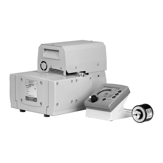
page 29 of 105 Abbreviations FPM: Fluoroelastomer Polyamide Polyethylene Polypropylene PPS: Polyphenylene sulfide Pump parts Position Component Diaphragm pump NT VARIO Controller CVC 3000 Pressure transducer VSK 3000 Mains connection ON/OFF switch Pump rating plate Inlet Outlet (silencer) Recessed grip / handle VACUU•BUS cable to controller Fuse holder Overpressure safety relief device... - Page 30 30 of 105 MD 4 NT VARIO / MV 2 NT VARIO (shown: MV 2 NT VARIO) MV 10 VARIO-B...
- Page 31 page 31 of 105 Rear side CVC 3000 Connection plug of the VACUU•BUS jacks for connection of line to NT VARIO / VARIO-B pump VACUU•BUS components (e.g., VSK 3000, coolant serial interface valve) RS-232 C rating plate Depending on technical version the con- nections of the VACUU•BUS cables are equipped with a nib.
-
Page 32: Use And Operation
page 32 of 105 Use and operation When switching on the controller CVC 3000 for the very first time, a menu to select the language of the controller menu is displayed. Select the de- sired language (e.g., ”English”) by turning the selection knob and press to confirm. - Page 33 page 33 of 105 + Make sure ventilation is adequate, especially if the pump is installed in an enclosure, or if the ambient tempera- ture is elevated. Provide external ventilation, if neces- sary. • Reduce the transmission of vibration. Prevent mechan- ical load due to rigid pipelines.
- Page 34 Secure hose connections at the pump appropriately, e.g., with hose clamps, to protect against accidental detach- ment. The VACUUBRAND controller CVC 3000 can only be operated with components compatible with the VACU- UBRAND VACUU•BUS system, (see “Accessories”, pg. 80).
-
Page 35: During Operation
page 35 of 105 Connect the pressure transducer via hose or small flange connection to the vacuum application. Do not mount the pressure transducer directly at the pump but close to the application. The cross-section of the tubing should be as large as possible. - Page 36 page 36 of 105 + Due to the high compression ratio, the pump might generate overpressure at the outlet. Check pressure compatibility with system components (e.g., exhaust tubing or exhaust valve) at the outlet. Ensure that the pump outlet is neither blocked nor restricted. + Maximum ambient temperature: 104 °F (40 °C) Check the maximum temperatures, if installing the pump in a cabinet or a housing.
-
Page 37: Shutdown & Storage
page 37 of 105 In case of overload, the motor is shut down by a self-hold thermal circuit breaker in the winding. Note: Only a manual reset is possible. Press the START/ STOP key at the controller to confirm the error message. Switch off the pump and disconnect the electrical power cord. -
Page 38: Vacuum Controller Cvc 3000
page 38 of 105 Vacuum controller CVC 3000 When switching on the controller CVC 3000 for the very first time, a menu to select the language of the controller menu is displayed. Select the de- sired language, e.g., ”English” by turning the selection knob and pressing to confirm. - Page 39 page 39 of 105 Selection knob • Press to reach the set-up menu of the function • Turn to choose the parameter you want to modify • Press to select the parameter you want to modify • Turn to change the set value of the parameter •...
- Page 40 page 40 of 105 Vacuum control to a preset vacuum value (here: 100 mbar/Torr/hPa) (with NT pump / with NT VARIO pump) Actual pressure is in the range ”Set vacuum + hys- teresis” (with NT pump) / Actual pressure = ”Set vacuum”...
- Page 41 page 41 of 105 Notes on selecting the function The CVC 3000 controller can be adapted to the specific application by choosing the appropriate function depending on the connected compo- nents and the requirements of the application. Automatic detection of the components When switching on the controller, the configuration of the connected com- ponents is checked automatically.
- Page 42 page 42 of 105 ”Vac control” • With pressure preselection, controls a NT VARIO / VARIO-B pump to maintain pinpoint control of that pressure. • Coolant valve ”Auto mode” • Provides fully automatic boiling point determination and adaptation with pinpoint precision, and optimization of pumping speed with NT VARIO / VARIO-B pumps.
-
Page 43: Menu Guide
page 43 of 105 Menu guide Pump down Speed Minimum Delay Duration Pump down - - - - - - Graphic - - - - - - - - - - - - - Back - - - - - - - 1013 . - Page 44 page 44 of 105 Vac control Set vacuum 75 Torr Speed Maximum Delay Vac control Duration - - - - - - Graphic - - - - - - - - - - - - - Back - - - - - - - 1013 .
-
Page 45: Pump Down Function
page 45 of 105 Pump down function ➨ Continuous pumping with pressure and time settings • Operation on demand of a speed controlled NT VARIO / VARIO-B pump Preselections + Use the selection knob to select the parameters. All parameters can be altered even while operation control is running. - Page 46 page 46 of 105 + If neither ”Minimum” nor ”Duration” is preset, process control has to be stopped by pressing key ”STOP”. The screen-shot shows the factory-set values. Pump down Pump down 10 mbar 760 Torr 00:03:50 Speed Minimum Delay Duration - - - - - - Graphic - - - - - - - - - - - - - Back - - - - - - -...
-
Page 47: Vac Control Function
page 47 of 105 Vac Control function ➨ Vacuum control to a preset vacuum value • Operation on demand of a speed controlled pump (NT VARIO / VARIO-B) Preselections + Use the selection knob to select the parameters. All parameters can be altered even while operation control is running. - Page 48 page 48 of 105 A preset ”Duration” (process time) has no effect if the process is stopped due to a preset ”Maximum” before ”Duration” is reached. The ”Duration” is adjustable between 1-1440 minutes (24 h) or can be set to ”Off”. ”Off” means that no endpoint of the process is defined. The screen-shots show the factory-set values.
- Page 49 page 49 of 105 Alternatively: Fine tuning: The set vacuum can be fine-adjusted by turning the selection knob while process is running. + Turn the selection knob. + A full turn causes a change of the set vacuum of 9 Torr (12 mbar). + Turning the knob one detent causes a change of the set vacuum of 1 Torr (mbar).
-
Page 50: Auto Mode
page 50 of 105 Auto mode ➨ Control of a NT VARIO / VARIO-B pump in ”Auto mode”: Automatic detection of boiling points, and automatic adjustment of determined boiling points as process parameters change. Preselections + Use the selection knob to set the parameters. + Sensitivity: The ”Sensitivity”... - Page 51 page 51 of 105 + Duration: ”Duration” determines the total process time since control start. The ”Duration” is adjustable between 1-1440 minutes (24 h) or can be set to ”Off”. A preset ”Duration” (process time) has no effect, if the process is stopped earlier by reaching the preset ”Minimum”.
-
Page 52: Program Function
page 52 of 105 Program function ➨ Permits ten programs to be defined and stored, each with up to ten program steps with preset values for vacuum and time. + Edit: Use to define the preset values for the process run: Time: Defines either the process runtime for each program step to reach a preset vacuum level or, if programming a ”Step”, the runtime after having achieved the vacuum level. - Page 53 page 53 of 105 Editing: + To select row: turn and press selection knob. + To adjust parameter: turn the selection knob. + To confirm parameter: Press selection knob. Controller will accept change and jump to the next parameter in the same row. + After 5 seconds without a change, the parameter is assumed to be the current setting.
-
Page 54: Application Example
page 54 of 105 Attention: If the controller is set to ”Defaults”: ”On”, all stored pro- grams will be deleted. Application example Example NT VARIO vacuum pump with speed control (e.g., with a rotary evap- orator): Degassing and automatic distillation with timing * If the pressure difference Program between the vacuum for... -
Page 55: Vacuulan Function
55 of 105 VACUULAN function ➨ Optimizes vacuum control for vacuum networks (e.g., VACUUBRAND VACUU•LAN) ➨ Permits on-demand operation of a speed-controlled pump (NT VARIO/VARIO-B) Preselections + Use the selection knob to select the parameters. + Set vacuum (the lower switch-off value): If the pressure drops below the ”Set vacuum”, a time-meter starts to run and the motor speed is re-... - Page 56 page 56 of 105 This screen-shot shows the factory-set values. VACUULAN VACUULAN 40 mbar 760 Torr 00:13:00 Set vacuum 19 Torr Switch on 150 Torr Delay 15 min - - - - - - Graphic - - - - - - - - - - - - - Back - - - - - - - When selecting ”Graphic”...
-
Page 57: Application Examples
page 57 of 105 Application examples Assembly of a vacuum system + Assemble vacuum connection lines between vacuum pump, CVC 3000 and vacuum application. + Assemble the vacuum connection line between the controller and the vacuum application, if the controller is not part of a pumping unit. + Assemble electrical connections. -
Page 58: Vacuum For Gel Dryer, Drying Chambers And Vacuum Concentrators
page 58 of 105 Vacuum for gel dryer, drying chambers and vacuum concentrators + Select function ”Pump down” function. ”Speed” ”HI” is recommended. For gel dryers set a lower speed if necessary (if the gels tend to crack). + Set ”Minimum” to prevent volatile components from evaporating. The process is stopped automatically as soon as ”Minimum”... - Page 59 page 59 of 105 + When setting a value for ”Duration” the controller switches off the pump when ”Duration” has passed even if a preset ”Minimum” is still not reached. + If neither ”Minimum” nor ”Duration” is preset, pumping down has to be finished by pressing the ”START/STOP”...
-
Page 60: Fore-Vacuum For High Vacuum Pumps
page 60 of 105 Fore-vacuum for high vacuum pumps Using the NT VARIO pump as fore-vacuum pump (also known as a ”roughing pump” or ”backing pump”) for a high vacuum pump (e.g. turbo- molecular with high fore-vacuum tolerance): + Use ”Pump down” function with ”Speed” set to ”HI” or + Use ”Vac control”... -
Page 61: Configuration
page 61 of 105 Configuration In the ”Configuration” menu the device parameters are preselected. After 20 seconds without action the function ”Configuration” and its sub- menus (except submenu ”Sensors”) are quit automatically without stor- ing any possibly changed parameter. Preselections + Use the selection knob to select the parameters. - Page 62 page 62 of 105 ther key. It is the user’s responsibility to ensure that no dangerous status of the system due to the automatic start- up can occur and to provide appropriate safety measures. If necessary, the user has to check prior to starting the process if the option ”Autostart”...
-
Page 63: Readjustment Of Vsk 3000
page 63 of 105 Readjustment of VSK 3000 The vacuum gauge head was adjusted using factory stan- NOTICE dards, which are traceable through regular calibration in an accredited laboratory (DAkkS calibration laboratory) to the German national pressure standard. Depending on the process and/or accuracy requirements, check the ad- justment and readjust if necessary. - Page 64 page 64 of 105 Adjustment under vacuum An adjustment under vacuum is only possible if the pressure is lower than 15 Torr (20 mbar) 0 mbar absolute. Evacuate the measurement connection of the VSK 3000 to a pressure < 0.1 Torr (mbar) (e.g., by applying a good two-stage rotary vane pump).
-
Page 65: Calibration In The Factory
65 of 105 Calibration in the factory Control of measuring equipment The VACUUBRAND DAkkS calibration laboratory is accredited by the Deutsche Akkreditierungsstelle GmbH (national accreditation body of the Federal Republic of Germany) for the measurable variable pressure in the pressure range from 7.5*10... -
Page 66: Cleaning The Pressure Transducer
page 66 of 105 Cleaning the pressure transducer ➨ Attention: Never use a pointed or sharp-edged tool to clean the pressure transducer. ➨ Never touch the ceramic diaphragm of the pres- sure transducer with hard objects. ➨ Fill the measurement chamber with a solvent (e.g., benzene) and allow sufficient cleaning time. -
Page 67: Part Ii
Part II page 67 of 105 Technology for Vacuum Systems Instructions for use Part II of II MD 4 NT VARIO Part II: MV 2 NT VARIO Interface parameters - Accessories - MV 10 VARIO-B Maintenance Speed controlled diaphragm pumps... - Page 68 page 68 of 105 Contents Part I..............1 Reset / Language selection ..........8 Safety information! ............11 Important information! ................11 General information ................13 Intended use..................13 Setting up and installing the equipment ..........14 Ambient conditions ................17 Operating conditions .................
- Page 69 Troubleshooting ............... 81 Replacing diaphragms and valves........85 Cleaning and inspecting the pump heads (MD 4 NT VARIO / MV 2 NT VARIO) ..........86 Replacing the diaphragm ..............88 Assembling the pump heads ............90 Cleaning and inspecting the pump heads (MV 10 VARIO-B) ..92 Replacing the diaphragm ..............
-
Page 70: Interface Parameters
The factory-set read and write commands are completely compatible with the VACUUBRAND CVC 2000 controller (see sections ”Read / Write commands CVC 2000”). An extended instruction set is available using the... -
Page 71: Setting Of The Interface
page 71 of 105 Setting of the interface Set the interface parameters directly at the controller CVC 3000. The fac- tory set values are underlined. Edit and confirm the interface parameters in the ”Configuration” menu in ”RS-232” submenu using the selection knob. ➨... -
Page 72: Read Commands "Cvc 2000
page 72 of 105 Read commands ”CVC 2000” Command Operation Response Description XXXX mbar/ IN_PV_1 current pressure unit according to preselections Torr/hPa IN_PV_2 current frequency XX.X Hz pump speed 0XXXX VACUU•LAN 1XXXX continuous pumping 2XXXX vacuum control without automatic 3XXXX vacuum control with automatic X0XXX no coolant valve... -
Page 73: Write Commands "Cvc 2000
page 73 of 105 Write commands ”CVC 2000” Command Operation Parameter Description continuous pumping vacuum control without automatic vacuum control with automatic OUT_MODE function optional: sensitivity: low optional: sensitivity: normal optional: sensitivity: high unit (mbar/Torr/hPa) according to pre- OUT_SP_1 set vacuum XXXX selection;... - Page 74 page 74 of 105 ** If remote operation is selected or deselected, the user has to ensure that no dangerous status of the system can occur due to the change of the mode of operation, and must take appropriate safety precautions, especially if selecting remote operation interferes with a locally oper- ated active process.
-
Page 75: Read Commands "Cvc 3000
page 75 of 105 Read commands ”CVC 3000” Command Operation Response Description IN_PV_1 current pressure XXXX.X mbar/Torr/hPa unit according to preselections IN_PV_2 current speed XXX% 1-100% or ”HI” IN_PV_3 time XX:XX h:m process runtime (hours:minutes) pressure of all connected sensors, IN_PV_X pressure XXXX.X XXXX.X ... - Page 76 page 76 of 105 Command Operation Response Description 0XXXXX pump off 1XXXXX pump on X0XXXX in-line valve closed X1XXXX in-line valve open XX0XXX coolant valve closed XX1XXX coolant valve open XXX0XX venting valve closed XXX1XX venting valve open XXXX0X VACUU•LAN XXXX1X Pump down status process...
-
Page 77: Write Commands "Cvc 3000
page 77 of 105 Command Operation Response Description IN_SP_4 delay XX:XX h:m hours:minutes (00:00 = Off) ”Maximum” for ”Vac control”, switch off IN_SP_5 XXXX mbar/Torr/hPa ”Minimum” for ”Pump down”) pressure unit according to preselections IN_SP_6 runtime XX:XX h:m process runtime (hours:minutes) time in program step y (0..9) IN_SP_P1y time... - Page 78 page 78 of 105 Command Operation Parameter Description unit according to preselection; see re- OUT-SP_1 set vacuum XXXX spective function for parameter range set vacuum with unit according to preselection; see re- OUT_SP_V XXXX venting spective function for parameter range OUT_SP_2 speed speed in % or ”HI”...
- Page 79 page 79 of 105 Command Operation Parameter Description internal sensor OUT_SENSOR 2...9 external sensors (if connected) * If remote operation is selected or deselected, the user has to ensure that no dangerous status of the system can occur due to the change of the mode of operation, and must also take appropriate safety precau- tions, especially if selecting remote operation interferes with a locally operated active process.
-
Page 80: Accessories
Extension cable VACUU•BUS, 2m ..............612552 Cable RS 232C, 9-pole, Sub-D ..............637837 Installation set CVC 3000 (clips and screws) ..........636593 Conversion of VACUUBRAND valves with DIN plug to VACUUBRAND valves with VACUU•BUS plug: VACUUBRAND-valve with DIN Conversion kit valve cable with plug VACUU•BUS plug... -
Page 81: Troubleshooting
page 81 of 105 Troubleshooting Fault Possible cause Remedy ❑ No display. ➨ Electrical power cord ✔ Plug in power cord. not plugged in, electri- Check fuse. cal supply failure? ➨ Device fuse blown? ✔ Identify cause of failure. Replace device fuse. ➨... - Page 82 page 82 of 105 Fault Possible cause Remedy ❑ No digital pressure ➨ Pressure transducer ✔ Contact local distributor. reading. defective? ❑ Digital pressure ➨ Overpressure at the ✔ Release pressure imme- reading is flashing, pressure transducer, diately (risk of bursting). one blip*.
- Page 83 page 83 of 105 Fault Possible cause Remedy ❑ Controller does ✔ Contact local distributor. not respond when operating any keys. No change after switching off/on. ❑ Pump does not ➨ Pump has been ex- ✔ Allow pump to run for start or stops im- posed to condensate? some minutes at maxi-...
- Page 84 page 84 of 105 Fault Possible cause Remedy ❑ Pump does not ➨ Pressure below ”Mini- ✔ Change switch off pres- achieve its ultimate mum” in Auto mode? sure (”Minimum”) if neces- vacuum or usual sary. pumping speed. ➨ Pump too hot? ✔...
-
Page 85: Replacing Diaphragms And Valves
page 85 of 105 Replacing diaphragms and valves + Please read section ”Replacing diaphragms and valves” com- pletely before starting maintenance. The pictures may show other versions of pumps. This does not change the method of replacing diaphragms and valves. ➨... -
Page 86: Cleaning And Inspecting The Pump Heads (Md 4 Nt Vario / Mv 2 Nt Vario)
- Regular maintenance will improve the lifetime of the pump and also protect both users and the environment. Service kit for MD 4 NT VARIO / MV 2 NT VARIO ........696861 Service kit for MV 10 VARIO-B ..............696827 Diaphragm key (width 66 mm) ..............636554... - Page 87 ➨ Lay the pump on its side. Support the pump appropriately. + Service only one side of the pump at a time to avoid the mixing of parts. View of the disassembled pump head parts (fig.: MD 4 NT VARIO) Pump head parts: F: Diaphragm A: Housing cover...
-
Page 88: Replacing The Diaphragm
page 88 of 105 ➨ Disassemble the housing cover (A) to check the valves (C). ➨ Unscrew eight Allen screws with a 5mm wide Allen key. Remove the housing cover (A) together with head cover (D), valves (C) and O-rings (B). + Never use a pointed or sharp-edged tool to remove parts (e.g., screw- driver). - Page 89 page 89 of 105 + Too few washers: The pump will not attain vacuum specification. Too many washers: Diaphragm clamping disc will hit head cover, causing noisy operation and possibly causing the pump to seize up. + If the old diaphragm is difficult to separate from the diaphragm support disc, immerse assembly in naphtha or petroleum ether.
-
Page 90: Assembling The Pump Heads
page 90 of 105 Assembling the pump heads ➨ Bring the diaphragms (F) into a position, in which they are in contact with the housing (J) and centered with respect to the bore. ➨ Put on head covers (D). + Pay attention to the correct orientation of the head covers: Align the nib at the head cover (D) with the notch of the housing cover (A). - Page 91 page 91 of 105 Replace diaphragms and valves of the opposite side of the pump in the same way! Checking the ultimate vacuum ➨ A fter any intervention at the equipment (e.g., repair / maintenance) the ultimate vacuum of the pump has to be checked. Only if the pump achieves its specified ultimate vacuum, the pump’s leak rate is low enough to ensure that no explosive atmospheres will occur in the inte- rior of the equipment.
-
Page 92: Cleaning And Inspecting The Pump Heads (Mv 10 Vario-B)
page 92 of 105 Cleaning and inspecting the pump heads (MV 10 VARIO-B) Tools required (metric): - Phillips screw driver size 2 - Open-ended wrench w/f 15/17/20 - 5 mm wide Allen key - Diaphragm key width 66 mm View of the disassembled pump head parts F: Diaphragm G: Diaphragm support disc H: Washer... - Page 93 page 93 of 105 ➨ Loosen the union nuts (N) of the hose con- nections at the pump heads with an open- ended wrench (w/f 15). ➨ Loosen the fittings (Q) at the pump heads with an open-ended wrench (w/f 17). ➨...
-
Page 94: Replacing The Diaphragm
page 94 of 105 Replacing the diaphragm ➨ Remove the punched part in the centre of the new diaphragm when replacing a diaphragm with square hole (see below). + Check diaphragm (F) for damage and re- place if necessary. ➨ Lift diaphragm carefully sidewise. + Never use a pointed or sharp-edged tool to lift the diaphragm. -
Page 95: Assembling The Pump Heads
page 95 of 105 ➨ Position new diaphragm (F) between dia- phragm clamping disc with square head screw (E) and diaphragm support disc (G). + Note: This is a double diaphragm consist- ing of two single diaphragms! Put the two diaphragms together with the printed sides outwards. - Page 96 page 96 of 105 ➨ Put on head cover (D). + Pay attention to the correct orientation of the head covers: Align the nib at the head cover (D) with the notch of the housing cover (A). + Make sure that the diaphragm stays centered with respect to the bore so that it will become clamped uniformly between housing (J) and head cover (D).
-
Page 97: Replacing The Valve At The Distributor (Outlet Side)
page 97 of 105 Replacing the valve at the distributor (outlet side) ➨ Loosen the union nut of the curved connecting hose (R) running di- rectly to the cover plate (L) of the distributor (P) with an open-ended wrench (w/f) 15. Loosen only the union nut at the pump head, not the one at the distributor. - Page 98 page 98 of 105 ➨ Tighten the union nuts (N) of the hose con- nections at the pump heads with an open- ended wrench w/f 15. Checking the ultimate vacuum ➨ A fter any intervention at the equipment (e.g., repair / maintenance) the ultimate vacuum of the pump has to be checked.
-
Page 99: Replacing The Device Fuse
MV 10 VARIO-B MD 4 NT VARIO / MV 2 NT VARIO ➨ Unscrew the fuse holder using a slotted screw driver. ➨ Replace the defective fuse by a fuse of the same type (see “Technical... -
Page 100: Repair - Maintenance - Return - Calibration
3 or 4. These devices cannot be checked, maintained or re- paired. Also decontaminated devices must not returned to VACUUBRAND due to a residual risk. The same conditions apply to on-site work. No repair, maintenance, return or calibration is possi- ble unless the correctly completed health and safety clearance form is returned. - Page 101 page 101 of 105 If you do not wish a repair on the basis of our quotation, the device may be returned to you disassembled and at your expense. In many cases, the components must be cleaned in the factory prior to repair. For cleaning we use an environmentally friendly water based process.
-
Page 102: Warranty
102 of 105 Warranty VACUUBRAND shall be liable for insuring that this prod- uct, including any agreed installation, has been free of de- fects at the time of the transfer of risk. VACUUBRAND shall not be liable for the consequences... -
Page 103: Health And Safety Clearance Form
* Contact the VACUUBRAND service absolutely before dispatching the device. ** Devices which have been in contact with biological substances of risk level 3 or 4 cannot be checked, main- tained or repaired. Also decontaminated devices must not returned to VACUUBRAND due to a residual risk. ☐... -
Page 104: Ec Declaration Of Conformity Of The Machinery
Membranvakuumpumpe / Diaphragm vacuum pump / Pompe à membrane: Typ / Type / Type: MD 4 NT VARIO / MV 2 NT VARIO / MV 10 VARIO-B Artikelnummer / Order number / Numéro d‘article: 736300, 736301, 736302 / 738100, 738101, 738102 / 710500, 710501, 710502, 2614172 Seriennummer / Serial number / Numéro de série: Siehe Typenschild / See rating plate / Voir... - Page 105 Alfred-Zippe-Str. 4 · 97877 Wertheim / Germany T +49 9342 808-0 · F +49 9342 808-5555 info@vacuubrand.com · www.vacuubrand.com VACUUBRAND GMBH + CO KG - Technology for Vacuum Systems - © 2016 VACUUBRAND GMBH + CO KG Printed in Germany Manual-no.: 999163 / 03/08/2016...
Need help?
Do you have a question about the MD 4 NT VARIO and is the answer not in the manual?
Questions and answers