Banner L-GAGE LE250 IO-Link Instruction Manual
Laser gauging sensors
Hide thumbs
Also See for L-GAGE LE250 IO-Link:
- Instruction manual (47 pages) ,
- Quick start manual (10 pages) ,
- Instruction manual (45 pages)

Subscribe to Our Youtube Channel
Related Manuals for Banner L-GAGE LE250 IO-Link


Summary of Contents for Banner L-GAGE LE250 IO-Link
- Page 1 ® L-GAGE LE250/550 IO-Link Laser Gauging Sensors Instruction Manual Original Instructions 194205 Rev. A 2 December 2016 © Banner Engineering Corp. All rights reserved 194205...
-
Page 2: Table Of Contents
......................29 6.1 Performance Curves ....................... 30 6.2 Dimensions ........................... 31 7 Troubleshooting ......................32 8 Sensor Menu Full Map ....................33 9 Accessories ........................34 9.1 Cordsets ..........................34 9.2 Brackets ..........................34 10 Banner Engineering Corp. Limited Warranty .............. 35... -
Page 3: Product Description
® L-GAGE LE250/550 IO-Link Laser Gauging Sensors 1 Product Description • Easy to set up and use with a 2-line, 8-character display • Various sizes of visible red laser, depending on target size, distance, and color characteristics • Sensing range options up to 1 meter •... -
Page 4: Features And Indicators
® L-GAGE LE250/550 IO-Link Laser Gauging Sensors 1.2.1 Features and Indicators Three LED indicators provide ongoing indication of the sensing Discrete Output 1 status. LED Indicator Power LED Indicator Display Power LED Solid Green = Normal operation, power On and laser On Indicator Flashing Green (1 Hz) = Power On and laser Off (laser enable Discrete Output 2... -
Page 5: Laser Description And Safety Information
® L-GAGE LE250/550 IO-Link Laser Gauging Sensors Escape Button Press Escape to: • Leave the current menu and return to the parent menu • Return to Run mode from the Quick Menu Important: Pressing Escape discards any unsaved programming changes. In the Sensor Menu, a return arrow in the upper left corner of the display indicates that pressing Escape returns to the parent menu. - Page 6 ® L-GAGE LE250/550 IO-Link Laser Gauging Sensors 1.3 Class 1 Laser Models Class 1 lasers are lasers that are safe under reasonably foreseeable conditions of operation, including the use of optical instruments for intrabeam viewing. CLASS 1 LASER PRODUCT Laser wavelength: 650 Output: <...
-
Page 7: Sensor Installation
® L-GAGE LE250/550 IO-Link Laser Gauging Sensors 2 Sensor Installation NOTE: Handle the sensor with care during installation and operation. Sensor windows soiled by fingerprints, dust, water, oil, etc. may create stray light that may degrade the peak performance of the sensor. Blow the window clear using filtered, compressed air, then clean as necessary using 70% isopropyl alcohol and cotton swabs or water and a soft cloth. -
Page 8: Wiring Diagrams
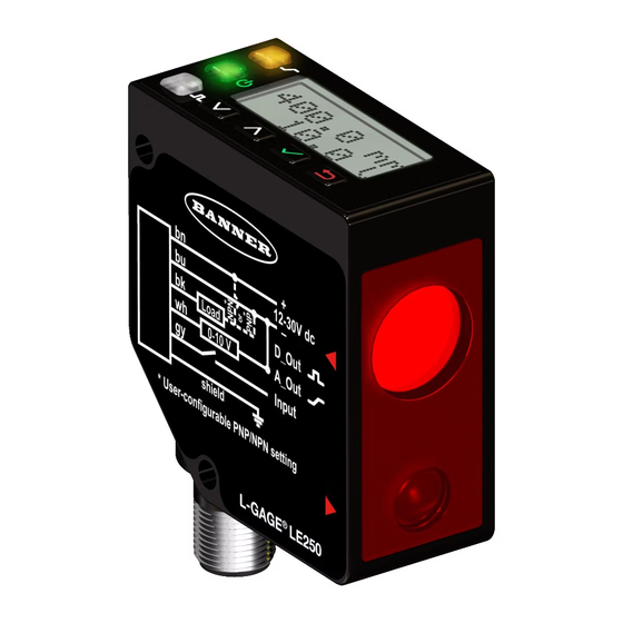
® L-GAGE LE250/550 IO-Link Laser Gauging Sensors 2.3 Wiring Diagrams 12–30 V dc – D1_Out / IO-Link Load 1 = Brown D2_Out Load 2 = White Input 3 = Blue 4 = Black shield 5 = Gray Figure 11. IO-Link Models www.bannerengineering.com - Tel: 763.544.3164... -
Page 9: Sensor Programming
® L-GAGE LE250/550 IO-Link Laser Gauging Sensors 3 Sensor Programming Program the sensor using the buttons on the sensor or the remote input (limited programming options). From Run mode, use the buttons to access the Quick Menu and the Sensor Menu. See Quick Menu on page 9 and Sensor Menu (MENU) -
Page 10: Sensor Menu (Menu)
® L-GAGE LE250/550 IO-Link Laser Gauging Sensors 3.2 Sensor Menu (MENU) Access the Sensor Menu by pressing Enter from Run mode, when MENU is displayed. The Sensor Menu includes several submenus that provide access to view and change sensor settings and to view sensor information. Sensor Menu (See Sensor Menu Full Map for the complete map) Access discrete 1 output settings... - Page 11 ® L-GAGE LE250/550 IO-Link Laser Gauging Sensors NOTE: Follow procedure for the TEACH/SET method (highlighted in black box) chosen in the TEACH Selection menu. Pulse Timing (T) Mode Timeout is 60 seconds. 0.04 seconds < T < 0.8 seconds Timing between Pulse groups > 1 second Enter Remote TEACH RMT TCH with measurement value Teaching..(D1SPt1) TchSPt1 (D1) with measurement value, then to TchSPt2 (D1)
-
Page 12: Locking And Unlocking The Sensor
® L-GAGE LE250/550 IO-Link Laser Gauging Sensors Table 1: Window Size (WndSize) Variable LE250 Models LE550 Models Variable LE250 Models LE550 Models 1 mm 10 mm 100 mm 300 mm 10 mm 50 mm 150 mm 500 mm 50 mm 100 mm 250 mm 800 mm... -
Page 13: Discrete Output Menu (Dx_Out)
® L-GAGE LE250/550 IO-Link Laser Gauging Sensors 3.5 Discrete Output Menu (Dx_OUT) Use this menu to view or change • Setpoints • Midpoint MENU D1_OUT Tch2Pt TchSPt1 TchSPt1 100 mm D1_OUT Tch2Pt • Mode Tch2Pt TchSPt2 TchSPt2 1000 mm • Timers TchMid WndSize WndSize 300 mm... - Page 14 ® L-GAGE LE250/550 IO-Link Laser Gauging Sensors Action Result The selected TEACH mode and "Teaching" display while the sensor is being taught. TEACH Accepted Navigate: MENU > Dx_OUT > Tch2Pt > TchSPt1 The new value is shown on the second line of the display and flashes before it is saved and the sensor returns to the parent menu.
-
Page 15: Midpoint Teach
® L-GAGE LE250/550 IO-Link Laser Gauging Sensors 3.5.2 Midpoint TEACH The Midpoint TEACH uses both the window size and the Output ON TEACH midpoint to determine the actual measurement window. For example, a window of 200 mm with a midpoint of 600 mm places the measurement window from 500 mm to Output OFF 700 mm. - Page 16 ® L-GAGE LE250/550 IO-Link Laser Gauging Sensors Method Action Result Pulse the remote input 1 to 6 times to select the desired window size. Window Size Pulses LE250 LE550 1 mm 10 mm Remote Input (Sets A_OUT 10 mm 50 mm The new value flashes and the sensor and D_OUT returns to Run mode.
-
Page 17: Adjust Switch Point One
® L-GAGE LE250/550 IO-Link Laser Gauging Sensors Action Result "TchMdpt Teaching" displays while the sensor is being taught. TEACH Accepted The new value displays on the second line of the display, flashes, and the sensor Five-pulse the remote input. returns to Run mode. TEACH Not Accepted "FAIL"... -
Page 18: Adjust Switch Point
® L-GAGE LE250/550 IO-Link Laser Gauging Sensors Action Result "TchSPt Teaching" displays while the sensor is being taught. TEACH Accepted The new value is shown on the second line of the display and flashes before it is saved Navigate: MENU > Dx_OUT > TchSPt and the sensor returns to "Dx_OUT TchSPt". - Page 19 ® L-GAGE LE250/550 IO-Link Laser Gauging Sensors Mode Description Alarm Alarm Mode: The Discrete Output is Off while a target is detected by the sensor at any distance. When a loss of signal occurs, the Discrete Output is On. This mode has no associated thresholds. Health Health Mode: The Discrete Output is On while a target is detected by the sensor at any distance.
-
Page 20: Switch Point Reference (Sptref)
® L-GAGE LE250/550 IO-Link Laser Gauging Sensors Action Result Pulse the remote input 1 to 6 times to select the desired mode. Pulses Mode Alarm Health Swtch The selected mode flashes and the sensor returns to Run mode. Swtch 3.5.8 Switch Point Reference (SPtRef) The SPtRef menu only displays for a discrete output when it is set to switch mode. -
Page 21: Timer
® L-GAGE LE250/550 IO-Link Laser Gauging Sensors 3.5.10 Timer The Timer option sets the delays and timers. On/Off Delays and On/Off One-Shot timers can Output be programmed between 1 to 9999 ms (a value of 0 disables the delay/timer). Figure 18 page 21 defines how the delays/timers affect the output behavior. -
Page 22: Measure Menu (Measure)
® L-GAGE LE250/550 IO-Link Laser Gauging Sensors Navigate: MENU > INPUT > Type Remote Input: Not available Default: Disabled Input Type Description Teach The remote input is used to TEACH and program the sensor. (Default) LasrEnbl The remote input is used to control when the laser emitter is On/Off. SyncMstr The remote input is used as the Master Sync output to an attached Slave sensor (see Sync Master/... -
Page 23: Display Menu (Display)
® L-GAGE LE250/550 IO-Link Laser Gauging Sensors 3.8 Display Menu (DISPLAY) Use this menu to view or change the: • Display units • Display orientation • Sleep mode settings MENU DISPLAY Units mm DISPLAY Units Units in Zero Near DISPLAY Zero Zero Far Select Menu Item Shift Off... -
Page 24: Sleep
® L-GAGE LE250/550 IO-Link Laser Gauging Sensors Remote Input: Not available Default: Normal Figure 22. LE550 Normal Display Orientation Figure 23. LE550 Inverted Display Orientation 3.8.5 Sleep The Sleep option sets when the display is put to sleep. Four timing options are available: 1, 5, 15, or 60 minutes. Sleep mode is disabled by default. -
Page 25: Reset Menu (Reset)
® L-GAGE LE250/550 IO-Link Laser Gauging Sensors 3.10 Reset Menu (RESET) Use this menu to restore the sensor to the factory default settings. MENU RESET Navigate: MENU > RESET. Select Yes to apply the RESET No factory defaults; select No to return to the Reset option RESET Yes without changing any sensor settings. -
Page 26: Sync Master/Slave
® L-GAGE LE250/550 IO-Link Laser Gauging Sensors 4 Sync Master/Slave Two LE250/550 Laser sensors may be used together in a single sensing application. To eliminate crosstalk between the two sensors, configure one sensor to be the master and one to be the slave. In this mode, the sensors alternate taking measurements and the response speed doubles. -
Page 27: Additional Remote Teach Procedures
® L-GAGE LE250/550 IO-Link Laser Gauging Sensors 5 Additional Remote TEACH Procedures 5.1 TEACH Both Discrete Output Switch Points Together Use the following procedure to teach both Discrete Output switch points at the same time using the remote input. This feature is not available using the buttons. - Page 28 ® L-GAGE LE250/550 IO-Link Laser Gauging Sensors Action Result "RMT TCH" and the current measurement Single-pulse the remote input. value display. 2. Present the target. Action Result "RMT TCH"and the target's measurement Present the midpoint (switch point) target. value display. 3.
-
Page 29: Specifications
® L-GAGE LE250/550 IO-Link Laser Gauging Sensors 6 Specifications Supply Voltage (Vcc) Sensing Beam 12 to 30 V dc Class 2 laser models: visible red, 650 nm Class 1 laser models: visible red, 650 nm Power and Current Consumption, exclusive of load Normal Run Mode: 1.7 W, Current consumption <... -
Page 30: Performance Curves
® L-GAGE LE250/550 IO-Link Laser Gauging Sensors Environmental Rating Required Overcurrent Protection IEC IP67, NEMA 6 WARNING: Electrical connections Operating Conditions must be made by qualified −20 °C to +55 °C (−4 °F to +131°F) personnel in accordance with local 90% at +55 °C maximum relative humidity (non-condensing) and national electrical codes and Storage Temperature... -
Page 31: Dimensions
® L-GAGE LE250/550 IO-Link Laser Gauging Sensors LE250 Dual Discrete Models LE550 Dual Discrete Models 0.150 0.125 0.100 0.075 0.050 0.030 0.025 1000 DISTANCE (mm) DISTANCE (mm) Figure 28. Temperature Effect Figure 29. Temperature Effect 6.2 Dimensions All measurements are listed in millimeters [inches], unless noted otherwise. 0.6 mm [0.02”] 56 mm... -
Page 32: Troubleshooting
Power LED is flashing The laser shut off, the Power LED flashes Contact Banner Engineering to resolve. red and Output LEDs flash amber at 1Hz, and the display is blank. The laser has experienced a fault. -
Page 33: Sensor Menu Full Map
® L-GAGE LE250/550 IO-Link Laser Gauging Sensors 8 Sensor Menu Full Map Top Menu Sub Menus Enter MENU D1_OUT Tch2Pt TchSPt1 TchSPt1 100 mm D1_OUT Tch2Pt Mode Top Menu Tch2Pt TchSPt2 TchSPt2 1000 mm D1_OUT TchMid TchMid WndSize WndSize 300 mm TchMid TchMdPt TchMdPt 500 mm TchMid Offset... -
Page 34: Accessories
® L-GAGE LE250/550 IO-Link Laser Gauging Sensors 9 Accessories 9.1 Cordsets All measurements are listed in millimeters, unless noted otherwise. 5-Pin Threaded M12/Euro-Style Cordsets—with Shield Model Length Style Dimensions Pinout (Female) MQDEC2-506 1.83 m (6 ft) 44 Typ. MQDEC2-515 4.57 m (15 ft) Straight MQDEC2-530 9.14 m (30 ft) -
Page 35: Banner Engineering Corp. Limited Warranty
10 Banner Engineering Corp. Limited Warranty Banner Engineering Corp. warrants its products to be free from defects in material and workmanship for one year following the date of shipment. Banner Engineering Corp. will repair or replace, free of charge, any product of its manufacture which, at the time it is returned to the factory, is found to have been defective during the warranty period.
Need help?
Do you have a question about the L-GAGE LE250 IO-Link and is the answer not in the manual?
Questions and answers