
Related Manuals for Banner L-GAGE LH Series


Summary of Contents for Banner L-GAGE LH Series
- Page 1 ® L-GAGE LH Series Sensor Instruction Manual Original Instructions 152154 Rev. D 9 May 2017 © Banner Engineering Corp. All rights reserved 152154...
-
Page 2: Table Of Contents
..................................12 4.3.3 LED Indicators and Outputs ..............................13 4.4 Dimensions ......................................14 5 Accessories ..................................15 5.1 Brackets ....................................... 15 5.2 INTUSB485-LH Adapter ..................................15 5.3 Cordsets .......................................15 6 Banner Engineering Corp. Limited Warranty ........................18 6.1 Contact Us ......................................18... -
Page 3: Introduction
Each LH Series Laser Displacement Sensor Kit includes the following: • 1 LH Series High-Performance Laser Displacement Sensor • 1 CD containing Banner LH Series Configurator (p/n 13597) and LH Series Laser Displacement Sensor Configurator Software Manual (p/n 150307) • This Installation Guide (p/n 152154) Note: A INTUSB485-LH converter to connect the LH Series Sensor to a PC can be purchased separately. -
Page 4: Lh Series Installation And Setup
® L-GAGE LH Series Sensor 2 LH Series Installation and Setup 2.1 Cable/Connector Wiring Color Description White 4-20 mA output source Brown Power supply 18–30 V dc 18-30V dc Shield (bundled with white 4-20 mA output return – wire inside blue foil wrap) RS-485 GND Yellow RS-485 RX- / TX-... -
Page 5: Thickness Delta Measurement Installation
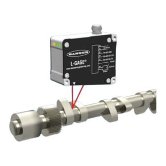
® L-GAGE LH Series Sensor LH Series TARGET Sensor Displacement Measurement Installation Tips Target motion must be perpendicular to emitter/receiver axis. Some targets (those with a stepped plane facing the sensor, a boundary line, or rounded targets) pose specific problems for sensing distances. -
Page 6: Handling And Storage
If the ideal master/slave separation cannot be achieved due to application restrictions, the thickness delta measurement can still be configured to work properly by adjusting the Thickness Delta Offset parameter via the Banner LH Series Configurator software. Thickness Delta Measurement Installation Steps: 1. -
Page 7: Lh Series Configurator Software
® L-GAGE LH Series Sensor 3 LH Series Configurator Software The LH Series Configurator CD (P/N 13597) includes the LH Series Configurator software and the LH Series Laser Displacement Sensor Configurator Software Manual (P/N 150307). 3.1 Software Installation The LH Series Configurator software is compatible with Windows XP, Windows Vista, and Windows 7 (32-bit and 64-bit). To install the LH Series Configurator software: 1. -
Page 8: Starting Up The Lh Series Configurator
6. When the installation completes, click the Finish button. 3.2 Starting Up the LH Series Configurator To start up the software, double-click the Banner LH Series Configurator icon on the desktop, or launch the Banner LH Series Configurator from the the Start menu. -
Page 9: Lh Series Configurator Main Screen
® L-GAGE LH Series Sensor 3.3 LH Series Configurator Main Screen www.bannerengineering.com - Tel: 763.544.3164... - Page 10 Used for monitoring communications traffic. Help Show Help Launches the Main Help contents. About Banner LH Series Displays software version information. Configurator LH Assistant The LH Assistant button launches the LH Assistant, which includes wizards to guide the user step-by-step through setting up a single displacement sensor, a master/slave pair of sensors for a thickness delta measurement, or a network of sensors.
-
Page 11: Specifications
® L-GAGE LH Series Sensor 4 Specifications 4.1 General Specifications Supply Voltage and Current Construction 18 to 30 V dc (10% maximum ripple); 250 mA maximum at 24 V dc (exclusive of Aluminum housing and cover plate; glass lens; load) PVC and nickel-plated brass cable Supply Protection Circuitry Environmental Rating... -
Page 12: Indicators
® L-GAGE LH Series Sensor 4.3 Indicators 1. Amber Signal LED 2. Green Power LED 4.3.1 Green Power LED The Green Power LED indicates the operating status of the sensor. Power Indicates LED Status Power is OFF Flashing Target detected in middle 5% of measurement range ON Solid Sensor is operating normally (power is ON, Laser enabled) 4.3.2 Amber Signal LED... -
Page 13: Led Indicators And Outputs
® L-GAGE LH Series Sensor 4.3.3 LED Indicators and Outputs Series Out of Out of Measurement Measuring measurement measurement range range range range Green Green LED Indicator Flashing Amber LED Indicator Green flashing is LH30 = 30 mm at middle 5% of measurement range LH80 = 80 mm LH150 = 150 mm... -
Page 14: Dimensions
® L-GAGE LH Series Sensor 4.4 Dimensions www.bannerengineering.com - Tel: 763.544.3164... -
Page 15: Accessories
® L-GAGE LH Series Sensor 5 Accessories 5.1 Brackets SMBLH1 SMBLH30 • LH series adjustable bracket • Main mounting bracket for • Brackets for thickness and LH Series sensor displacement • T-slot or “bolt-on” bracket measurement for mounting one sensor •... - Page 16 ® L-GAGE LH Series Sensor 8-Pin Threaded M12/Euro-Style Cordsets with Shield Model Length Style Dimensions Pinout (Female) 1 = White 5 = Gray 2 = Brown 6 = Green MQLH-830-F 9.14 m (30 ft) 3 = Shield 7 = Blue 4 = Yellow 8 = Shield 8-Pin Threaded M12/Euro-Style Cordsets with Shield―Double Ended...
- Page 17 ® L-GAGE LH Series Sensor 8-Pin Threaded M12/Euro-Style Splitter Cordsets with Shield—Flat Junction Model Branches (Female) Trunk (Male) Pinout CSB3-M1281M1282-LH 0.60 m 0.30 m Female Male 2X ø 4.5 18.0 [0.18"] [0.71"] 40 Typ. [1.58"] ø 14.5 [0.57"] M12 x 1 44 Typ.
-
Page 18: Banner Engineering Corp. Limited Warranty
MERCHANTABILITY OR FITNESS FOR A PARTICULAR PURPOSE), AND WHETHER ARISING UNDER COURSE OF PERFORMANCE, COURSE OF DEALING OR TRADE USAGE. This Warranty is exclusive and limited to repair or, at the discretion of Banner Engineering Corp., replacement. IN NO EVENT SHALL BANNER ENGINEERING CORP. BE LIABLE TO BUYER OR ANY OTHER PERSON OR ENTITY FOR ANY EXTRA COSTS, EXPENSES, LOSSES, LOSS OF PROFITS, OR ANY INCIDENTAL, CONSEQUENTIAL OR SPECIAL DAMAGES RESULTING FROM ANY PRODUCT DEFECT OR FROM THE USE OR INABILITY TO USE THE PRODUCT, WHETHER ARISING IN CONTRACT OR WARRANTY, STATUTE, TORT, STRICT LIABILITY, NEGLIGENCE, OR OTHERWISE. - Page 19 ® L-GAGE LH Series Sensor Japan Address: Phone: +81 (0)6 6309 0411 Banner Engineering Japan Website: www.bannerengineering.co.jp Cent-Urban Building 305 3-23-15 Nishi-Nakajima Yodogawa-Ku Email: mail@bannerengineering.co.jp Osaka 532-0011, Japan Taiwan Address: Phone: +886 (0)2 8751 9966 Banner Engineering Taiwan Website: www.bannerengineering.com.tw 8F-2, No.
Need help?
Do you have a question about the L-GAGE LH Series and is the answer not in the manual?
Questions and answers