Banner L-GAGE LE250 Quick Start Manual
Hide thumbs
Also See for L-GAGE LE250:
- Instruction manual (47 pages) ,
- Quick start manual (10 pages) ,
- Instruction manual (45 pages)
Table of Contents
Advertisement
Quick Links
L-GAGE
LE250/550 IO-Link Laser Sensors
®
Quick Start Guide
This guide is designed to help you set up and install the L-GAGE
performance, troubleshooting, dimensions, and accessories, please refer to the Instruction Manual at www.bannerengineering.com. Search
for p/n 194205 to view the manual. Use of this document assumes familiarity with pertinent industry standards and practices.
WARNING: Not To Be Used for Personnel Protection
Never use this device as a sensing device for personnel protection. Doing so could lead to serious injury or
death. This device does not include the self-checking redundant circuitry necessary to allow its use in personnel safety
applications. A sensor failure or malfunction can cause either an energized or de-energized sensor output condition.
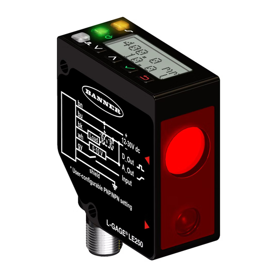
Features and Indicators
Discrete Output 1
LED Indicator
Power LED
Indicator
Discrete Output 2
LED Indicator
Push Buttons
Figure 1. LE IO-Link Sensor Features
Laser Description and Safety Information
CAUTION: Use of controls or adjustments or performance of procedures other than those specified herein may result
in hazardous radiation exposure. Do not attempt to disassemble this sensor for repair. A defective unit must be
returned to the manufacturer.
Class 2 Laser Models
CAUTION: Never stare directly into the sensor lens. Laser light can damage your eyes. Avoid placing any mirror-
like object in the beam. Never use a mirror as a retroreflective target.
For Safe Laser Use - Class 2 Lasers
Reference IEC 60825-1:2007, Section 8.2.
Original Document
194204 Rev. B
®
Three LED indicators provide ongoing indication of the sensing status.
Power LED Indicator
Display
Discrete Output LED Indicators
•
Do not stare at the laser.
•
Do not point the laser at a person's eye.
•
Mount open laser beam paths either above or below eye level, where practical.
•
Terminate the beam emitted by the laser product at the end of its useful path.
2 December 2016
LE Laser Gauging Sensor. For complete information on programming,
Solid Green = Normal operation, power On and laser On
Flashing Green (1 Hz) = Power On and laser Off (laser enable mode)
Solid Amber = Discrete Output is On
Off = Discrete Output is Off
194204
Advertisement
Table of Contents

Subscribe to Our Youtube Channel
Related Manuals for Banner L-GAGE LE250


Summary of Contents for Banner L-GAGE LE250
- Page 1 L-GAGE LE250/550 IO-Link Laser Sensors ® Quick Start Guide ® This guide is designed to help you set up and install the L-GAGE LE Laser Gauging Sensor. For complete information on programming, performance, troubleshooting, dimensions, and accessories, please refer to the Instruction Manual at www.bannerengineering.com. Search for p/n 194205 to view the manual.
-
Page 2: Sensor Installation
® L-GAGE LE250/550 IO-Link Laser Sensors Class 2 Lasers Class 2 lasers are lasers that emit visible radiation in the wavelength range from 400 nm to 700 nm, where eye protection is normally afforded by aversion responses, including the blink reflex. This reaction may be expected to provide adequate protection under reasonably foreseeable conditions of operation, including the use of optical instruments for intrabeam viewing. -
Page 3: Mount The Sensor
® L-GAGE LE250/550 IO-Link Laser Sensors Correct Incorrect Correct Incorrect Figure 7. Orientation for a height difference Figure 8. Orientation for a color or luster Figure 9. Orientation for a highly reflective difference target Applying tilt to sensor may improve performance on reflective targets. The direction and magnitude of the tilt depends on the application, but a 15°... -
Page 4: Sensor Programming
® L-GAGE LE250/550 IO-Link Laser Sensors Down and Up Buttons Press Down and Up to: • Access the Quick Menu from Run mode • Navigate the menu systems • Change programming settings When navigating the menu systems, the menu items loop. Press Down and Up to change setting values. -
Page 5: Sensor Menu (Menu)
® L-GAGE LE250/550 IO-Link Laser Sensors Quick Menu access Sensor Run Mode Menu (Top Menu) D1 SPt1 (value) set value with D1 SPt2*(value) Save setting and return to Quick Menu D2 SPt1 (value) Cancel and return to Quick Menu D2 SPt2*(value) Spt2 not available unless in Window Mode Figure 13. -
Page 6: Specifications
® L-GAGE LE250/550 IO-Link Laser Sensors Top Menu Sub Menus Enter MENU D1_OUT Tch2Pt TchSPt1 TchSPt1 100 mm D1_OUT Tch2Pt Mode Top Menu Tch2Pt TchSPt2 TchSPt2 1000 mm D1_OUT TchMid TchMid WndSize WndSize 300 mm TchMid TchMdPt TchMdPt 500 mm TchMid Offset Offset 0 mm LE Series User Interface... - Page 7 ® L-GAGE LE250/550 IO-Link Laser Sensors Output Configuration Minimum Window Size D1_Out: IO-Link, Push/pull LE250: 1 mm (0.039 inches) D2_Out: PNP LE550: 10 mm (0.39 inches) Output Ratings Boresighting 100 mA maximum capability each output LE250: 4 mm radius at 400 mm Saturation: Less than 2 V LE550: 1 cm radius at 1 m Off-State Leakage Current: Less than 50 µA PNP at 30 V (N.A.
-
Page 8: Performance Curves
Banner Engineering Corp. Limited Warranty Banner Engineering Corp. warrants its products to be free from defects in material and workmanship for one year following the date of shipment. Banner Engineering Corp. will repair or replace, free of charge, any product of its manufacture which, at the time it is returned to the factory, is found to have been defective during the warranty period. This warranty does not cover damage or liability for misuse, abuse, or the improper application or installation of the Banner product.
Need help?
Do you have a question about the L-GAGE LE250 and is the answer not in the manual?
Questions and answers