Table of Contents
Advertisement
Quick Links
Advertisement
Table of Contents

Related Manuals for Sunell SN-TPC6401KT/F


Summary of Contents for Sunell SN-TPC6401KT/F
- Page 1 Thermal Imaging Integrated Network Camera User Manual Issue V1.0 Date 2019-08-06...
- Page 3 Thermal Imaging Integrated Network Camera User Manual Precautions Precautions Precautions Fully understand this document before using this device, and strictly observe rules in this document when using this device. If you install this device in public places, provide the tip "You have entered the area of electronic surveillance" in an eye- catching place.
- Page 4 Thermal Imaging Integrated Network Camera Precautions User Manual Strictly conform to local electrical safety standards and use power adapters which are marked with the LPS standard when installing and using this device. Otherwise, this device may be damaged. Use accessories delivered with this device.
- Page 5 Thermal Imaging Integrated Network Camera User Manual Precautions Use a soft and dry cloth to clean the device body. In case that the dirt is hard to remove, use a dry cloth dipped in a small amount of mild detergent and gently wipe the device, and then dry it again.
-
Page 6: Table Of Contents
Thermal Imaging Integrated Network Camera Contents User Manual Contents 1 Product Overview ....................1 1.1 Thermal Imaging Principles and Advantages ..............1 1.2 Device Structure ......................1 1.3 Cable Connection ......................3 1.4 Functions and Features ....................4 2 Device Dimensions ....................5 3 Installation ........................ - Page 7 Thermal Imaging Integrated Network Camera User Manual Contents 6.6 FFC Control ......................... 37 6.7 Noise Reduction ......................38 6.8 Enhance Image ......................39 7 Technical Specifications ..................41 A Troubleshooting....................45 B Common Emission Rate ..................47 Issue V1.0 (2019-08-06)
-
Page 9: Product Overview
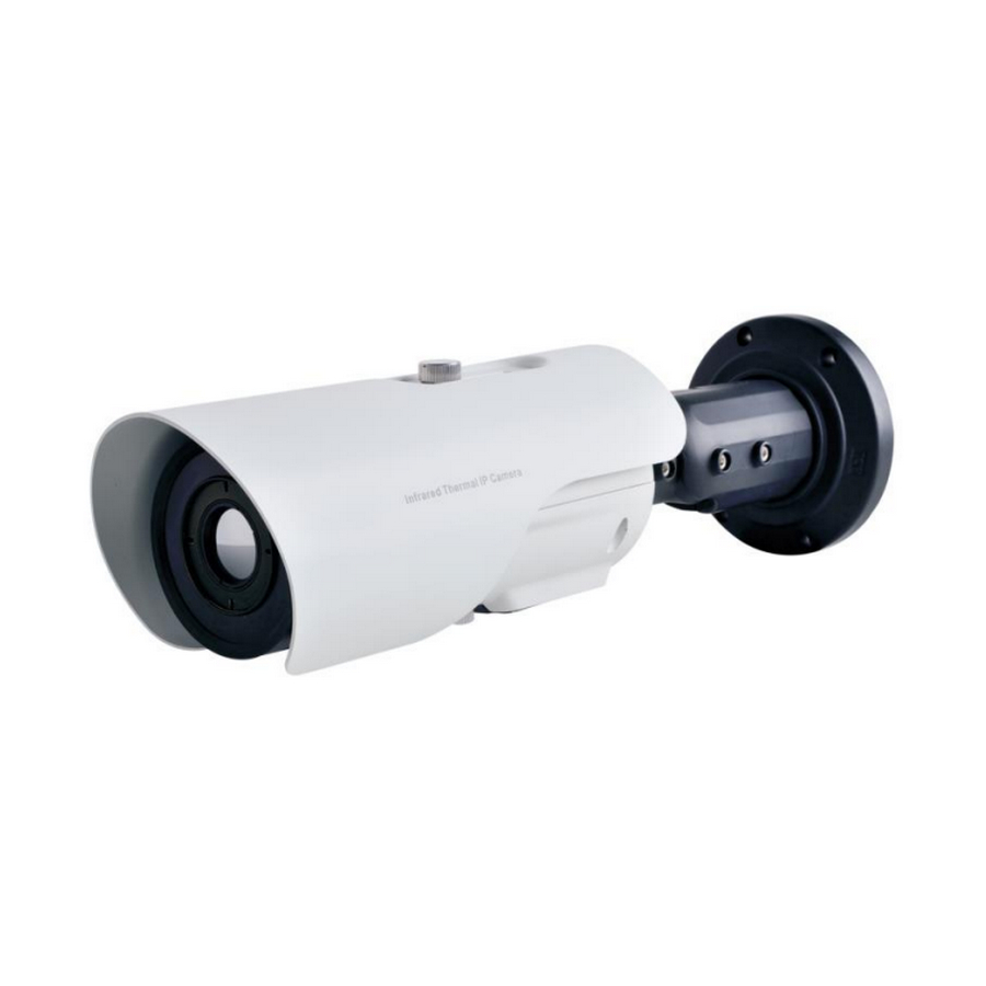
Thermal Imaging Integrated Network Camera Product Overview User Manual Product Overview 1.1 Thermal Imaging Principles and Advantages For any object, as long as its temperature is above the absolute zero (-273.15°C), although the object does not give out light, it can radiate infrared. The infrared is also known as thermal radiation. - Page 10 Thermal Imaging Integrated Network Camera Product Overview User Manual Figure 1-1 Appearance and interfaces of the thermal imaging integrated network camera Table 1-1 Interfaces of camera Physical Interface Connection Reset button The configuration resumes to the factory settings (RESET) after you press the reset button for 3s. The default value of IP is 192.168.0.121.
-
Page 11: Cable Connection
Thermal Imaging Integrated Network Camera Product Overview User Manual 1.3 Cable Connection Figure 1-2 the multi-connector combination cable of the thermal imaging integrated network camera. For details about the multi-connector combination cable, see Table 1- Figure 1-2 Multi-connector combination cable Table 1-2 Multi-connector combination cable Color Functions... -
Page 12: Functions And Features
Thermal Imaging Integrated Network Camera Product Overview User Manual Color Functions Connection tilt. White RS 485- 1.4 Functions and Features Using the uncooled infrared focal plane sensor Detecting the infrared wavelength ranging from 8 um to 14 um ... -
Page 13: Device Dimensions
Thermal Imaging Integrated Network Camera Device Dimensions User Manual Device Dimensions Figure 2-1 shows the dimensions of device. Figure 2-1 Dimensions (unit: mm) Issue V1.0 (2019-08-06) -
Page 14: Installation
Thermal Imaging Integrated Network Camera Installation User Manual Installation 3.1 Preparations You may need the tools and accessories shown in Table 3-1 during the installation (you need to prepare the tools by yourself, and the accessories are in the package of the camera). -
Page 15: Installation Mode
Thermal Imaging Integrated Network Camera Installation User Manual 3.2 Installation Mode The thermal imaging integrated camera can be installed on the ceiling or the wall. You can select the appropriate installation according to your requirements. If the camera needs to be installed on the cement wall, you need to install the expansion screws (the mounting holes of the screws must be consistent with that of the support), and then install the support. - Page 16 Thermal Imaging Integrated Network Camera Installation User Manual Figure 3-2 Fixing base Step 4 Hang the integrated camera into the base along the guide slots and rotate it to a certain angle to facilitate cable connection, as shown in Figure 3-3. Figure 3-3 Hang the integrated camera into the base Step 5 Connect and conceal the cables for the integrated camera.
- Page 17 Thermal Imaging Integrated Network Camera Installation User Manual Figure 3-4 Align at the base Step 6 Fix the integrated camera to the installation base, as shown in Figure 3-5. Figure 3-5 Fix the integrated camera to the installation base Step 7 Focus with focusing screw Insert the focusing screw into the screw hole and focus along the direction of arrows as shown in Figure 3-6.
- Page 18 Thermal Imaging Integrated Network Camera Installation User Manual Figure 3-6 Focus with focusing screw Focusing screw Step 8 Adjust the surveillance angle, as shown in Figure 3-7, and then fix the screws. Issue V1.0 (2019-08-06)
- Page 19 Thermal Imaging Integrated Network Camera Installation User Manual Figure 3-7 Adjust the surveillance angle ---End Issue V1.0 (2019-08-06)
-
Page 20: Quick Configuration
Thermal Imaging Integrated Network Camera Quick Configuration User Manual Quick Configuration 4.1 Login and Logout You must use Internet Explorer 8 or a later version to access the web management system; otherwise, some functions may be unavailable. Login system Step 1 Open the Internet Explorer, enter the IP address of IP camera (default value: 192.168.0.121) in the address box, and press Enter. -
Page 21: Main
Thermal Imaging Integrated Network Camera Quick Configuration User Manual Logout To logout of system, click in the upper right corner of the main page, the login page is displayed after you logout of the system. 4.2 Main Page Layout On the main page, you can view real-time video, playback and configuration. You can set parameter, Video parameter, Video control, PTZ control, PTZ Configure and logout of the system. - Page 22 Thermal Imaging Integrated Network Camera Quick Configuration User Manual Element Description Only when the SD card or NAS have videos that user can query the playback videos. Device You can choose a menu to set device parameters, configuration including the device information, audio and video streams, alarm setting, and privacy mask function.
-
Page 23: Change The Password
Thermal Imaging Integrated Network Camera Quick Configuration User Manual Figure 4-3 The icon : the lowest temperature in the full screen. :the highest temperature in the full screen. : the lowest temperature in the area. : the highest temperature in the area. ----End 4.3 Change the Password Description... -
Page 24: Browse Video
Thermal Imaging Integrated Network Camera Quick Configuration User Manual Figure 4-4 Modify Password dialog box The change password page will be displayed if you don’t change the default password when you login the system for the first time. User need to wait at least three minutes after changing password, and then restart the device. - Page 25 Thermal Imaging Integrated Network Camera Quick Configuration User Manual In the display dialog box click Add, as shown in Figure 4-5. Figure 4-5 Adding the a trusted site Step 2 In the Internet Explorer, choose Tool > Internet Options > Security > Customer level, and set Download unsigned ActiveX control and initialize and script ActiveX controls not marked as safe for scripting under ActiveX controls and plug-ins to Enable, as shown in Figure 4-6.
-
Page 26: Install Plugins
Thermal Imaging Integrated Network Camera Quick Configuration User Manual The login page is displayed when the control is loaded. 4.4.1 Install Plugins You will be prompted with a message “Download and install the new plugin” as shown in Figure 4-7 when you log in to the web management system for the first time. Figure 4-7 Download the plugin page Procedure Step 1... - Page 27 Thermal Imaging Integrated Network Camera Quick Configuration User Manual Figure 4-8 Device information Step 2 Set the parameters according to Table 4-2. Table 4-2 Local network parameters Parameter Description Setting IP Protocol IPv4 is the IP protocol that uses [Setting method] an address length of 32 bits.
- Page 28 Thermal Imaging Integrated Network Camera Quick Configuration User Manual Parameter Description Setting Subnet Mask Subnet mask of the network [Setting method] adapter. Enter a value manually. [Default value] 255.255.255.0 Default Gateway This parameter must be set if [Setting method] the client accesses the device Enter a value manually.
-
Page 29: Thermal Setting
Thermal Imaging Integrated Network Camera Thermal Setting User Manual Thermal Setting 5.1 Temperature Parameters Temperature parameters include: temperature unit, ambient type, ambient temperature, cavity temperature, correctional coefficient and area temperature display mode. Operation Procedure Step 1 Choose Configuration >Thermal >Temperature Parameters. The Temperature Parameters page is displayed, as shown in Figure 5-1. - Page 30 Thermal Imaging Integrated Network Camera Thermal Setting User Manual Table 5-1 Temperature parameters Parameter Description Setting Temperature Unit Celsius and Fahrenheit [Setting method] temperature units are available. Select a value from the drop-down list box. [Default value] Celsius Ambient The ambient temperature of [Setting method] Temperature camera.
- Page 31 Thermal Imaging Integrated Network Camera Thermal Setting User Manual Parameter Description Setting Measure Mode Choose the measure mode from [Setting method] general to preset. Select a value from the drop-down list box. [Default value] General Display alarm Enable or disable the display area alarm area Area alarm...
-
Page 32: Temperature Area
Thermal Imaging Integrated Network Camera Thermal Setting User Manual Parameter Description Setting Section Prominent Enable that, the image will [Setting method] show the setting color if the Enter a value manually. temperature is between Choose one color to minimum and maximum show. - Page 33 Thermal Imaging Integrated Network Camera Thermal Setting User Manual Figure 5-3 Temperature area and alarm configuration Step 2 Set the parameters according to Table 5-3 Table 5-3 Temperature area and alarm configuration Parameter Description Setting Enable Enable the temperature area. [Setting method] Tick the enable button.
- Page 34 Thermal Imaging Integrated Network Camera Thermal Setting User Manual Parameter Description Setting Alarm Type Threshold alarm and [Setting method] Temperature difference alarm Select a value from the are available for alarm type. drop-down list box. [Default value] Threshold alarm Warning Value Camera will warn when the [Setting method] surveillance object temperature...
-
Page 35: Shield Area
Thermal Imaging Integrated Network Camera Thermal Setting User Manual Step 3 area: temperature Step 1. Select an area ID. Step 2. Select type from drop-list. Step 3. Press and hold the left mouse button, and drag in the video area to draw a temperature area, as shown in Figure 5-4. -
Page 36: Schedule Linkage
Thermal Imaging Integrated Network Camera Thermal Setting User Manual Figure 5-5 Shield Area Step 2 Enable the shield area. Step 3 Enable Show Shield Area, then the setting shield will show on live video. Step 4 Click left mouse button to set area, click right mouse button to end the setting. Step 5 Click Clear to clear the shield area. - Page 37 Thermal Imaging Integrated Network Camera Thermal Setting User Manual Figure 5-6 Schedule Linkage Step 2 Choose threshold alarm, threshold temperature difference alarm, threshold warming and temperature difference warming to set. All of these four settings are the same ways to set. Step 3 Check the output channel.
-
Page 38: Bad Point Check
Thermal Imaging Integrated Network Camera Thermal Setting User Manual 5.5 Bad Point Check Operation Procedure Step 1 Choose Configuration >Thermal > Bad Point Check. The Bad Point Check page is displayed, as shown in Figure 5-7. If the image is defect by detector’s fault, user can test the function to recover the bad point. -
Page 39: Version Information
Thermal Imaging Integrated Network Camera Thermal Setting User Manual Figure 5-8 Recover bad point Step 3 Click Reset to return the previous settings. Step 4 Click Apply. The message "Apply success" is displayed, the system saves the settings. ----End 5.6 Version Information Choose Configuration >Thermal >... -
Page 40: Parameter Setting
Thermal Imaging Integrated Network Camera Parameter Setting User Manual Parameter Setting 6.1 Sensor Configuration Interface Operation Procedure Step 1 On the Internet Explorer interface or the client software interface, select and right-click the surveillance image to the set, as shown in Figure 6-1. Figure 6-1 Sensor configuration Step 2 Choose Sensor. -
Page 41: Images
Thermal Imaging Integrated Network Camera Parameter Setting User Manual Figure 6-2 Time segment interface Operation Procedure Step 1 Click in the lower left corner of Sensor Setting, and choose Debug Mode. Step 2 Tick Enable. Step 3 Set the Start Time Step 4 Set the End Time Step 5... -
Page 42: Scene
Thermal Imaging Integrated Network Camera Parameter Setting User Manual Figure 6-3 Image setting interface Step 1 Click in the lower left corner of Sensor Setting, and choose Debug Mode. Step 2 Choose manual mode and user adjust manually.Drag the slider to adjust parameter of image. -
Page 43: Pseudocolor
Thermal Imaging Integrated Network Camera Parameter Setting User Manual Figure 6-4 Scene setting interface Operation Procedure Step 1 Click in the lower left corner of Sensor Setting, and choose scene Step 2 Choose mirror mode from drop-list. Step 3 Click Save, the message "Save succeed" is displayed, the system saves the settings. NOTE Mirror providing the selection of image pixel locations. - Page 44 Thermal Imaging Integrated Network Camera Parameter Setting User Manual Figure 6-5 Set pseudocolor setting interface Operation Procedure Step 1 Click in the lower left corner of Sensor Setting, and choose set pseudo color Step 2 Choose polarity/LUT mode from drop-list. Step 3 Enable or disable the temperature strip switch Step 4...
-
Page 45: Ffc Control
Thermal Imaging Integrated Network Camera Parameter Setting User Manual 6.6 FFC Control Figure 6-6 shows the FFC control interface. Figure 6-6 FFC control interface Table 6-1 lists the parameters on the FFC control interface. Table 6-1 Parameters on the FFC control interface Parameter Description Setting... -
Page 46: Noise Reduction
Thermal Imaging Integrated Network Camera Parameter Setting User Manual Parameter Description Setting period of time (whichever comes first). When this mode is selected, the FFC interval (minutes) ranges from 5 to 30 minutes. The temperature change of the camera is based on the temperatures collected by the internal temperature probe. -
Page 47: Enhance Image
Thermal Imaging Integrated Network Camera Parameter Setting User Manual Figure 6-7 Noise reduction interface Table 6-2 lists the Noise reduction parameters. Table 6-2 Parameters on the Noise reduction interface Parameter Description Setting [How to set] Decrease the image 2DNR noise. Tick Decrease the image [How to set]... - Page 48 Thermal Imaging Integrated Network Camera Parameter Setting User Manual Figure 6-8 Enhance image interface Step 2 Click in the lower left corner of Sensor Setting, and choose enhance image Step 3 Click Save, the message "Save succeed" is displayed, the system saves the settings. ----End Issue V1.0 (2019-08-06)
-
Page 49: Technical Specifications
Thermal Imaging Integrated Network Camera Technical Specifications User Manual Technical Specifications Table 7-1 lists the specifications of the thermal imaging integrated camera. Table 7-1 Technical specifications Type Parameter Description Uncooled infrared focal plane Detector type sensor Sensing mode Micro bolometer Material type Vanadium oxide Pixel... - Page 50 Thermal Imaging Integrated Network Camera Technical Specifications User Manual Type Parameter Description Main stream : D1/800x600/1024x768 Frame rate 100Kbps~6Mbps; Sub stream: CIF 100Kbps~6Mbps Video encode format H.265/H.264./MPGE Stream 1: D1/800x600/1024x768 Video resolution and 50/60fps frame rate stream 2: CIF 50/60fps Multiple code streams 2 streams Bit rate control...
- Page 51 Thermal Imaging Integrated Network Camera Technical Specifications User Manual Type Parameter Description than or equal to 5℃, it will be shown relative temperature(DEV=maximum- average) IPv4/IPv6, RTSP/RTP/RTCP, TCP/UDP, HTTP, DHCP, DNS, Network protocol FTP, DDNS, PPPOE, SMTP, and Network features Remote upgrade and Support maintenance Maximum user access...
- Page 52 Thermal Imaging Integrated Network Camera Technical Specifications User Manual Type Parameter Description Password protection, multi-level user group management, user- Security define permissions, and one-key reset. Support 10 languages, English, Chinese, Russian, French Spanish, Language Portuguese, Polish, Czech, Hungarian, Italian Windows IE 8 or later version, Web application Support browsers Firefox,Chrome...
-
Page 53: A Troubleshooting
Thermal Imaging Integrated Network Camera A Troubleshooting User Manual Troubleshooting Common Possible Cause Solution Trouble Unable to Network is not Connect the network cable of the camera to access the connected. the PC to check whether the network cable is in good contact. - Page 54 Thermal Imaging Integrated Network Camera A Troubleshooting User Manual Common Possible Cause Solution Trouble An error The data in the Delete the cache of the Internet Explorer. The occurs in cache of browser is steps are as follows (taking IE9 as an example): not updated in time.
-
Page 55: B Common Emission Rate
Thermal Imaging Integrated Network Camera B Common Emission Rate User Manual Common Emission Rate Emission Rate The emission rate is the capability of an object to emit or absorb energy. An ideal transmitter provides an emission rate of emitting 100% of intake energy. An object with an emission rate of 0.8 can absorb 80% of intake energy, and reflect the remaining 20%. - Page 56 Thermal Imaging Integrated Network Camera B Common Emission Rate User Manual Lead (99.9% purity, No 127/260 0.06 oxidized) Copper 199/90 0.18 Cobalt 599/111 0.19 199/390 0.52 Steel 599/1110 0.57 Tinned iron sheet (Light) 28/82 0.23 Brass(High-polish) 247/476 0.03 Brass (Tough rolled, polished 21/70 0.04 metal wire)
- Page 57 Thermal Imaging Integrated Network Camera B Common Emission Rate User Manual Brick (Red, rough) 21/70 0.93 Brick (Unglazed, rough) 1000/1832 Carbon (T - carbon 0.9% ash) 127/260 0.81 Concrete 0.94 Glass (Glossy) 22/72 0.94 Granite (Surfaced) 21/70 0.85 0/32 0.97 Marble (I Polished, grey) 22/72 0.93...
Need help?
Do you have a question about the SN-TPC6401KT/F and is the answer not in the manual?
Questions and answers