
Subscribe to Our Youtube Channel
Related Manuals for ACS UK1401


Summary of Contents for ACS UK1401
- Page 1 ACOUSTIC Ultrasonic tester UK1401 CONTROL SYSTEMS ULTRASONIC TESTER UK1401 OPERATION MANUAL Acoustic Control Systems – Solutions GmbH Operation Manual Saarbrücken 2018...
- Page 2 ACOUSTIC Ultrasonic tester UK1401 CONTROL SYSTEMS Operation Manual...
-
Page 3: Table Of Contents
ACOUSTIC Ultrasonic tester UK1401 CONTROL SYSTEMS CONTENTS 1 DESCRIPTION AND OPERATION OF THE INSTRUMENT................6 1.1 THE INTENDED USE OF THE INSTRUMENT ........................6 1.1.1 Intended Use and Application Range............................6 1.1.2 Operating Conditions .....................................6 1.2 TECHNICAL SPECIFICATIONS ..............................7 1.3 INSTRUMENT DESIGN AND OPERATION PRINCIPLE ....................8 1.3.1 Design ..........................................8... - Page 4 ACOUSTIC Ultrasonic tester UK1401 CONTROL SYSTEMS 2.3.2 TIME / VELOCITY Modes ..................................31 2.3.3 CRACK mode .......................................34 2.3.4 FRONT mode ......................................35 2.4 TRANSFER DATA TO PC ................................36 3 MAINTENANCE ................................38 3.1 ACCUMULATOR ....................................38 3.2 CHARGING THE ACCUMULATOR ............................38 3.3 TROUBLESHOOTING ..................................
- Page 5 The present operation manual (hereinafter referred to as “the manual”) includes information on the technical specifications, description of the design and operation principle, as well as well as information on proper use of the UK1401 Ultrasonic Testers (hereinafter referred to as “the tes- ters” or the “instruments”).
-
Page 6: Description And Operation Of The Instrument
1.1.1 Intended Use and Application Range UK1401 Ultrasonic Testers are designed for measurements of time and propagation velocity of longitudinal ultrasonic waves in solid materials when doing surface scanning on a rigid foundation in order to determine the strength and soundness of materials and facilities. -
Page 7: Technical Specifications
ACOUSTIC Ultrasonic tester UK1401 CONTROL SYSTEMS 1.2 TECHNICAL SPECIFICATIONS The main technical specifications of the device are listed in the Table 1 Table 1 Parameter name Value Delay adjustment range, µs from 2 to 20 Operational frequency, kHz Measurement base, mm 150±1... -
Page 8: Instrument Design And Operation Principle
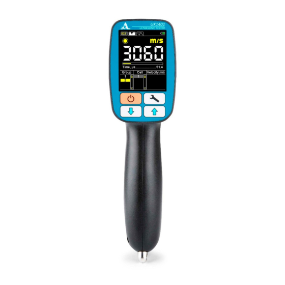
ACOUSTIC Ultrasonic tester UK1401 CONTROL SYSTEMS 1.3 INSTRUMENT DESIGN AND OPERATION PRINCIPLE 1.3.1 Design The instrument represents an electronic unit (Figure 1) enclosed into a plastic case in which two spring-driven ultrasonic transducers (transmitting and receiving) are rigidly mounted. Ultrasonic transducers have cone-type protectors. The ceramic wear proof nozzles are fixed on tops of the protectors. - Page 9 ACOUSTIC Ultrasonic tester UK1401 CONTROL SYSTEMS The lower end face panel of the electronic unit bears the fastener for the belt and an USB Micro B connector used for con- nection to a PC via the USB cable and charging of the built-in accumulator by means of the AC adapter 220 V – USB (Figure 3).
-
Page 10: Operation Principle
ACOUSTIC Ultrasonic tester UK1401 CONTROL SYSTEMS 1.3.2 Operation principle The instrument measures the time interval during which the ultrasonic pulse goes through the inspected object from the transmitting transducer to the receiving transducer. The ultrasonic sound velocity is determined by dividing the distance value between the points of emission and receiving points of ultrasonic waves, by the measured time value. -
Page 11: Screen Oft He Instrument
ACOUSTIC Ultrasonic tester UK1401 CONTROL SYSTEMS - FRONT – measurement of the time interval from the moment the when the signal exceeds the threshold level for the first time (the threshold value is set automatically according to the noise peaks) to the moment when the first half wave of the signal will reach its maximum;... - Page 12 ACOUSTIC Ultrasonic tester UK1401 CONTROL SYSTEMS The icons informing on the presence and strength of the signal, measurement units and numeric value of the measurement result are constantly displayed in all modes. Table 3 contains description of the acoustic contact indicators.
- Page 13 ACOUSTIC Ultrasonic tester UK1401 CONTROL SYSTEMS Display of the instrument in the TIME mode is shown in the Figure 6. Display of the instrument in the VELOCITY mode is shown in the Figure 7. Active tab of the TIME mode...
- Page 14 ACOUSTIC Ultrasonic tester UK1401 CONTROL SYSTEMS Display of the instrument in the CRACK mode is shown in the Figure 8. Display of the instrument in the FRONT mode is shown in the Figure 9. Active tab of the CRACK mode...
-
Page 15: Keyboard
ACOUSTIC Ultrasonic tester UK1401 CONTROL SYSTEMS 1.3.5 Keyboard There are three functional keys and the On/Off key on the keyboard (Figure 10). Main key functions: - The key (ON / OFF) is used to switch On/Off the instrument. ATTENTION: THE INSTRUMENT WILL AUTOMATICALLY SWITCH OFF AFTER 10 MINUTES IN THE STANDBY MODE (NO KEY IS PRESSED, NO MEASUREMENT IS PERFORMED). -
Page 16: Proper Use Of The Instrument
ACOUSTIC Ultrasonic tester UK1401 CONTROL SYSTEMS 2.1 OPERATING RESTRICTIONS The instrument is designed to be operated under conditions listed in Section 1. 1 .2. 2.2 MAKING INSTRUMENT READY FOR OPERATION 2.2.1 Preparation of the Surface The surface of the inspected object must be cleaned of dirt and sand. - Page 17 ACOUSTIC Ultrasonic tester UK1401 CONTROL SYSTEMS - Switch On the instrument. - Select TIME as an observed value. - Place the instrument on the reference sample as indicated in the Figure 12. - Apply pressure on the instrument and fix it.
-
Page 18: Working With The Instrument
ACOUSTIC Ultrasonic tester UK1401 CONTROL SYSTEMS 2.3 WORKING WITH THE INSTRUMENT 2.3.1 SETUP mode The SETUP mode includes the following options: list of the configurable parameters and calibration procedures. All the adjustments will be saved when the instrument is switched Off, or its battery is dead. - Page 19 ACOUSTIC Ultrasonic tester UK1401 CONTROL SYSTEMS Table 4 Menu option Parameter value Description (parameter) Time / Velocity / Mode Selects the measurement mode Crack / Front Accumulation, Qty 1 / 2 / 4 / 8 / 16 / 32 / 64 Sets quantity of accumulations...
- Page 20 ACOUSTIC Ultrasonic tester UK1401 CONTROL SYSTEMS 2.3.1.1 MODE OPTION Select the measurement mode: - TIME – measurement of propagation time of ultrasonic waves in the material; - VELOCITY– measurement of propagation velocity of ultrasonic waves in the material; - CRACK – evaluation of the depth of the crack facing the surface;...
- Page 21 ACOUSTIC Ultrasonic tester UK1401 CONTROL SYSTEMS 2.3.1.3 AGC Option Switching On/Off the automatic control system of the receive path gain. The permissible value range is On / Off. The screen for the AGC option is shown in the Figure 17.
- Page 22 ACOUSTIC Ultrasonic tester UK1401 CONTROL SYSTEMS 2.3.1.4 GAIN Option (only if AGC – OFF) Setting the signal gain. The permissible value range is from 40 to 80 dB. The screen for the GAIN option is shown in the Figure 18 2.3.1.5 FREQUENCY Option...
- Page 23 ACOUSTIC Ultrasonic tester UK1401 CONTROL SYSTEMS To increase the testing quality, try to select the highest possible value of the repetition frequency of the sounding pulses. However, when inspecting the small items (not exceeding several dozen centimeters) with low attenuation, the ultrasonic vibrations in the material will not have time to fade completely by the time when the next sounding signal will be sent to the material, thus it can result in false readings.
- Page 24 ACOUSTIC Ultrasonic tester UK1401 CONTROL SYSTEMS 2.3.1.7 CLEAR MEMORY Option Deletion of the measurement results from the memory. The parameter indicates the filling percentage of the memory with the measurement results. The screen for the CLEAR MEMORY option is shown in the Figure 21.
- Page 25 ACOUSTIC Ultrasonic tester UK1401 CONTROL SYSTEMS 2.3.1.8 CALIBRATION Option The CALIBRATION option is used for the initial calibration of the instrument. The screen for the CALIBRATION option is shown in the Figure 24. To start the calibration, press the "ENTER" button and follow the instructions on the instrument screen (Figure 24).
- Page 26 ACOUSTIC Ultrasonic tester UK1401 CONTROL SYSTEMS 2.3.1.9 DELAY Option The DELAY option is used for setting the hardware time delay. The permissible range of the delay values is from 0 to 20 µs. The screen for the DELAY option is shown in the Figure 25...
- Page 27 ACOUSTIC Ultrasonic tester UK1401 CONTROL SYSTEMS 2.3.1.10 BASE Option The BASE option is used for setting the actual value of the base. The permissible value range is from 149 to 151 mm. The screen for the BASE option is shown in the Figure 26.
- Page 28 ACOUSTIC Ultrasonic tester UK1401 CONTROL SYSTEMS 2.3.1.11 SOUND Option Switching ON/OFF the sound of the instrument. To improve the usability of the instrument, the main events occurring during measurements, adjustments, and when the keys are pressed, are accompanied by sounds.
- Page 29 ACOUSTIC Ultrasonic tester UK1401 CONTROL SYSTEMS 2.3.1.12 LANGUAGE Option Select the interface language of the instrument: - Russian; - English; The screen for the LANGUAGE option is shown in the Figure 28. 2.3.1.13 MEASURING UNITS Option Selecting the measurement units of the system:mm / inches. The screen for the MEASURING UNITS option is shown in the Figure 29.
- Page 30 ACOUSTIC Ultrasonic tester UK1401 CONTROL SYSTEMS 2.3.1.14 BRIGHTNESS Option The value setting range of display brightness is from10 to 100 %. The screen for the BRIGHTNESS option is shown in the Figure 30. 2.3.1.15 CURRENT TIME Option Setting date and time.The screen for the CURRENT TIME option is shown in the Figure 31.
-
Page 31: Time / Velocity Modes
ACOUSTIC Ultrasonic tester UK1401 CONTROL SYSTEMS 2.3.2 TIME / VELOCITY Modes In the TIME / VELOCITY modes the screen is divided into two areas: the upper one displays the information on measurement, the lower displays the information on the results already recorded in the TIME / VELOCITY modes (groups, group cells and measurement results in µs or m/s depending on the selected operation mode) (Figure 32). - Page 32 ACOUSTIC Ultrasonic tester UK1401 CONTROL SYSTEMS 2.3.2.1 Add new last group Use the key to switch to the last group. The user will be prompted to add a new group. If the group is not empty, then the group will be added under the next serial number. If the last group is empty, then the user will be informed and no group will be added (Figure 33).
- Page 33 ACOUSTIC Ultrasonic tester UK1401 CONTROL SYSTEMS 2.3.2.2 RECORDING the Result The measurement results are stored in the cells of the memory. The cells form groups. The groups and the cells in the groups are identified by the serial numbers. The numbering of the groups and the cells in each group is started with “1”.
-
Page 34: Crack Mode
ACOUSTIC Ultrasonic tester UK1401 CONTROL SYSTEMS 2.3.3 CRACK mode The screen in the measurement mode of the crack depth is shown in the Figure 35. In the lower part of the screen the intervals of the ultrasound propagation time are displayed if there is a crack crossing the propagation path of the signal between the ultrasonic transducers to the right, and to the left if there is no crack in the material. -
Page 35: Front Mode
ACOUSTIC Ultrasonic tester UK1401 CONTROL SYSTEMS To measure the crack depth, please perform the following: - Press the instrument for 15 to 20 seconds onto the surface of the object being inspected parallel to the crack about 20 to 30 mm apart. -
Page 36: Transfer Data To Pc
ACOUSTIC Ultrasonic tester UK1401 CONTROL SYSTEMS Select an area without visible defects (cracks, grooves, air pockets, etc.) on the surface of the object to be inspected. The length of the area around the circle perimeter must be at least 180 mm, and height along the moving line must be at least 250 to 400 mm. - Page 37 ACOUSTIC Ultrasonic tester UK1401 CONTROL SYSTEMS Working with numerical data by means of external programs Working with "MS Exсel" Working with a "Notepad" Operation Manual...
-
Page 38: Maintenance
ACOUSTIC Ultrasonic tester UK1401 CONTROL SYSTEMS The maintenance of the instrument includes cleaning the electronic unit from dirt and dust, and charging the battery. 3.1 ACCUMULATOR The rechargeable battery is designed to be operated within a broad temperature range. At negative temperatures the battery capacity is reduced. -
Page 39: Storage
ACOUSTIC Ultrasonic tester UK1401 CONTROL SYSTEMS The instrument should be shelf stored in the hard case included in the delivery kit. The storage conditions shall correspond to GOST 15150-69 (placement category 1). The arrangement of the instruments in warehouses shall enable their free movement by the personnel and unrestricted access to them. -
Page 40: Transportation
ACOUSTIC Ultrasonic tester UK1401 CONTROL SYSTEMS The instrument shall be transported in the hard case included in the delivery kit. The transportation conditions with regard to the impact of the external environmental factors should correspond to the storage conditions (placement category 5) according to GOST 15150-69. - Page 41 ACOUSTIC Ultrasonic tester UK1401 CONTROL SYSTEMS NOTES Operation Manual...
- Page 42 ACOUSTIC Ultrasonic tester UK1401 CONTROL SYSTEMS NOTES Operation Manual...
- Page 43 ACOUSTIC Ultrasonic tester UK1401 CONTROL SYSTEMS Operation Manual...
- Page 44 ACOUSTIC Ultrasonic tester UK1401 CONTROL SYSTEMS ULTRASONIC TESTER UK1401 OPERATION MANUAL Revision: February 2018 Operation Manual...
Need help?
Do you have a question about the UK1401 and is the answer not in the manual?
Questions and answers