
Related Manuals for ACS A1208


Summary of Contents for ACS A1208
- Page 1 ACOUSTIC Ultrasonic thickness gauge A1208 CONTROL SYSTEMS ULTRASONIC THICKNESS GAUGE A1208 OPERATION MANUAL Acoustic Control Systems – ACS Group Saarbrücken, Germany 2019 Operation Manual...
- Page 2 ACOUSTIC Ultrasonic thickness gauge A1208 CONTROL SYSTEMS Operation Manual...
-
Page 3: Table Of Contents
ACOUSTIC Ultrasonic thickness gauge A1208 CONTROL SYSTEMS CONTENTS 1 DESCRIPTION AND OPERATION ..........................6 1.1 Intended use ........................................6 1.1.1 Intended use and range of application ..........................6 1.1.2 Operating conditions ..................................6 1.2 Technical specifications ...................................7 1.3 Arrangement and operation ................................8 1.3.1 Arrangement ......................................8 1.3.2 Operating principle ...................................9... - Page 4 ACOUSTIC Ultrasonic thickness gauge A1208 CONTROL SYSTEMS 2.3 Using the device ......................................18 2.3.1 Work with the device ..................................18 2.3.2 The SETUP mode ....................................18 2.3.3 The MONITORING Mode ................................33 2.3.4 The MEMORY Mode ..................................35 3 MAINTENANCE ................................40 3.1 Battery ............................................40 3.2 Charging the battery ....................................40...
- Page 5 ACOUSTIC Ultrasonic thickness gauge A1208 CONTROL SYSTEMS The present operation manual (hereinafter referred to as the “Manual”) contains technical specifications, description and operating principle of the device as well as information necessary for correct operation of the ultrasonic А1208 thickness gauge (hereinafter referred to as “thick- ness gauge”...
-
Page 6: Description And Operation
ACOUSTIC Ultrasonic thickness gauge A1208 CONTROL SYSTEMS 1.1 THE INTENDED USE 1.1.1 Intended use and range of application The ultrasonic cold-resistant thickness gauge А1208 is used for measuring the thickness of pipe walls (including bends), boilers, cylinders, vessels under pressure, covers and other products from ferrous and nonferrous metals, with smooth or rough and corrosive surfaces, and also products from plastic and other materials with high fading of the ultrasonic sound at a unilateral access to the surface of such products. -
Page 7: Technical Specifications
ACOUSTIC Ultrasonic thickness gauge A1208 CONTROL SYSTEMS 1.2 TECHNICAL SPECIFICATIONS The main technical specifications of the device are given in the Table 1. Table 1 Parameter Value Thickness measurement range (for steel), mm: with the transducer S3567 2.5A0D10CL 0.8 to 300.0 Limits of the absolute permissible inaccuracy of the thickness measurement, mm, max.,... -
Page 8: Arrangement And Operation
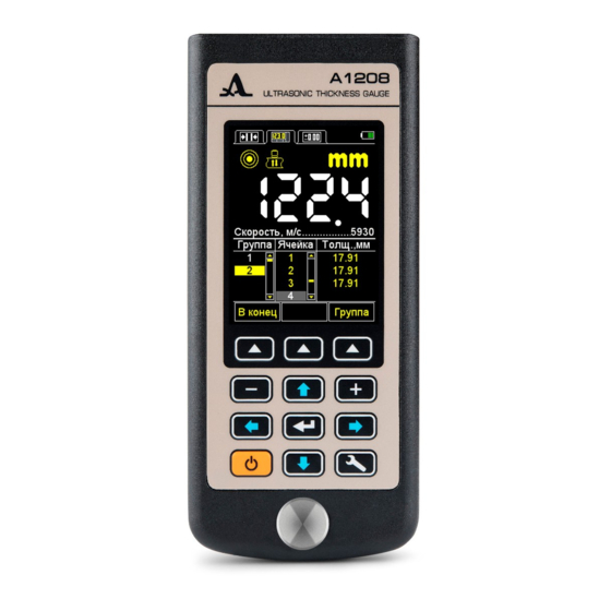
ACOUSTIC Ultrasonic thickness gauge A1208 CONTROL SYSTEMS 1.3 ARRANGEMENT AND OPERATION 1.3.1 Arrangement The thickness gauge consists of an electronic block (Figure 1) with replaceable piezoelectric transducers. The device is connected using cables. Figure 1 The colour TFT display is located in the upper part of the indication panel of the electronic block. It is used to display the measurement results and current information necessary to control the thickness gauge. -
Page 9: Operating Principle
ACOUSTIC Ultrasonic thickness gauge A1208 CONTROL SYSTEMS 1.3.2 Operating principle The operating principle of the А1208 thickness gauge mainly includes the measurement of time needed for the ultrasonic waves to pass the tested object from one surface to another and the subsequent conversion of the measured values into the thickness parameter. -
Page 10: Display Of The Device
ACOUSTIC Ultrasonic thickness gauge A1208 CONTROL SYSTEMS 1.3.4 Display of the device In all operating modes in the upper line of the display the information on the current operating mode of the device and the battery charge level is indicated. - Page 11 ACOUSTIC Ultrasonic thickness gauge A1208 CONTROL SYSTEMS The description of the ultrasonic contact indicators and the measurement method is given in the Table 3. Table 3 Indicator Description Maximum signal. The receiving path amplification setting is minimum. Medium signal. The receiving path amplification setting is medium.
- Page 12 ACOUSTIC Ultrasonic thickness gauge A1208 CONTROL SYSTEMS The display of the instrument in the STANDARD mode is given in Figure 7. The display of the instrument in the MEMORY mode is given in Figure 8. Indicator of the Indicator of the...
-
Page 13: The Device Keyboard
ACOUSTIC Ultrasonic thickness gauge A1208 CONTROL SYSTEMS 1.3.5 The device keyboard The keyboard of the thickness gauge (Figure 9) contains 11 functional keys Figure 9 and the ON/OFF key. The main key functions: The ON/OFF key is used to switch the device on and off. -
Page 14: Intended Use
ACOUSTIC Ultrasonic thickness gauge A1208 CONTROL SYSTEMS 2.1 OPERATIONAL RESTRICTIONS The device is intended for operation under the environmental conditions specified in the Section 1. 1 .2. 2.2 PREPARING THE DEVICE FOR USE 2.2.1 Preparation of the surface Please clean the surface of the object to be tested, remove all dirt and sand and any corrosion, also remove all loose rust and put more liquid than in case of a smooth surface. -
Page 15: Switching The Device On/Off
ACOUSTIC Ultrasonic thickness gauge A1208 CONTROL SYSTEMS 2.2.3 Switching the device On/Off To switch on the device, please press the key The information on the device, its name and the number of the firmware version is displayed on the screen for several seconds (Figure 12). - Page 16 ACOUSTIC Ultrasonic thickness gauge A1208 CONTROL SYSTEMS 2.2.4.2 Setup of the instrument to the parameters of the used transducer The setup is performed in two steps. At the first step the device automatically analyzes the features of the PET. At the second step it is adjusted to these features using the real echo-signal from the calibrator sample built in the device.
- Page 17 ACOUSTIC Ultrasonic thickness gauge A1208 CONTROL SYSTEMS - Remove the transducer from the calibration sample. - Press the key F2 (Ok). If the testing result is positive, the device will change to the measurement mode. If the testing result is negative, the device will return to the the main window of the SETUP mode.
-
Page 18: Using The Device
ACOUSTIC Ultrasonic thickness gauge A1208 CONTROL SYSTEMS 2.3 USING THE DEVICE 2.3.1 Work with the device It is not recommended to slide the operating surface of the PET along the surface of the tested object, if it is not necessary. - Page 19 ACOUSTIC Ultrasonic thickness gauge A1208 CONTROL SYSTEMS The items of the SETUP mode menu are identical for all measurement modes. The corresponding parameters and functions are listed in the Table 4. Table 4 Menu item Parameter value Description Mode Standard/Memory/Permissible...
- Page 20 ACOUSTIC Ultrasonic thickness gauge A1208 CONTROL SYSTEMS The additional menu items of the SETUP mode common to the modes STANDARD and MEMORY and corresponding param- eters and functions are listed in the Table 5. Table 5 Menu item Parameter value...
- Page 21 ACOUSTIC Ultrasonic thickness gauge A1208 CONTROL SYSTEMS 2.3.2.2 Item PT PROBE Active keys: F1 (Test) starting the PT testing procedure and the device setup to the selected transducer; F3 (Open) or enter the transducer reference list to view and select one.
- Page 22 ACOUSTIC Ultrasonic thickness gauge A1208 CONTROL SYSTEMS 2.3.2.3. Item MATERIAL Active keys: F2 to open or to enter the material base, record new and edit the existing materials in the memory and to select the material for further work. The item MATERIAL is shown in the Figure 20.
- Page 23 ACOUSTIC Ultrasonic thickness gauge A1208 CONTROL SYSTEMS Table 6 Intended use Moving in the table of characters Select a character for editing Replace the active character with a character from the table Figure 22 After the replacement, the next character becomes active...
- Page 24 ACOUSTIC Ultrasonic thickness gauge A1208 CONTROL SYSTEMS The library of materials is shown in the Figure 23. If you press the key F2 (Delete) the message “Delete the selected material?” is indicated on the screen. (Figure 24). You can confirm the deletion by pressing F1 (Yes) or cancel it by pressing F3 (No).
- Page 25 ACOUSTIC Ultrasonic thickness gauge A1208 CONTROL SYSTEMS - The message “Data retrieval on the sample with the thickness XXX is in process”, appears on the screen, where ХХХ is the determined sample thickness. - The current result of the velocity measurement is indicated on the screen. When the data retrieval is completed, the velocity value will appear at the screen.
- Page 26 ACOUSTIC Ultrasonic thickness gauge A1208 CONTROL SYSTEMS Saving the velocity values received during the calibration. Active keys: F1 (Yes) save the received velocity value for the material saved in the library (Figure 27) or create a new one (Figure 28).
- Page 27 ACOUSTIC Ultrasonic thickness gauge A1208 CONTROL SYSTEMS 2.3.2.5 Item Monitor Setting the conditions for colour, acoustic and vibration alarm during the measurements. Selecting the alarm conditions: WITHIN means the measurement result is within the set interval; BEYOND means the measurement result is beyond the set interval;...
- Page 28 ACOUSTIC Ultrasonic thickness gauge A1208 CONTROL SYSTEMS 2.3.2.7 Item Limit: to Setting the upper limit of the monitor activation. The permissible values are from 1 to 300 mm. The item LIMIT TO is shown in the Figure 31. Active keys: F2 (Edit.) setting the upper limit of the monitor activation.
- Page 29 ACOUSTIC Ultrasonic thickness gauge A1208 CONTROL SYSTEMS 2.3.2.9 Item CLEAR MEMORY (in the mode MEMORY only) Deleting the measurement results from the memory. As the item parameter the percentage of the memory filling with the measurement results is given. The item CLEAR MEMORY is shown in the Figure 33.
- Page 30 ACOUSTIC Ultrasonic thickness gauge A1208 CONTROL SYSTEMS 2.3.2.10 Item DATA TRANSFER (in the mode MEMORY only) The data file saved in the memory of the thickness gauge can be transferred to a personal computer for the analysis, processing and documentation.
- Page 31 ACOUSTIC Ultrasonic thickness gauge A1208 CONTROL SYSTEMS The item SOUND is shown in the Figure 36. Active keys: F1 (On) Switching the sound indication On F3 (Off) Switching the sound indication Off; Switching the sound indication On/Off. 2.3.2.12 Item VIBRATION Switching the vibration of the device ON/OFF.
- Page 32 ACOUSTIC Ultrasonic thickness gauge A1208 CONTROL SYSTEMS 2.3.2.13 Item LANGUAGE Selecting the language of the device interface: RUSSIAN or ENGLISH. The item LANGUAGE is shown in the Figure 38. Active keys: F1 (Russian) Russian interface settings. F3 (English) English interface settings;...
-
Page 33: The Monitoring Mode
ACOUSTIC Ultrasonic thickness gauge A1208 CONTROL SYSTEMS 2.3.2.14 Item UNITS of MEASUREMENT Selecting the units of measurement: MM or INCHES. The item UNIT of MEASUREMENT is shown in the Figure 39. Active keys: F1 (mm) metric measurement units. The thickness is displayed in mm, the velocity in km/s. - Page 34 ACOUSTIC Ultrasonic thickness gauge A1208 CONTROL SYSTEMS On the Figure 41 you see the device screen in the MONITORING mode when selecting the operating condition AFW WITHIN or BEYOND. If the operating conditions are fulfilled, the measurement result is indicated in red. White color means the condition is not fulfilled.
-
Page 35: The Memory Mode
ACOUSTIC Ultrasonic thickness gauge A1208 CONTROL SYSTEMS 2.3.4 MEMORY mode In the MEMORY mode the screen in divided in two windows. In the upper window you see the information on the measure- ment similar to the MONITORING mode (thickness, signal level, measurement method). In the lower part the information on the previously saved results is indicated (groups, cells of groups and results). - Page 36 ACOUSTIC Ultrasonic thickness gauge A1208 CONTROL SYSTEMS 2.3.4.2 Save results Measurement results are stored in the device memory in cells, which form groups. Groups and cells in groups are identified by serial numbers. Groups and cells in each group are numbered, started with number ONE.
- Page 37 ACOUSTIC Ultrasonic thickness gauge A1208 CONTROL SYSTEMS Note: as a matter of fact, the result remains in the device memory until a new value is recorded in the selected cell. To return to the view mode, without changing the value recorded in the cell please press Perform the measurement.
- Page 38 ACOUSTIC Ultrasonic thickness gauge A1208 CONTROL SYSTEMS Please perform the testing again after thorough cleaning the contact place from corrosion. Always remove rough edges and corrosion from the TO, as this increases the measurement accuracy and allows to increase the service life of the PT.
- Page 39 ACOUSTIC Ultrasonic thickness gauge A1208 CONTROL SYSTEMS When measuring the thickness of objects with a double convex surface ensure the testes object is in contact with the middle of the transducer operating surface. When you deal with TO with rough or uneven surface combined transducers offer more advantages compared to separat- ed-combined transducers.
-
Page 40: Maintenance
ACOUSTIC Ultrasonic thickness gauge A1208 CONTROL SYSTEMS The maintenance of the device includes cleaning of the electronic unit from dirt and dust and loading the battery. 3.1 BATTERY The device battery can be used in a wide temperature range from - 30° to + 50 ºС. In the lower temperature range the battery capacity is app. -
Page 41: Storage
ACOUSTIC Ultrasonic thickness gauge A1208 CONTROL SYSTEMS Please store the device in the rigid suitcase from the scope of delivery. The storage conditions must conform with the relevant international standards (see chapter 1.3). Please store the device on a shelf. -
Page 42: Transportation
ACOUSTIC Ultrasonic thickness gauge A1208 CONTROL SYSTEMS Please transport the device in the rigid suitcase from the scope of delivery. Packaged instruments can be transported at any distances and with any kind of vehicle without speed restrictions. Packaged instruments should be properly and steadily fasted during transportation. When transported in open vehicles the instruments shall be protected from rain and water splashes. - Page 43 ACOUSTIC Ultrasonic thickness gauge A1208 CONTROL SYSTEMS The propagation velocity of longitudinal ultrasonic waves in some materials are specified in the Table А. 1 Table A.1 Material Velocity, m/s Material Velocity, m/s aluminium 6260 concretes 2000 – 5400 aluminum alloy D16T...
- Page 44 ACOUSTIC Ultrasonic thickness gauge A1208 CONTROL SYSTEMS ▼ Table A.1 Material Velocity, m/s Material Velocity, m/s osmium 5478 mica 7760 plumbum 2160 organic glass 2550 silver 3600 silicious glass 5500 glass-ceramics 6740 steel Ch15Н15GS 5400 steel 20 GSNDM 6060 steel St3...
- Page 45 ACOUSTIC Ultrasonic thickness gauge A1208 CONTROL SYSTEMS NOTES Operation Manual...
- Page 46 ACOUSTIC Ultrasonic thickness gauge A1208 CONTROL SYSTEMS NOTES Operation Manual...
- Page 47 ACOUSTIC Ultrasonic thickness gauge A1208 CONTROL SYSTEMS Operation Manual...
- Page 48 ACOUSTIC Ultrasonic thickness gauge A1208 CONTROL SYSTEMS ULTRASONIC THICKNESS GAUGE A1208 OPERATION MANUAL Revision: February 2019 Operation Manual...
Need help?
Do you have a question about the A1208 and is the answer not in the manual?
Questions and answers