ACS ALCOLOCK LR Installation Manual
Alcohol interlock
Hide thumbs
Also See for ALCOLOCK LR:
- Instruction manual (4 pages) ,
- Troubleshooting manual (12 pages)
Table of Contents
Advertisement
Quick Links
Advertisement
Table of Contents

Related Manuals for ACS ALCOLOCK LR


Summary of Contents for ACS ALCOLOCK LR
- Page 1 Installation Manual...
- Page 2 60 International Boulevard Toronto, Ontario M9W 6J2 CANADA acs-corp.com ALCOLOCK, ALCOHOL COUNTERMEASURE SYSTEMS, ACS, INTERTRACK and The Molly are trademarks of Alcohol Countermeasure Systems (International) Inc. and are used under license. Alcohol Countermeasure Systems is the trading style of Alcohol Countermeasure Systems Corp.
-
Page 3: Table Of Contents
CONTENTS ALCOLOCK LR alcohol interlock – product profile ........5 The ALCOLOCK LR device installation manual .......... 5 How to read this manual ................ 6 Other required manuals ................. 6 Parts and equipment supplied by ACS (the Service Provider) ................7 Tools and equipment supplied by the Service Centre (service facility) ................ - Page 4 Input odometer reading..............58 22.5 Performing an ITE removal transaction ..........59 22.6 Removing ECU and restoring the vehicle ..........60 23.0 Recycling the ALCOLOCK LR device............61 24.0 Tampering ..................61 24.1 Signs of tampering ................61 24.2 Examples of tampering – before and after ..........62 24.3...
- Page 5 Appendixes ....................65 Appendix 1: Tamper report ....................65 Appendix 2: Glossary ...................... 66 Appendix 3: LR circuit diagram (low-current vehicles) ............ 69 Appendix 4: LR circuit diagram (with external relay) ............70 Installation Manual...
-
Page 6: Alcolock Lr Alcohol Interlock - Product Profile
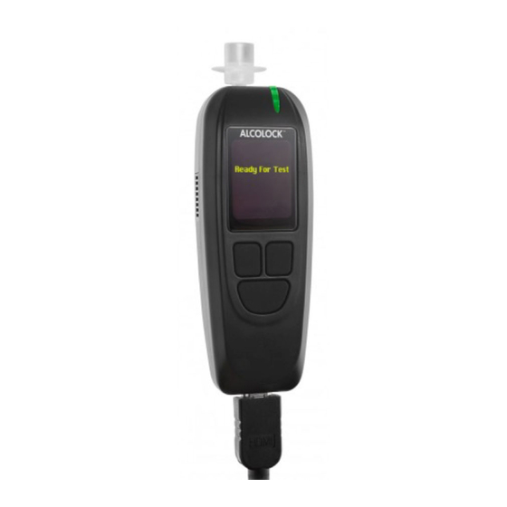
The ALCOLOCK LR alcohol interlock device will never cause the vehicle engine to stop. The ALCOLOCK LR device consists of a Handset (HS) to conduct breath alcohol tests, and an Electronic Control Unit (ECU) that is connected with the power and control circuits of the vehicle. -
Page 7: How To Read This Manual
How to read this manual • For installation of the ALCOLOCK LR device, read sections 5.0 to 20.0 of this manual, in the order provided • For wiring diagrams (with and without the external relay), refer to appendix 3 and 4 of this manual •... -
Page 8: Parts And Equipment Supplied By Acs (The Service Provider)
Parts and equipment supplied by ACS (the Service Provider) This section lists parts supplied by ACS, which are required by the Service Centre for the alcohol interlock program, including installation, monitoring, calibration and removal of the ALCOLOCK LR device. Contact ACS to order the following parts (for contact information, refer to acs-corp. - Page 9 Front clip with brass Enclosure 58-000529 insert 65-000070 Rear clip Enclosure 58-000527 Screw Fastening rear and front clip Plastic plug Covering screw (front clip) 45-000129 58-000528 Tamper-proof label Covering plastic plug (front clip) Accessories and consumable items for alcohol interlock program: Part # Part Description...
-
Page 10: Tools And Equipment Supplied By The Service Centre (Service Facility)
Tools and equipment supplied by the Service Centre (service facility) This section lists parts supplied by the Service Centre, which are required for the installation, monitoring and removal the ALCOLOCK LR device. Power tools • Portable reversible battery operated drill with bits •... -
Page 11: Installation Overview
Installation overview To install the ALCOLOCK LR device, complete the following steps in the order provided in this manual. • Inspecting the vehicle electrical system • Mounting the ECU, alarm horn, and (if required) alarm flasher • (If required) Locating the tach signal (using DTS, if applicable) •... -
Page 12: Inspecting The Vehicle Charging System
ATTENTION! The alarm horn is intended for installation on vehicles with +12 volt electrical systems only. 1. Locate an alarm horn mounting position under the hood. Ensure that there is sufficient clearance, so that closing the hood does not damage the hood or the alarm horn. ALCOLOCK LR... -
Page 13: Mounting The Alarm Flasher (If Required)
2. Position the alarm horn facing downwards. This is to protect the alarm horn opening from contaminants, such as water leakage and dust. 3. Mount the alarm horn bracket to the vehicle. NOTE: Always use existing hardware and holes to minimize vehicle modification. 4. -
Page 14: Locating The Tachometer Signal Wire
This section will provide an overview and steps for the connection of ECU cable, alarm horn and the alarm flasher (if required). ATTENTION! • Do not solder or apply heat shrinks or tamper proof labels until all wires have been attached, and post installation testing has been performed • The ALCOLOCK LR alcohol interlock is a low current device. Use a supplied external relay on vehicles with high-current starter circuits (above 2 amps) • Do not connect the ECU cable to the ECU until instructed. This may result in damage to the ECU • Do not use the vehicle fuse panel for the wire connections. In most cases, it is easily accessible and vulnerable to tampering • To avoid damaging the ECU, always connect the ground wires to the vehicle first • Each connection must be as neat and secure as possible – use solder point connections and supplied heat shrinks ALCOLOCK LR... -
Page 15: Ecu Cable-Wire Summary
• Do not use butt or clip connectors to seal wiring, as this may lead to corrosion and intermittent power • Use supplied, heat shrinks or tamper resistant labels on all solder connections. Refer to section 20.0 of this manual • Use supplied tie wraps to neatly incorporate wires into the vehicle wire loom. Keep wires away from vehicle components that move, or that become excessively hot 14.1 ECU cable-wire summary The following table lists the wires from the ECU cable (13-001102), for basic reference. NOTE: Refer to the appendix 3 and 4 at the back of this manual for wiring diagrams (with and without the external relay). -
Page 16: Ecu Wire-Connection Steps
10. Using the computer-safe test probe, locate the wire coming from the ignition switch and going to the starter relay or solenoid (depending on the vehicle make). This wire supplies the start signal. 11. Cut the wire (that supplies the start signal). Expose 3/4” of wire from each cut end. ALCOLOCK LR... -
Page 17: Alarm Horn Wire-Connection Steps
12. Move the vehicle ignition switch to the start position – the starter must not engage. ATTENTION! • The ALCOLOCK LR alcohol interlock is a low current device. Use an external relay on vehicles with high-current starter circuits (above 2 amps) • Refer to appendix 4 at the back of this manual for the wiring diagram that includes the external relay 13. Connect ECU wire 10 (Blue-Yellow) to the cut end of the wire coming from the ignition switch. 14. Connect ECU wire 9 (Light Blue) to the cut end of the wire going to the starter relay or solenoid (depending on the vehicle make). -
Page 18: Alarm Flasher Wire-Connection Steps (If Required)
3. Connect ECU wire 11 (Violet) to the ECU wire 1 (Red). 4. Use supplied tie wraps to neatly incorporate the retest alarm wires with the vehicle wire loom. Keep wires away from vehicle components that move, or that become excessively hot. ALCOLOCK LR... -
Page 19: Tachometer Wire-Connection Steps
14.6 Tachometer wire-connection steps NOTE: • Skip this section if the vehicle tach reading will be obtained using vehicle OBD-II • Section 13.0 provides instructions for locating the tach signal wire from under the hood Attach the vehicle tach signal wire to ECU wire 2 (Green). Use supplied tie wraps to neatly incorporate the tach connection with the vehicle wire loom. -
Page 20: Attaching The Hs And Ecu
Before attaching the HS and the ECU, the ECU must be mounted and all ECU wires must be connected. ATTENTION! Do not solder or apply heat shrinks or tamper-proof labels until all wires have been attached and post-installation testing has been performed. 1. Connect the ECU cable (13-001102) to the ECU main input. The cable clicks into place and the ECU beeps. ALCOLOCK LR... - Page 21 000028). 16.0 HS install procedure and ITE install transaction After the ALCOLOCK LR device has been connected to the vehicle, perform the HS install procedure by following the steps that appear on the HS screen. The purpose of the HS install procedure is to activate the device and test device functions.
-
Page 22: Hs Install Procedure And Ite Install Transaction
Remaining in any screen for 5 minutes will exit the procedure • Refer to the ITE instruction manual for the install transaction procedure 16.1 Performing the HS install procedure 1. Press any navigation button to power up the device. Wait… is briefly displayed as the HS powers up. ALCOLOCK LR... - Page 23 Handset Not Activated is automatically displayed. 2. Press and hold the left button to enter Menu. 3. In Menu, press Prev or Next to scroll to Service, then press Select. 4. Input the daily 4-digit service code (press + or – to change a digit, and press Select to move to the next digit).
- Page 24 ECU Speaker is displayed. The HS LED light is off. The ECU beeps and the pitch descends for three beeps. After this sequence, OK is displayed. 9. If the test is successful, press OK. If the ECU does not beep, or “OK” is not displayed, press and hold the bottom button to exit the procedure. Restart the procedure and if the problem persists, check the ECU cable connections and replace the ECU. ALCOLOCK LR...
- Page 25 VEHICLE Alarm is displayed. The HS LED light is off. The alarm horn sounds and (if used) the alarm flasher flashes. After the alarm horn sounds three times and the alarm flasher flashes three times (if used), OK is displayed. 10.
- Page 26 14. Turn the key to the position. The vehicle engine will start because the Relay is On. Start Engine is briefly displayed. Continue to the next section. 16.2 OBD-II Select 1. OBD-II SELECT is automatically displayed. For conventional / non-hybrid vehicles, the ALCOLOCK LR device must obtain a tach (rpm) reading from under the hood. For non-hybrid vehicles with OBD-II, a tach signal may be obtained by connecting the ECU to vehicle OBD-II. For hybrid vehicles, tach is not available – an OBD-II speed threshold is already programmed into the software. The ECU must be connected to the vehicle OBD-II source. ALCOLOCK LR...
-
Page 27: Obd-Ii Select
2. Press Select to scroll to one of the 3 following options: OBD / TACH – for non-hybrid vehicles connected to OBD-II. OBD / SPEED – for hybrid vehicles connected to OBD-II. NO OBD – for vehicles not connected to OBD-II, and instead connected to a direct tach source under the hood. -
Page 28: Obd / Tach
TACH is displayed, along with the following: • Idling – the vehicle engine rpm reading • Idle Point – reset to 0.5 x the Idling engine rpm • Run Point – reset to 1.5 x the Idling engine rpm ALCOLOCK LR... -
Page 29: Obd Speed
Next is displayed at the bottom-left of the screen. 3. If the tach thresholds are correct, press Next (otherwise press Set Tach until a correct tach threshold is obtained). After Next is pressed, ACCELERATE is displayed, along with the following: Idling –... -
Page 30: No Obd
Idling – the vehicle engine rpm reading If the “Idling” rpm reading is lower than the “Idle Point” rpm value on the second line, “Stopped” will be displayed instead of “Idling”. If the “Idling” rpm reading is higher than the “Run Point” rpm value on the third line, “Running” will be displayed instead of “Idling”. If the rpm reading on the first line is not set to “Idling”, check the tach source and the ECU connection. A new tach source may be required. If the problem continues, obtain the tach signal using a digital tach sensor (DTS). The ECU or HS may need to be exchanged. • Idle Point – a preset rpm threshold value • Run Point – a preset rpm threshold value The initial “Idle Point” and “Run Point” values may vary, depending on the vehicle. ALCOLOCK LR... - Page 31 1. Check that the Idling rpm reading reflects the reading on the dashboard rpm gauge. 2. If the Idling rpm reading is acceptable, press Set Tach to reset the rpm thresholds. After “Set Tach” is pressed, the “Idling” rpm reading (on the first line) is used to reset the “Idle Point” and “Run Point” tach thresholds (the second and third lines). TACH is displayed, along with the following: •...
-
Page 32: Input Odometer Reading
1. Disconnect the HS from the HS cable. 2. Using the USB cable (79-008958), connect the HS to the UCS or DS and perform an ITE install transaction. NOTE: Refer to the ITE application manual for the install transaction procedure. ALCOLOCK LR... -
Page 33: Post-Installation Testing
With the vehicle in park or neutral, turn on the vehicle engine for a short period. NOTE: Refer to the instruction manual for more information about using the ALCOLOCK LR device. 18.0 Attaching the security enclosure Attach the security enclosure only after doing the following: •... - Page 34 6. Insert the plastic plug (58-000528) into the screw hole of the rear clip, covering the screw. 7. Apply a tamper-proof label (65-000070) to the rear clip, over the glossy rectangular area that surrounds the plastic plug. ALCOLOCK LR...
-
Page 35: Attaching The Gps Antenna (If Required)
19.0 Attaching the GPS antenna (If required) The GPS module (04-000001) is attached separately to the ECU. The GPS module consists of a cable plug and an antenna with an adhesive strip. 1. Attach the GPS cable plug onto the communication port at the bottom of the ECU. - Page 36 (3M brand or equivalent) and a tamper proof label. 7. Reinstall all vehicle panels. 8. Perform a final visual inspection. Ensure that the vehicle is returned to its original appearance. *You have completed the installation of the ALCOLOCK LR alcohol interlock device* ALCOLOCK LR...
-
Page 37: Hs Monitor Procedure And Ite Monitor Transaction
21.0 HS monitor procedure and ITE monitor transaction During routine monitoring appointments, perform the HS monitor procedure by following the steps that appear on the HS screen. The purpose of the HS monitor procedure is to test device functions. At the end of the HS monitor procedure, detach the HS from the vehicle and connect it to a PC, via a Download Station (79-008954) or Universal Calibration Station (79-007303), to perform an ITE monitor transaction. -
Page 38: Performing The Hs Monitor Procedure
3. In Menu, press Prev or Next to scroll to Service, then press Select. 4. Input the daily 4-digit service code (press + or – to change a digit, and press Select to move to the next digit). 5. After setting the last digit, press Select. ALCOLOCK LR... - Page 39 6. With the correct code entered, press Accept; otherwise, press Correct to re-enter the service code, or press Cancel to return to Main Menu. 7. In the SERVICE menu, press Prev or Next to scroll to Monitor, then press Select. Wait is briefly displayed as the monitor procedure loads.
- Page 40 11. If the test is successful, select OK. If the retest alarm does not flash (only if not used), or “OK” is not displayed, press and hold the bottom button to exit the procedure. Restart the procedure and if the problem persists, check the ECU cable and alarm flasher connections and replace the ECU and alarm flasher. Turn Ignition ON is displayed. Ignition: OFF and Relay: OFF are displayed. 12. Turn the ignition key to the position. The vehicle engine cannot be started because the Relay is OFF. ALCOLOCK LR...
- Page 41 Turn Ignition OFF is displayed. Ignition: ON and Relay: OFF are displayed. 13. Turn the key to the position. Turn Ignition ON is displayed. Ignition: OFF and Relay: ON are displayed. ATTENTION! • Before starting the ignition, ensure that the vehicle is in the park or neutral position, with parking brake engaged, to prevent the vehicle from moving • Leaving the vehicle engine on for too long will cause the vehicle alarm horn to sound start 14. Turn the key to the position.
-
Page 42: Obd-Ii Select
OK. Read only one of the following sections of this manual, based on the step 2 selection: • OBD / TACH – section 21.2.1 • OBD / SPEED – section 21.2.2 • NO OBD – section 21.2.3 ALCOLOCK LR... -
Page 43: Obd / Tach
21.2.1 OBD / TACH NOTE: Read this section for non-hybrid vehicles where the tach was obtained through OBD-II. After selecting the OBD / TACH option in the previous screen, TACH is displayed, along with the following: • Idling – the vehicle engine rpm reading If the “Idling” rpm reading is lower than the “Idle Point” rpm value on the second line, “Stopped” will be displayed instead of “Idling”. -
Page 44: Obd Speed
21.2.2 OBD Speed NOTE: Read this section for hybrid vehicles only. After selecting the OBD/SPEED option in section 21.2 “OBD Select”, CHECK SPEED is displayed. Speed is displayed at 0, however the value may slightly fluctuate. ALCOLOCK LR... -
Page 45: No Obd
The OBD-II speed threshold is already programmed into the software and does not need to be set. Do not move the vehicle. 1. Press OK to proceed. If the speed is correct, Turn Off Engine is displayed. 2. Turn the key to the position. - Page 46 4. Press the accelerator pedal and steadily increase the engine rpm to a point slightly above the Run Point rpm threshold value on the third line. (This is to validate the Run Point rpm threshold value that was reset in step 3.) ALCOLOCK LR...
-
Page 47: Input Odometer Reading
If the Run Point value is correct, Turn Off Engine is automatically displayed after the engine rpm exceeds the value on the third line. 5. Turn the key to the position. (Press Cancel to return to the Monitor menu.) Continue to the next section. 21.3 Input odometer reading After the tach or speed threshold has been set, Odometer is... -
Page 48: Device Removal Overview
The purpose of the HS removal procedure is to test device functions. At the end of the HS monitoring procedure, detach the HS from the vehicle and connect it to a PC, via a Download Station (79-008954) or Universal Calibration Station (79-007303), to run an ITE removal Transaction. ALCOLOCK LR... -
Page 49: Performing The Hs Removal Procedure
ATTENTION! • Complete the HS removal procedure on the HS display before performing an ITE removal transaction • Before beginning the procedure ensure that there is sufficient ventilation for vehicle exhaust fumes. Failure to do so may cause injury • Before beginning the procedure ensure that the vehicle is in the park or neutral position, with parking brake engaged, to prevent the vehicle from moving USING HANDSET BUTTONS: HS screen options will appear at the bottom of the display (at the left, right or bottom-centre). Press the left, right or bottom navigation button to select a corresponding screen-command option. NOTE: •... - Page 50 Select to move to the next digit). 5. After setting the last digit, press Select. 6. With the correct code entered, press Accept; otherwise, press Correct to re-enter the service code, or press Cancel to return to Main Menu. ALCOLOCK LR...
- Page 51 7. In the SERVICE menu, press Prev or Next to scroll to Removal, then press Select. Wait is briefly displayed as the removal procedure loads. NOTE: REMOVAL will display at the top of the screen during the HS removal procedure. 8. HANDSET LED & Buzzer is displayed. The HS LED light flashes from green to amber.
- Page 52 12. Turn the ignition key to the position. The vehicle engine cannot be started because the Relay is OFF. Turn Ignition OFF is displayed. Ignition: ON and Relay: OFF are displayed. 13. Turn the key to the position. ALCOLOCK LR...
-
Page 53: Obd-Ii Select
Turn Ignition ON is displayed. Ignition: OFF and Relay: ON are displayed. ATTENTION! • Before starting the ignition, ensure that the vehicle is in the park or neutral position, with parking brake engaged, to prevent the vehicle from moving • Leaving the vehicle engine on for too long will cause the vehicle alarm horn to sound start 14. Turn the key to the position. The vehicle engine will start because the Relay is On. Start Engine is briefly displayed. Continue to the next section. 22.3 OBD-II Select 1. -
Page 54: Obd / Tach
NOTE: Read this section for non-hybrid vehicles where the tach was obtained through OBD-II. After selecting the OBD / TACH option in the previous screen, TACH is displayed, along with the following: • Idling – the vehicle engine rpm reading ALCOLOCK LR... - Page 55 If the “Idling” rpm reading is lower than the “Idle Point” rpm value on the second line, “Stopped” will be displayed instead of “Idling”. If the “Idling” rpm reading is higher than the “Run Point” rpm value on the third line, “Running” will be displayed instead of “Idling”. If the rpm reading on the first line is not set to “Idling”, check ECU OBD-II connection. If the problem continues, obtain the tach signal from a location under the hood. Refer to section 13.0 and 14.6 of this manual. The ECU and HS may need to be exchanged. • Idle Point – a preset rpm threshold value • Run Point – a preset rpm threshold value The initial Idle Point and Run Point values may vary, depending on the vehicle. 1. Check that the Idling rpm reading reflects the reading on the dashboard rpm gauge.
-
Page 56: Obd Speed
Select”, CHECK SPEED is displayed. Speed is displayed at 0, however the value may slightly fluctuate. The OBD-II speed threshold is already programmed into the software and does not need to be set. Do not move the vehicle. ALCOLOCK LR... -
Page 57: No Obd
1. Press OK to proceed. If the speed is correct, Turn Off Engine is displayed. 2. Turn the key to the position. (Press Cancel to return to the Removal menu.) Skip section 22.3.3 and continue to section 22.4 to input the odometer reading. - Page 58 4. Press the accelerator pedal and steadily increase the engine rpm to a point slightly above the Run Point rpm threshold value on the third line. (This is to validate the Run Point rpm threshold value that was reset in step 3.) ALCOLOCK LR...
-
Page 59: Input Odometer Reading
If the Run Point value is correct, Turn Off Engine is automatically displayed after the engine rpm exceeds the value on the third line. 5. Turn the key to the position. (Press Cancel to return to the Removal menu.) Continue to the next section. 22.4 Input odometer reading After the tach or speed threshold has been set, Odometer is... -
Page 60: Performing An Ite Removal Transaction
4. If a retest alarm was used (for the hearing impaired) disconnect ECU wire 6 (Pink) from the red (positive) wire of the retest alarm and disconnect ECU wire 11 (Violet) from ECU wire 1 (Red). ALCOLOCK LR... -
Page 61: Recycling The Alcolock Lr Device
16. Perform a final inspection. Ensure that vehicle is returned to its original appearance. 23.0 Recycling the ALCOLOCK LR device Following the removal, devices (ECU, HS, or both) that are functioning correctly will remain at the Service Centre. Devices in need of repair, or at the end of their service life, must be returned to ACS. -
Page 62: Tampering
ATTENTION! Instances of tampering are not limited to these areas, and you must check the entire device wiring assembly and all components for signs of tampering. Before tampering After tampering Tamper resistant label over wiring: NOTE: Look for any traces of the VOID marking left under a removed seal. Tamper resistent label over vehicle grounding: ALCOLOCK LR... - Page 63 Tamper seal over security enclosure (front clip): HS screw plugs (x4): Installation Manual...
-
Page 64: Tamper Report Procedure
The below table lists interlock events that are associated with tampering. If any interlock event appears in the event log, the client must fill out an occurrence report that provides an explanation for that event. For more information refer to the ALCOLOCK LR compliance manual and troubleshooting manual. ATTENTION! •... - Page 65 The service technician must resolve any matters surrounding the functioning of the ALCOLOCK LR device. NOTE: If the event was not caused by a mechanic, it must be documented in the occurrence report.
-
Page 66: Appendixes
Tamper Type: Date of Tamper: Time of Tamper: Comments: Violation Type Indicate all Violations Power Off/ Power On Recall Picture Start Violation Picture Other Picture Other FAX (1) COPY OF THIS Alcohol Countermeasure Systems ALCOLOCK @________________ FORM TO: ALCOLOCK LR... -
Page 67: Appendix 2: Glossary
(HS or ECU): Performed on ITE when an installed HS or ECU requires replacement. handset (HS): Part of the ALCOLOCK LR device that is used to conduct breath alcohol tests and communicate with the driver. Installation Manual... - Page 68 INTERTRACK Enterprise (ITE): A proprietary computer-software application, and its suite of applications, developed by ACS and provided as a service over the internet for use by Service Providers, Service Centres, and others authorized by ACS for the delivery of Program Services – including any upgrades thereto.
- Page 69 The tach signal (rpm) value at which the vehicle engine is on with the accelerator pedal pressed. During the HS install, monitor and removal procedures, the ALCOLOCK LR device sets the vehicle-run threshold at 1.5 x idling engine rpm.
-
Page 70: Appendix 3: Lr Circuit Diagram (Low-Current Vehicles)
Appendix 3: LR circuit diagram (low-current vehicles) ALCOLOCK LR... -
Page 71: Appendix 4: Lr Circuit Diagram (With External Relay)
Appendix 4: LR circuit diagram (with external relay) Installation Manual... - Page 72 INM-ENG-60-000373-A © 2012...
Need help?
Do you have a question about the ALCOLOCK LR and is the answer not in the manual?
Questions and answers