ACS Alcolock WR3 Instruction Manual
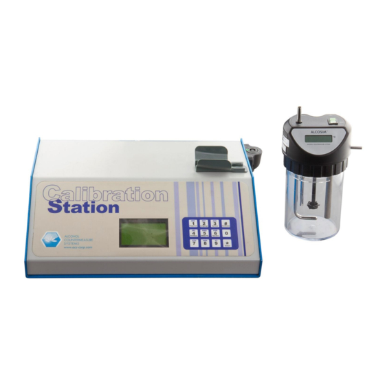
Calibration station
Hide thumbs
Also See for Alcolock WR3:
- Troubleshooting manual (16 pages) ,
- Service manual (4 pages) ,
- User manual (28 pages)
Table of Contents
Advertisement
Quick Links
Advertisement
Table of Contents

Related Manuals for ACS Alcolock WR3


Summary of Contents for ACS Alcolock WR3
- Page 1 WR3 Calibration Station Instruction Manual...
- Page 2 Toronto, Ontario M9W 6J2 CANADA acs-corp.com ALCOLOCK, ALCOSIM, ALCOHOL COUNTERMEASURE SYSTEMS, ACS, INTERTRACK and The Molly are trademarks of Alcohol Countermeasure Systems (International) Inc. and are used under license. Alcohol Countermeasure Systems is the trading style of Alcohol Countermeasure Systems Corp ©...
-
Page 3: Table Of Contents
Contents Introduction ................................1 ACS part numbers ..............................2 Part descriptions ..............................2 ALCOSIM breath alcohol simulator ............................2 Calibration Station (CS) ................................ 2 ITE ......................................2 Alcohol reference solution ..............................2 ALCOSIM breath alcohol simulator diagram ...................... 3 CS diagram ................................4 Unpacking, inspection and operating check ...................... -
Page 5: Introduction
1.0 Introduction The ACS Calibration Station (CS) is diagnostic equipment designed to establish and maintain compliance of the ALCOLOCK WR3 alcohol interlock Handset (HS). The following are the main components required for calibration: Calibration Station (CS) ALCOSIM breath alcohol simulator ... -
Page 6: Acs Part Numbers
2.0 ACS part numbers The following section lists parts supplied by ACS that are required by the Service Centre for calibration of the ALCOLOCK WR3 device. Contact ACS to order the following parts (for contact information, refer to acs-corp.com). Product... -
Page 7: Alcosim Breath Alcohol Simulator Diagram
4.0 ALCOSIM breath alcohol simulator diagram ALIBRATION TATION NSTRUCTION ANUAL... -
Page 8: Cs Diagram
5.0 CS diagram CS front view CS rear view HS cradle CPC connector (for HS) Display Option / number pad Communication port (for ALCOSIM) Air outlet Main power switch Main power input... -
Page 9: Unpacking, Inspection And Operating Check
6.0 Unpacking, inspection and operating check ATTENTION! Note the following before unpacking any components or adding water to the ALCOSIM simulator: Do not switch on the ALCOSIM simulator and CS until instructed Do not plug in the ALCOSIM simulator and CS power cables until instructed ... -
Page 10: Detailed Operation
7.0 Detailed operation ALCOSIM simulator setup ATTENTION! Note the following before adding solution to the ALCOSIM simulator: Do not switch on the ALCOSIM simulator and CS until instructed Do not plug in the ALCOSIM simulator and CS power cable until instructed ... -
Page 11: Cs Setup
The propeller begins turning and the solution automatically begins heating up to 34°C. This takes up to 20 minutes. The ALCOSIM screen displays the temperature. Connect a plastic tube from the ALCOSIM air outlet (side) to the mouthpiece, setting the mouthpiece as follows: To ALCOSIM air outlet (side) NOTE: ... - Page 12 Using cable 79-007850, connect the ALCOSIM communication port to the CS port. ATTENTION! The white dots on the CS plug and port must align, and the plug will click into place Ensure that the pegs align; the plugs are brittle Place the HS into the CS cradle.
-
Page 13: Calibrating The Hs
Calibrating the HS NOTE: There are different versions of firmware that display slightly different messages. This manual uses the newest version, with the older version in parentheses { }, where applicable. Switch on the CS, at the back. The CS initializes and displays the following: ... -
Page 14: Successful Testing
Simulator: Wet Bath is displayed. Press the right button to select OK. Standard: 50mg% is displayed. Press the right button to select OK. {The older firmware does not support this option – continue to the next step.} The HS beeps and displays a Ready {Wait} message. The CS LED is solid amber. The CS displays the message: Wait 2:00 for Handset to warm up. -
Page 15: Troubleshooting
Perform a CS download. download. Exchange HS for a new one and return No access Real time clock cannot be read. the old to ACS. Real time clock is not functioning Exchange HS for a new one and return Not ticking properly. -
Page 16: Hs Error Messages
Calibration Failed some way. The HS LED is flashing red. assembled. Recommence calibration procedure. If the problem persists, send the HS back to ACS for repair. CS states The CS has 4 states prior to calibration: State LED or tone... -
Page 17: Pump Test
Pump test This feature allows the user to see if the pump is functioning properly. This will help in diagnosing problems that may be encountered during routine testing. To perform a pump test, press the # button from the main screen to access the main menu. Using the # button, scroll to the Pump Test item in the menu. -
Page 18: Speaker
Once the lot and serial number have been entered, select Enter using the # button and * to select and return to the main menu. To return to the main display screen, scroll through the menu options, pressing the # button, and select Exit by pressing the * button. - Page 19 IRM-ENG-60-000323-A © 2012...
Need help?
Do you have a question about the Alcolock WR3 and is the answer not in the manual?
Questions and answers