Table of Contents
Advertisement
Advertisement
Table of Contents

Subscribe to Our Youtube Channel
Related Manuals for Colorlight Z6 Super Controller


Summary of Contents for Colorlight Z6 Super Controller
- Page 1 Z6 Super Controller...
-
Page 2: Table Of Contents
Content 1 Overview ................................1 2 Appearance ...............................1 3 Signal Connection ............................3 4 LEDVISION Installation ...........................3 5 Parameter Configuration ..........................4 5.1 Detect Sender and Receiving Card ......................4 5.2 LED Screen Setting ............................5 5.2.1 Sending Device Setting ........................6 5.2.2 Screen Parameters Setting ......................13 5.2.3 Connection Parameters Setting ..................... -
Page 3: Overview
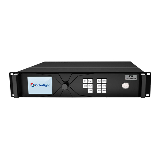
1 Overview Z6 Super Controller is a professional LED display controller. As video splicer, processor and sender in one combined, Z6 has 4K video input capability, UHD and HDR images processing and transmission. Z6 can be applied to high-end rental display and high resolution LED display perfectly. - Page 4 OK:Enter key ESC: Escape current operation or selection Function keys Bright: Brightness options Black: Blank screen Lock: Lock keys PIP: PIP switch Selection keys Freeze: Freeze screen DVI/HDMI/SDI1/SDI2: video source selection Back Panel Input Interface 2 3G-SDI inputs HDMI HDMI2.0 input 4 DVI inputs Output Interface Gigabit Ethernet...
-
Page 5: Signal Connection
3 Signal Connection 4 LEDVISION Installation Please download the installation package of the LEDVISION software from Colorlight’s official website, and complete the installation according to the diagrams shown below. ① Run the software package, and select [English] for installer language. Click [OK] to move on. -
Page 6: Parameter Configuration
② After selecting a language, an installation wizard like below will appear, click [Next]; Then choose installation location, click [Browse] to change default target location, then click [Next] after completing; Choose components according to your own computer status, click [Install] to complete; After the installation is complete you are ready to use LEDVISION. -
Page 7: Led Screen Setting
② Click [Detect Senders] in [Sender Settings]. Please check the hardware connection or the installation of relevant driver if cannot detect senders. Select network port and click [Detect Receiver Cards] respectively, the software will automatically acquire the receiver card quantity of each network port of the sender. Please check corresponding cable if the numbers of receiver card are inconsistent with actual status. -
Page 8: Sending Device Setting
5.2.1 Sending Device Setting [Select Sending Device] for [Sender], and detect senders. Sending Device Setting includes 8 parts: Output, Control Area, EDID, Network, Art-Net, 3D, Other, Detect Receivers. 1, Output ① Signal Source When the input signal source of Z6 is normal, the upper right of the software interface will display the input signal information auto acquired via the software. - Page 9 ② Scaling In Image View Area, select the image that needs to be scaled, set X, Y, width and height of it in [Main Image], or you can click the white box in the bottom right corner of the image and drag it with the mouse, finally click [Save].
- Page 10 ③ Clipping Select signal source of the image that needs to be clipped in Input Signal Area, click [Set] to enter the clipping interface. In the clipping interface, check [Clipping], set X, Y, width and height, then click [Save] to complete.
- Page 11 ⑤ PIP There are multiple output modes of main image and PIP in Output Mode, users can select specific PIP mode based on the requirement, and conduct the operation like move, scaling, clipping and splicing on the main image and PIP image respectively.
- Page 12 2, In Control Area, it displays the control area of each net port of Z6. Click [Import] and select correct parameter file, click [Save] to save parameters into corresponding sender; or set up the control area of each net port respectively (X, Y, Width, Height), click [Save]. 3, EDID: Set sender resolution, the first one is the default as current resolution.
- Page 13 4, Network: Set up IP address, select “Automatically obtain an IP address”, then the sender would auto obtain the IP address; or it would manual set up IP address, subnet mask and gateway. 5, Art-Net: Realize the function of intelligent dimming control, users can adjust brightness, RGB, color temperature and select test mode according to actual demand.
- Page 14 6, 3D: Check “Enable 3D”; “Right First” is the system default in video mode; then set up Control Area, namely the right row and right column of each net port; all parameters of Signal Delay Time set up to be 0. As follows: Right column= X+Y/2+Z (X is column origin of each output port;...
-
Page 15: Screen Parameters Setting
8, Detect Receivers 5.2.2 Screen Parameters Setting Observe the display screen, single cabinet is an unit, and if all cabinets themselves could display normally (it is normal status even the picture between cabinets is not continuous), please ignore this step and directly go to the next step. -
Page 16: Connection Parameters Setting
Click [Load], choose the correct parameter file. Click [Send], to send the loading parameters to the receiving cards. At the moment, each cabinet should display normally (it is normal status even the picture between cabinets is not continuous), then click [Save To Receiver] to save the parameters to the receiving cards. If each cabinet cannot display normally, you can conduct via the Basic Setting (Module Information, Box Setting, Performance Setting) or Intelligent Setting, and you can also contact with the LED screen engineers. - Page 17 ② Receiving Card Parameters Setting Select the target sender and the net port from the left side, then select the corresponding cabinets within net port actual control area and set the connection lines in the mapping area. There are two methods to set up: ◆Use mouse to select one by one: In the mapping area, select the first receiving card based on the actual connection of the net port (view from the front), and then set up the actual loading width and height of the target...
-
Page 18: Lcd Operation Instruction
③ Send & Save to Receiving Card After setting up all the receiving card parameters and connection lines respectively, click [Send] to send the correct parameter to the receiving card, and the screen should display normally at this time. Then click [Save to Receiver] to save parameters to corresponding receiving card after confirming. -
Page 19: Main Interface
6.2 Main Interface After starting the controller, main interface of LCD display is as follows: First row: Company name. Second row: Signal source and resolution of main image, brightness. Third/forth row: Connection status of signal source and Genlock, 10bit mode on/off. Fifth row: Connection status of network port. -
Page 20: Edid Setting
① In the option of “Brightness”, rotate the knob to change the brightness, and it will be auto saved if there is no following operation. ② Color temperature adjustment, ratate the knob to change the value of color temperature in the option of “Color Temperature”, and it will be auto saved within 10 seconds if there is no continuing operation;... -
Page 21: Splicing Setting
Enter the EDID setting interface of “HDMI” or “DVI1/2/3/4”. Rotate the knob to select conventional resolution; or set width, height and frame rate by knob in the option of “Custom”. 6.3.3 Splicing Setting Rotate the knob to select splicing, then press the knob/OK to enter submenu of “Splicing Setting”. -
Page 22: Output Setting
Enter the clip interface of “HDMI” or “DVI×4” or “SDI1” or “SDI2”, press the knob/OK to turn on/off clip. Set X, Y, width and height of input signal by knob then save the data. 6.3.5 Output Setting Rotate the knob to select output setting, then press the knob/OK to enter submenu of “Output Setting”;... -
Page 23: Lock To Input
Output shift includes two ways: “Whole” and “By Port”. In the setting interface of “Whole”, you can rotate the knob to set X and Y of the whole image and save it; in the setting interface of “By Port”, you can set X and Y of the image of each net port respectively, then save it. 6.3.7 Lock to Input When several controllers were cascaded with each other, “Lock to Input”... -
Page 24: Others
brightness, RGB, color temperature and test mode in “Channel Setting”, set up the minimum value and the maximum value of it; users can also conduct Net setting, Sub-Net setting and Universe in “Port Address”. 6.3.9 Others Network Setting: Users can automatically obtain an IP address or set manually. Enter the setting of “Network Setting”, press the knob/OK to turn on/off DHCP;...
Need help?
Do you have a question about the Z6 Super Controller and is the answer not in the manual?
Questions and answers