Table of Contents
Advertisement
Quick Links
Advertisement
Table of Contents

Related Manuals for Colorlight X20


Summary of Contents for Colorlight X20
- Page 1 X20 Controller...
-
Page 2: Table Of Contents
Content 1.Safety Information ............................... 1 2 Overview ................................2 3 Appearance................................3 4 Application Scenarios ............................5 4.1 Ethernet Output ............................5 4.2 Optical Fiber Output ..........................6 5 Software Operation Instruction .......................... 7 5.1 Detect the Sender and Receiver Card ....................7 5.2 Receiver Mapping Settings ........................ -
Page 3: Safety Information
1.Safety Information To prevent personal injury and to protect the device from damage, read and follow these safety precautions. ⚫ Do not remove the cover To avoid personal injury, do not remove the top cover. ⚫ Only use the power supply and accessories specified by the manufacturer The operating voltage of this product is 100V-240V AC. -
Page 4: Overview
16384 pixels in maximum width or 8192 pixels in maximum height. Equipped with 20 Gigabit Ethernet ports and 2 10G optical fiber ports, X20 is able to meet the need of different clients. Additionally, X20 boasts abundant practical functions that enable flexible screen control and high-quality image display. -
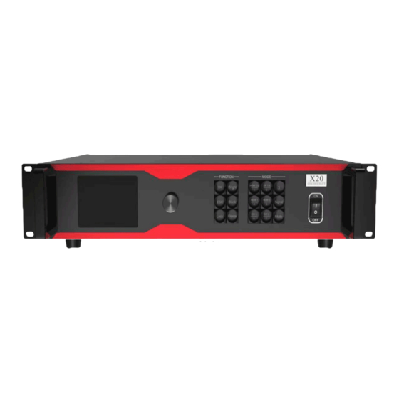
Page 5: Appearance
3 Appearance Front Panel Back Panel... - Page 6 Control Connector RJ11(6P6C)*, used to communicate via 3 party RS232 interfaces USB OUT USB output, for cascading with the X20 controller USB IN USB input, connecting to PC for debugging Audio Connector AUDIO IN Audio input AUDIO OUT...
-
Page 7: Application Scenarios
4 Application Scenarios 4.1 Ethernet Output... -
Page 8: Optical Fiber Output
4.2 Optical Fiber Output... -
Page 9: Software Operation Instruction
5 Software Operation Instruction Please make sure the hardware is properly connected before setting parameters, and that all senders and receiver cards can be detected by the software. You can visit www.colorlightinside.com to download LEDVISION installer. 5.1 Detect the Sender and Receiver Card Open LEDVISION, click Control, select LED Screen Settings from the drop-down list, and enter the password “168”. -
Page 10: Receiver Mapping Settings
Click Detect Receivers. On the Detect Receivers subpage, click Detect All Receivers, and the software will automatically acquire information such as the port, index, version, running time, and supported chips of the receiver card. Please check the corresponding cable if the number of receiver cards are inconsistent with actual status. 5.2 Receiver Mapping Settings Click Receiver Mapping to enter the receiver mapping setting page. -
Page 11: Mapping Settings
5.2.1 Mapping Settings Select the target Ethernet port on the left side, and then select the corresponding cabinets within the actual control area of the port and set the connection lines in the simulated cabinet area. In the simulated cabinet area, select the corresponding cabinet of the first receiver card based on the actual connection of the Ethernet port (view from the front), and left-click the cabinet one by one according to actual connecting line, until the last one this Ethernet port controls. -
Page 12: Backup Port Settings
5.2.3 Backup Port Settings Right-click the sequence number of the backup port, and select the target port that needs a backup. After setting, a backup sign will be displayed besides the sequence number of the backup port. 5.2.4 Reading Mapping Click Read in the lower-left corner of the page, and the mapping parameters of cabinets saved in the receiver cards can be read back. -
Page 13: Video Source Settings
5.3 Video Source Settings 5.3.1 Multi-window Display The device supports up to 6-window display. You can click to add a window, and then select the added window and switch signals in the Signal Selection area; or click to delete the selected window. -
Page 14: Window Settings
5.3.2 Window Settings In the lower-left corner of the Video Source Settings subpage, you can set the position and size of the selected window. You can also scale up or scale down the window by dragging the frame of the selected window. -
Page 15: Picture Adjustment
5.3.3 Picture Adjustment Click , and select the Enable check box, and then you can adjust the hue, saturation, brightness compensation and contrast values of the image. -
Page 16: Preset
5.3.4 Preset You can save 16 preset modes, and every preset mode includes the following parameter information of the video source setting: scaling, cropping, multi-window display, picture adjustment, color space, brightness and color temperature. You can also directly load the saved preset mode to display the image according to your need without needing to set up all the parameters again. -
Page 17: Genlock
Click Recall from Preset, select a preset item, and the screen will display image on the basis of the preset parameter. 5.3.5 Genlock The synchronous signal source can be any channel of input signals or Internal-Vsync. If the specified synchronous signal source has no signal, the main image will serve as the source. -
Page 18: Cropping
5.3.6 Cropping At the right side of the Video Source Settings subpage, click to enter the cropping setting window. In the cropping setting window, select the Enable check box, and set the row starting point (X), the column starting point (Y), and the width and height in the Cropping Settings area. -
Page 19: Edid (Resolution)
5.3.7 EDID (Resolution) In the lower-right corner of the Video Source Settings subpage, click In the Resolution (EDID) Setting dialog box, the resolution of the current sender is displayed by default. Click the dropdown button. From the resolution list, you can select a conventional resolution, or select Custom and set the width, height, frame rate and standard of the customized resolution. -
Page 20: Precise Color Management
5.4 Precise Color Management Select the Enable Precise Color Management check box in the upper-left corner of the Precise Color Management subpage, and you can modify the parameters of LED color and brightness, and color space. -
Page 21: Other
5.5 Other On the Other subpage, you can set Better Gray On Low Brightness, Mapping from Sender, Output Way (Ethernet port/ optical port) and Input Audio, adjust volume, modify the sender name, and select a test mode. -
Page 22: Lcd Operation Instruction
6 LCD Operation Instruction 6.1 Operation Instruction Knob/OK: In the main interface, press the knob/OK to enter the operation menu. ⚫ On the operation menu, rotate the knob to scroll to a menu item, press the knob/OK to ⚫ select the current item or enter the submenu. Rotate the knob to adjust parameters after selecting the menu item with the parameter ⚫... -
Page 23: Main Interface
6.2 Main Interface After starting up the X20 controller, the main interface of the LCD display is as follows: First row: Company logo Second row: Signal sources, Brightness Third and fourth row: Connection status of signal sources, Window layout Fifth row: Connection status of optical ports and Ethernet ports Sixth row: Sender name, Temperature 6.3 Menu Operation... -
Page 24: Display Setting
6.3.1 Display Setting Select Display Setting to enter the Display Setting submenu. Broadcast Press the knob/OK to turn on or off the Broadcast function. If the broadcast function is turned on, the setting of the menu items in this submenu (Brightness, Color Temperature, Better Gray, Picture Adjustment, Test Mode and Precise Color Management) will be synchronously sent to the devices cascaded with this controller. - Page 25 Picture Adjustment In the Picture Adjustment submenu, press the knob/OK to turn on or off Enable. If Enable is turned on, you can select Hue, Saturation, Brightness Compensation or Contrast and rotate the knob to modify their values, or select Reset to reset the hue value as 0, saturation value as 100, brightness value as 0, and contrast value as 100.
-
Page 26: Edid Setting
Precise Color Management In the Precise Color Management menu, you can press the knob/OK to turn on or off Precise Color Management. If Precise Color Management is turned on, you can select Color & Bright, and set Color and Bright as Unknow, Measured Value or Quick Input (you can set color space and luminance when Color and Bright is set as Quick Input). -
Page 27: Cropping Setting
In the EDID setting submenu of signals (take HDMI (2.0) as an example), you can rotate the knob and select a conventional resolution to save the selected resolution to the sender, or select Custom and rotate the knob to adjust the width, height and frame rate of resolution, and then select Save to save the setting in the sender. -
Page 28: Window
6.3.4 Window Rotate the knob and select Window to enter the Window submenu, in which you can set the canvas size, window number and the signal, row starting point, column starting point, width and height of the window. 6.3.5 Output Setting Rotate the knob and select Output Setting to enter the Output Setting submenu, in which you can choose an output way (By Network, By Fiber). -
Page 29: Preset Setting
6.3.7 Preset Setting Rotate the knob and select Preset Setting to enter the Preset Setting submenu. In the submenu, you can press the knob/OK to turn on or off the broadcast function. If Include Color and Bright Related is checked, and you select Save to Preset, then you can save the parameters of the current image that include color and brightness information. -
Page 30: Tiles Mapping
6.3.9 Tiles Mapping Select Tiles Mapping to enter the Tiles Mapping submenu. In the submenu, press the knob/OK to turn on or off From Sender. If From Sender is turned on, the sender is set as the connection source. Then select Set by Port to enter the submenu, in which you can choose the Ethernet port from 1 to 20 that needs setting mapping, and set the row offset value(X) and column offset value(Y) of the port, and the width, height, row number, column number and link type of the corresponding cabinets. -
Page 31: Language Setting
Output shift includes two selections: Whole and By Port. On the submenu of Whole, you can rotate the knob to set the row starting point (X) and column starting point (Y) of the whole image and save the setting; on the submenu of By Port, you can respectively set the row starting point (X) and column starting point (Y) of the image of the 20 Ethernet ports and save the setting.
Need help?
Do you have a question about the X20 and is the answer not in the manual?
Questions and answers