Table of Contents
Advertisement
Quick Links
Advertisement
Table of Contents

Related Manuals for Colorlight X16


Summary of Contents for Colorlight X16
- Page 1 X16 Controller...
-
Page 2: Table Of Contents
Content 1. Safety Information .............................. 1 2. Overview ................................2 3. Appearance ................................. 3 4. Software Operation Instruction ......................... 5 4.1 Detect the Sender and Receiving Card ....................5 4.2 Receiver Mapping Settings ........................6 4.2.1 Mapping Settings .......................... 7 4.2.2 Saving Mapping .......................... -
Page 3: Safety Information
www.colorlightinside.com 1. Safety Information To prevent personal injury and to protect the device from damage, read and follow these safety precautions. ⚫ Do not remove the cover To avoid personal injury, do not remove the top cover. ⚫ Only use the power supply and accessories specified by the manufacturer The operating voltage of this product is 100V-240V AC. -
Page 4: Overview
(HDMI, DVI, SDI), and seamless switching between signals. It also supports splicing, broadcast quality scaling, and 7-window display. The X16 adopts 16 Gigabit Ethernet outputs. Meanwhile, the X16 is equipped with a series of versatile functions which can provide flexible screen control and high-quality image displays. -
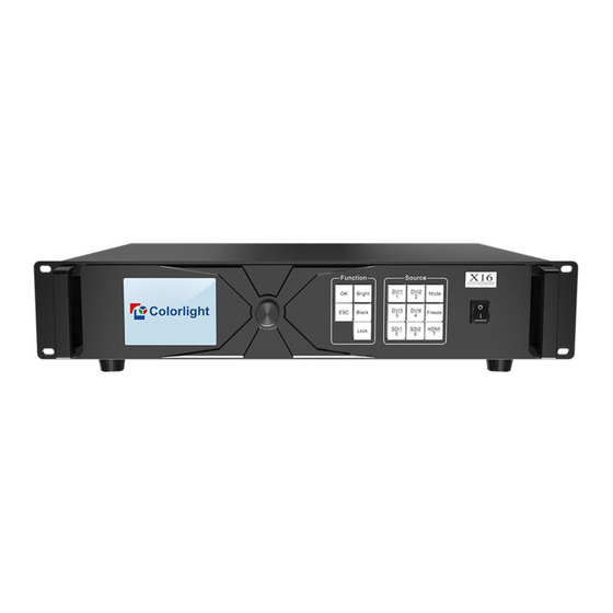
Page 5: Appearance
www.colorlightinside.com 3. Appearance The Front Panel The Back Panel... - Page 6 www.colorlightinside.com Input Interface 2×3G-SDI 1×HDMI 2.0 HDMI 4×DVI Output Interface Port1-16 RJ45,16 Gigabit Ethernet outputs, which can be arbitrarily spliced Controlling Interface Network control (communication with PC, or access network) USB IN USB input, connecting to PC for debugging USB OUT USB output, for cascading with the next controller Genlock signal input, ensuring synchronism of display image Genlock...
-
Page 7: Software Operation Instruction
www.colorlightinside.com 4. Software Operation Instruction Please make sure the hardware is properly connected before setting parameters, and that all senders and receiver cards can be detected by the software. You can visit www.colorlightinside.com to download LEDVISION installation package. 4.1 Detect the Sender and Receiving Card Open LEDVISION, click Control, select LED Screen Settings from the drop-down list, and enter the password “168”. -
Page 8: Receiver Mapping Settings
www.colorlightinside.com Click Detect Receivers. On the Detect Receivers sub-page, click Detect All Receivers, and the software will automatically acquire information such as the port, index, running time, and supported chips of the receiver card. Please check the corresponding cable if the number of receiver cards are inconsistent with actual status. 4.2 Receiver Mapping Settings Click Receiver Mapping to enter the receiver mapping setting page. -
Page 9: Mapping Settings
www.colorlightinside.com 4.2.1 Mapping Settings Select the target Ethernet port on the left side, and then select the corresponding cabinets within the actual control area of the port and set the connection lines in the simulated cabinet area. In the simulated cabinet area, select the corresponding cabinet of the first receiving card based on the actual connection of the Ethernet port (view from the front), and left-click the cabinet one by one according to actual connecting line, until the last one this Ethernet port controls. -
Page 10: Port Backup Setting
www.colorlightinside.com 4.2.3 Port Backup Setting Right-click the sequence number of the backup port, and select the target port that needs a backup. After setting, a backup sign will be displayed besides the sequence number of the backup port. 4.2.4 Read Mapping Click Read in the lower-left corner of the page, and the mapping parameters of cabinets saved in the receiving cards can be read back. -
Page 11: Video Source Settings
www.colorlightinside.com 4.3 Video Source Settings 4.3.1 Multi-window Display The device supports up to 7-window display. You can add or delete windows based on your own need, and set each window. Click to add a window, select the added window and then select other signals as input source, namely adding other windows. -
Page 12: Window Settings
www.colorlightinside.com 4.3.2 Window Settings In the lower-left corner of the Video Source Settings sub-page, you can set the position and size of the selected window. You can also scale up or scale down the window by dragging the frame of the selected window. -
Page 13: Picture Adjustment
www.colorlightinside.com 4.3.3 Picture Adjustment Click and select the Enable check box, and then you can adjust the hue, saturation, brightness compensation and contrast values of the image. -
Page 14: Preset
www.colorlightinside.com 4.3.4 Preset You can save 16 presets, and every preset includes the following parameter information: scaling, cropping, multi-window display, picture adjustment and 3D. You can also directly load the saved preset parameters to display the image according to your need without needing to set up all the parameters again. -
Page 15: Genlock
www.colorlightinside.com Click Recall from Preset, select a preset item, and the screen will display image on the basis of the preset parameter. 4.3.5 Genlock Synchronous signal source supports Genlock and every channel of input signals. When there is no specified synchronous signal source or the specified synchronous signal source has no signal, the main image is regarded as synchronous signal source. -
Page 16: Cropping
www.colorlightinside.com 4.3.6 Cropping In the lower-right corner of the Video Source Settings sub-page, click to enter the cropping setting window. In the cropping setting window, select the Cropping check box, and set the row starting point (X), the column starting point (Y), and the width and height in the Cropping Settings area. -
Page 17: Edid (Resolution)
www.colorlightinside.com 4.3.7 EDID (Resolution) In the lower-right corner of the Video Source Settings sub-page, click In the Resolution (EDID) Setting dialog box, the resolution of the current sender is displayed by default. Click the dropdown button. From the resolution list, you can select a conventional resolution, or select Custom and set the width, height, frame rate and standard of the customized resolution. -
Page 18: Network
www.colorlightinside.com After setting, click Save. 4.4 Network Click Network. On the Network sub-page, click Obtain an IP Address Automatically, and the device will automatically obtain the IP address. Or you can click Use the Following IP Address, and then manually enter the IP address, subnet mask and default gateway. After setting, click Save. - Page 19 4.5 3D X16 controller supports 3D display on ordinary LED screens. After detecting the X16 controller, click 3D to enter the 3D sub-page, on which you can set 3D. On the page, select the Enable 3D check box, and select the same signal from the Left Eye and Right Eye list, and then set Parameter Adjustment to achieve good display effect.
-
Page 20: Other
www.colorlightinside.com 4.6 Other On the Other sub-page, you can select or clear the Better Graylevel on Low Brightness, Mapping from Sender and Turbo Mode (50Hz maximum) check box, modify the device name, and switch the test mode based on your specific need. -
Page 21: Lcd Operation Instruction
www.colorlightinside.com 5. LCD Operation Instruction 5.1 Operation Instruction Knob/OK: ⚫ In the main interface, press the knob/OK to enter the operation menu; ⚫ On the operation menu, rotate the knob to scroll to a menu item, press the knob/OK to select the current item or enter the submenu;... -
Page 22: Main Interface
5.2 Main Interface After starting up the X16 controller, the main interface of the LCD display is as follows: First row: Company logo Second row: Signal source, Brightness Third and fourth row: Connection status of signal source and Genlock... - Page 23 www.colorlightinside.com Broadcast Press the knob/OK to turn on or off the Broadcast function. If the broadcast function is turned on, the setting of the menu items in this submenu (Brightness, Color Temperature, Black, Better Gray, Test Mode, Test Mode(50Hz), 3D) will be synchronously sent to the devices cascaded with this controller.
- Page 24 www.colorlightinside.com Better Gray Press the knob/OK to turn on or off the Better Gray function. Test Mode In the Test Mode menu, you can select a test mode. Test Mode (50Hz) Press the knob/OK to turn on or off Test Mode (50Hz). If Test Mode (50Hz) is turned on, the frame rate of input signals will change from 60Hz to 50 Hz, and the loading capacity will change from 8.88 million to 10.88 million.
-
Page 25: Edid Setting
www.colorlightinside.com 5.3.2 EDID Setting Rotate the knob and select EDID Setting to enter the EDID Setting submenu that displays different options of signals corresponding to the combination of daughter boards. (Take HDMI daughter board and DVI daughter board as an example). In the EDID setting submenu of HDMI and DVI1/2/3/4 (take HDMI as an example), you can rotate the knob and select a conventional resolution to save the selected resolution to the sender, or select Custom and rotate the knob to adjust the width, height and frame rate,... -
Page 26: Preset Setting
www.colorlightinside.com In the cropping setting submenu of HDMI or DVI1/2/3/4 or SDI1/2, press the knob/OK to turn the cropping function on or off. If Enable has been switched on, you can rotate the knob to set the row starting point (X), the column starting point (Y), and the width and height of the signal image, and then select Save. -
Page 27: Output Setting
www.colorlightinside.com 5.3.5 Output Setting Rotate the knob and select Output Setting to enter the Output Setting submenu. Select Number Of Pictures and rotate the knob to set the number of pictures from 1 to 7; Select Main or PIP to enter its output setting submenu, and rotate the knob to set the input signal of the output picture and adjust the row starting point (X), the column starting point (Y), and the width and height of the output picture. -
Page 28: Lock To Input
www.colorlightinside.com 5.3.7 Lock to Input When several controllers are cascaded with each other, Lock to Input is necessary to ensure the synchronization of the video displays. Rotate the knob and select Lock to Input to enter the submenu. On the submenu, you can select a sync signal source. 5.3.8 Tile Mapping Rotate the knob and select Tile Mapping to enter the Tile Mapping submenu. -
Page 29: Network Setting
www.colorlightinside.com corresponding cabinets. Finally select Save to save the mapping. 5.3.9 Network Setting You can choose automatically obtaining IP address or manually setting static IP address. Enter the Network Setting submenu, and press the knob/OK to turn the DHCP function on or off, or select IP Setting to enter the submenu, in which you can set the IP address, subnet and gateway via the knob. -
Page 30: System Setting
www.colorlightinside.com 5.3.11 System Setting In the System Setting menu, you can restore factory settings and view the current version and its details.
Need help?
Do you have a question about the X16 and is the answer not in the manual?
Questions and answers