Table of Contents
Advertisement
Quick Links
PHLEBOTOMY COLLECTION
OWNERS OPERATING AND MAINTENANCE MANUAL
Solace BDC
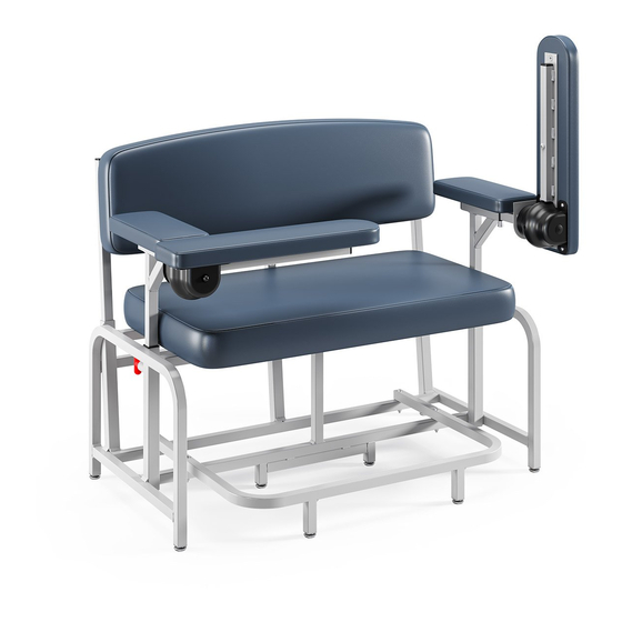
Spirit BDC
(2572 / 2573)
(2570 / 2571)
Shown: 2570
Shown: 2572
Unity BDC
(2574 / 2575)
Shown: 2574
Elevate BDC
Harmony BDC
(2578)
(2580)
Shown: 2580-DL-FR
Shown: 2578
IMPORTANT! DO NOT DISCARD THIS MANUAL!
KEEP THIS MANUAL FOR FUTURE REFERENCE AND TRAINING!
Advertisement
Table of Contents

Related Manuals for Winco Spirit BDC Series


Summary of Contents for Winco Spirit BDC Series
- Page 1 PHLEBOTOMY COLLECTION OWNERS OPERATING AND MAINTENANCE MANUAL Solace BDC Spirit BDC (2572 / 2573) (2570 / 2571) Shown: 2570 Shown: 2572 Unity BDC (2574 / 2575) Shown: 2574 Elevate BDC Harmony BDC (2578) (2580) Shown: 2580-DL-FR Shown: 2578 IMPORTANT! DO NOT DISCARD THIS MANUAL! KEEP THIS MANUAL FOR FUTURE REFERENCE AND TRAINING!
- Page 3 IF YOU HAVE ANY QUESTIONS OR CONCERNS, PLEASE CONTACT WINCO MFG., LLC. Winco assumes no responsibility for damage or injury caused by improper assembly, installation, use, or maintenance of these products. No part of this manual may be duplicated in any form without the prior consent of Winco Mfg., LLC.
-
Page 4: Table Of Contents
OWNERS OPERATING & MAINTENANCE MANUAL PHLEBOTOMY COLLECTION TABLE OF CONTENTS IMPORTANT SAFETY INFORMATION ..............................6 INTENDED USE STATEMENT ................................. 6 TRANSPORTATION, STORAGE, HANDLING & DISPOSAL INSTRUCTIONS ................6 GENERAL CARE & CLEANING ................................7 TOOLS REQUIRED ....................................8 GLIDE FOOT INSTALLATION ........................................9 SEAT INSTALLATION .......................................... - Page 5 OWNERS OPERATING & MAINTENANCE MANUAL PHLEBOTOMY COLLECTION HARMONY BDC: MODEL 2580 ................................35 GLIDE FOOT INSTALLATION ........................................35 SEAT INSTALLATION ..........................................35 BACK INSTALLATION AND ADJUSTMENT .................................... 36 SHORT ARM INSTALLATION ........................................36 ARM HEIGHT ADJUSTMENTS ........................................36 L-ARM INSTALLATION ..........................................37 L-ARM LEVEL ADJUSTMENTS .........................................
-
Page 6: Important Safety Information
7. STAY CLEAR of moving parts 8. DO NOT use chair for transporting in or with ANY type of vehicle or trailer. Winco chairs have not been tested or approved for use by an occupant in any type of vehicle or trailer 9. -
Page 7: General Care & Cleaning
GENERAL CARE & CLEANING • Periodically inspect tightness of all screws, bolts, nuts, or other fasteners. Winco Mfg., LLC’s full-line of products are built to provide durability and reliability when properly cared for. In general all of our products should be: Cleaned 2. -
Page 8: Tools Required
IF YOU HAVE ANY QUESTIONS OR CONCERNS, PLEASE CONTACT WINCO MFG., LLC. WINCO ASSUMES NO RESPONSIBILITY FOR DAMAGE OR INJURY CAUSED BY IMPROPER ASSEMBLY, INSTALLATION, USE, OR MAINTENANCE OF THESE PRODUCTS. Page 8 of 49 Document No.: 006020... -
Page 9: Glide Foot Installation
OWNERS OPERATING & MAINTENANCE MANUAL PHLEBOTOMY COLLECTION SPIRIT BDC: MODEL 2570/2571 SHOWN: Model 2570 Spirit BDC with Cabinet SHOWN: Model 2571 Spirit BDC with Standard Arm GLIDE FOOT INSTALLATION Place chair on side and install four (4) Glide Feet in threaded holes on the bottom of the Chair Frame (FIG. -
Page 10: Seat Installation
OWNERS OPERATING & MAINTENANCE MANUAL PHLEBOTOMY COLLECTION SEAT INSTALLATION FAILURE TO COMPLETELY TIGHTEN THE SEAT MOUNTING SCREWS COULD RESULT IN SERIOUS INJURY. Position Chair Frame in upright position. Check tightness of all installed screws, bolts, nuts and other fasteners in case they loosened during shipping. 2. -
Page 11: Arm Assembly And Installation
OWNERS OPERATING & MAINTENANCE MANUAL PHLEBOTOMY COLLECTION ARM ASSEMBLY AND INSTALLATION If the Arm Assembly has not yet been installed, insert it into the Receiving Tube on the Seat Frame Assembly. (FIG. 1) *This applies to any style arm assembly) ALWAYS make sure that the slot in the Arm Assembly faces the Knob installed on the receiving tube. -
Page 12: Urethane Flip-Up Arm Adjustments
OWNERS OPERATING & MAINTENANCE MANUAL PHLEBOTOMY COLLECTION URETHANE FLIP-UP ARM LEVEL ADJUSTMENTS Use a ⅛” Hex Key to make minor leveling adjustments to the Urethane Flip-Up Armrest as needed. Rest the Hinge Plate flat on the Hinge Arm Support Bracket. 2. -
Page 13: Cabinet Assembly And Installation
OWNERS OPERATING & MAINTENANCE MANUAL PHLEBOTOMY COLLECTION CABINET ASSEMBLY AND INSTALLATION * MODEL 2570 Remove the cabinet from the frame (FIG 1)Use CAUTION to avoid personal injury or damaging the product. Fig 1 2. Remove packaging materials from cabinet assembly. 3. -
Page 14: Removing And Re-Installing Cabinet Drawer
OWNERS OPERATING & MAINTENANCE MANUAL PHLEBOTOMY COLLECTION REMOVING AND RE-INSTALLING CABINET DRAWER * MODEL 2570 To remove drawer, open drawer until the drawer stops. Using your finger, locate the drawer stop tab mounted to the bottom of the drawer top. Press the tab against the drawer top and slide the drawer past the tab. -
Page 15: Pivot Arm Pivot-Point Adjustment
OWNERS OPERATING & MAINTENANCE MANUAL PHLEBOTOMY COLLECTION PIVOT ARM PIVOT-POINT ADJUSTMENT Your Pivot Arm Assembly may be configured in one of two (2) directions: • Pivot point located near the back of the chair. This will provide arm support that is straight or at a slight angle to the side of the patient (standard position). -
Page 16: Solace Bdc: Model 2572/2573
OWNERS OPERATING & MAINTENANCE MANUAL PHLEBOTOMY COLLECTION SOLACE BDC: MODEL 2572/2573 SHOWN: Model 2572 Solace BDC with Cabinet SHOWN: Model 2573 Solace BDC with Standard Arm GLIDE FOOT INSTALLATION Place chair on side and install four (4) Glide Feet in threaded holes on the bottom of the Chair Frame (FIG. -
Page 17: Seat Installation
OWNERS OPERATING & MAINTENANCE MANUAL PHLEBOTOMY COLLECTION SEAT INSTALLATION FAILURE TO COMPLETELY TIGHTEN THE SEAT MOUNTING SCREWS COULD RESULT IN SERIOUS INJURY. Position Chair Frame in upright position. Check tightness of all installed screws, bolts, nuts and other fasteners in case they loosened during shipping. 2. -
Page 18: Arm Assembly And Installation
OWNERS OPERATING & MAINTENANCE MANUAL PHLEBOTOMY COLLECTION ARM ASSEMBLY AND INSTALLATION If the Arm Assembly has not yet been installed, insert it into the Receiving Tube on the Seat Frame Assembly. (FIG. 1) *This applies to any style arm assembly. ALWAYS make sure that the slot in the Arm Assembly faces the Knob installed on the receiving tube. -
Page 19: Urethane Flip-Up Arm Adjustments
OWNERS OPERATING & MAINTENANCE MANUAL PHLEBOTOMY COLLECTION URETHANE FLIP-UP ARM LEVEL ADJUSTMENTS Use a ⅛” Hex Key to make minor leveling adjustments to the Urethane Flip-Up Armrest as needed. Rest the Hinge Plate flat on the Hinge Arm Support Bracket. 2. -
Page 20: Cabinet Assembly And Installation
OWNERS OPERATING & MAINTENANCE MANUAL PHLEBOTOMY COLLECTION CABINET ASSEMBLY AND INSTALLATION * MODEL 2572 Remove the cabinet from the frame (FIG 1)Use CAUTION to avoid personal injury or damaging the product. Fig 1 2. Remove packaging materials from cabinet assembly. 3. -
Page 21: Removing And Re-Installing Cabinet Drawer
OWNERS OPERATING & MAINTENANCE MANUAL PHLEBOTOMY COLLECTION REMOVING AND RE-INSTALLING CABINET DRAWER * MODEL 2572 To remove drawer, open drawer until the drawer stops. Using your finger, locate the drawer stop tab mounted to the bottom of the drawer top. Press the tab against the drawer top and slide the drawer past the tab. -
Page 22: Pivot Arm Pivot-Point Adjustment
OWNERS OPERATING & MAINTENANCE MANUAL PHLEBOTOMY COLLECTION PIVOT ARM PIVOT-POINT ADJUSTMENT Your Pivot Arm Assembly may be configured in one of two (2) directions: • Pivot point located near the back of the chair. This will provide arm support that is straight or at a slight angle to the side of the patient (standard position). -
Page 23: Unity Bdc: Model 2574/2575
OWNERS OPERATING & MAINTENANCE MANUAL PHLEBOTOMY COLLECTION UNITY BDC: MODEL 2574/2575 SHOWN: Model 2574 Unity BDC with Cabinet SHOWN: Model 2575 Unity BDC with Standard Arm GLIDE FOOT INSTALLATION Place chair on side and install four (4) Glide Feet in threaded holes on the bottom of the Chair Frame (FIG. -
Page 24: Seat Installation
OWNERS OPERATING & MAINTENANCE MANUAL PHLEBOTOMY COLLECTION SEAT INSTALLATION FAILURE TO COMPLETELY TIGHTEN THE SEAT MOUNTING SCREWS COULD RESULT IN SERIOUS INJURY. Position Chair Frame in upright position. Check tightness of all installed screws, bolts and nuts in case they loosened during shipping. 2. -
Page 25: Arm Assembly And Installation
OWNERS OPERATING & MAINTENANCE MANUAL PHLEBOTOMY COLLECTION ARM ASSEMBLY AND INSTALLATION If the Arm Assembly has not yet been installed, insert it into the Receiving Tube on the Seat Frame Assembly. (FIG. 1) *This applies to any style arm assembly. ALWAYS make sure that the slot in the Arm Assembly faces the Knob installed on the receiving tube. -
Page 26: Urethane Flip-Up Arm Adjustments
OWNERS OPERATING & MAINTENANCE MANUAL PHLEBOTOMY COLLECTION URETHANE FLIP-UP ARM LEVEL ADJUSTMENTS Use a ⅛” Hex Key to make minor leveling adjustments to the Urethane Flip-Up Armrest as needed. Rest the Hinge Plate flat on the Hinge Arm Support Bracket. 2. -
Page 27: Cabinet Assembly And Installation
OWNERS OPERATING & MAINTENANCE MANUAL PHLEBOTOMY COLLECTION CABINET ASSEMBLY AND INSTALLATION * MODEL 2574 Remove the cabinet from the frame (FIG 1)Use CAUTION to avoid personal injury or damaging the product. Fig 1 2. Remove packaging materials from cabinet assembly. 3. -
Page 28: Removing And Re-Installing Cabinet Drawer
OWNERS OPERATING & MAINTENANCE MANUAL PHLEBOTOMY COLLECTION REMOVING AND RE-INSTALLING CABINET DRAWER * MODEL 2574 To remove drawer, open drawer until the drawer stops. Using your finger, locate the drawer stop tab mounted to the bottom of the drawer top. Press the tab against the drawer top and slide the drawer past the tab. -
Page 29: Pivot Arm Pivot-Point Adjustment
OWNERS OPERATING & MAINTENANCE MANUAL PHLEBOTOMY COLLECTION PIVOT ARM PIVOT-POINT ADJUSTMENT Your Pivot Arm Assembly may be configured in one of two (2) directions: • Pivot point located near the back of the chair. This will provide arm support that is straight or at a slight angle to the side of the patient (standard position). -
Page 30: Elevate Bdc: Model 2578
OWNERS OPERATING & MAINTENANCE MANUAL PHLEBOTOMY COLLECTION ELEVATE BDC: MODEL 2578 SHOWN: Model 2578 Elevate BDC GLIDE FOOT INSTALLATION Place chair on side and install four (4) Glide Feet in threaded holes on the bottom of the Chair Frame (FIG. 6A & 7A). Fig 6a Fig 7a 2. -
Page 31: Seat Installation
OWNERS OPERATING & MAINTENANCE MANUAL PHLEBOTOMY COLLECTION SEAT INSTALLATION FAILURE TO COMPLETELY TIGHTEN THE SEAT MOUNTING SCREWS COULD RESULT IN SERIOUS INJURY. Position Chair Frame in upright position. Check tightness of all installed screws, bolts, nuts and other fasteners in case they loosened during shipping. 2. -
Page 32: Seat Height Set-Up And Adjustment
OWNERS OPERATING & MAINTENANCE MANUAL PHLEBOTOMY COLLECTION SEAT HEIGHT SET-UP AND ADJUSTMENT The seat height of the 2578 Elevate BDC can be adjusted during setup. THE SEAT ASSEMBLY IS VERY HEAVY - TO ADJUST THE HEIGHT, THE CHAIR MUST BE SUPPORTED BY SOMEONE WHO CAN LIFT OVER 50 LBS. *TEAM LIFT RECOMMENDED* Use TWO (2) people! Use the included 3/16”... -
Page 33: Arm Assembly And Installation
OWNERS OPERATING & MAINTENANCE MANUAL PHLEBOTOMY COLLECTION ARM ASSEMBLY AND INSTALLATION If the Arm Assembly has not yet been installed, insert it into the Receiving Tube on the Seat Frame. (FIG. 1) *This applies to any style arm assembly ALWAYS make sure that the slot in the Arm Assembly faces the Knob installed on the receiving tube. -
Page 34: Pivot Arm Pivot-Point Adjustment
OWNERS OPERATING & MAINTENANCE MANUAL PHLEBOTOMY COLLECTION PIVOT ARM PIVOT-POINT ADJUSTMENT If you wish to change the standard setup of the Pivot Arm so that the pivot point is toward the front of the chair, proceed to the next step. Otherwise, skip this section. If you ordered a P2 Option, you can choose which Pivot Arm(s), if any, you wish to alter. -
Page 35: Harmony Bdc: Model 2580
OWNERS OPERATING & MAINTENANCE MANUAL PHLEBOTOMY COLLECTION HARMONY BDC: MODEL 2580 SHOWN: Model 2580-dl Harmony BDC with Dual L-Arms SHOWN: Model 2580-dl-fr Harmony BDC with Dual L-Arms and Optional Footrest GLIDE FOOT INSTALLATION Place chair on side and install four (4) Glide Feet in threaded holes on the bottom of the Chair Frame (FIG. -
Page 36: Back Installation And Adjustment
OWNERS OPERATING & MAINTENANCE MANUAL PHLEBOTOMY COLLECTION BACK INSTALLATION AND ADJUSTMENT All configurations of model 2580 arrive with the back attached and in the lowest position. No back installation is required however, the back must be adjusted before use. Remove all packaging being careful not to cut too deep. Upholstered items enclosed!. 2. -
Page 37: L-Arm Installation
OWNERS OPERATING & MAINTENANCE MANUAL PHLEBOTOMY COLLECTION L-ARM INSTALLATION Pull down on spring loaded pin 2. Align L-Arm Assembly (holes facing floor) to Short Arm Assembly and slide into tube 3. Release spring loaded pin and adjust until pin engages on one of the five adjustment holes ... -
Page 38: Changing The Position Of L-Arm
OWNERS OPERATING & MAINTENANCE MANUAL PHLEBOTOMY COLLECTION L-ARM LEVEL ADJUSTMENTS - CONTINUED 2. Using the provided #2 screwdriver bit is in place (FIG C) 3. Place bit into hole in safety cover (aligned with tube) engaging leveling screw (FIG B). There are 3 holes, use the hole nearest patient surface. FIG B FIG C ARM SHOWN ON PATIENT LEFT... -
Page 39: Changing The Position Of L-Arm
OWNERS OPERATING & MAINTENANCE MANUAL PHLEBOTOMY COLLECTION CHANGING THE POSITION OF L-ARM 2. Using #2 screwdriver provided (FIG 3), remove 4 Screws (FIG 2) FIG 2 FIG 3 3. Remove O-Ring & Flat Safety Cover (FIG 4-B & C) by sliding off of L-Arm Tube (FIG 4-D) FIG 4 Page 39 of 49 Document No.: 006020... - Page 40 OWNERS OPERATING & MAINTENANCE MANUAL PHLEBOTOMY COLLECTION CHANGING THE POSITION OF L-ARM - CONTINUED 4. Rotate Arm Tube (FIG 5-D) until it stops 5. Lift & Tip the end of the Safety Cover (FIG 5-E): Lift end with large opening up first, then slide cover back to clear bolt cap (FIG 5-F) –...
- Page 41 OWNERS OPERATING & MAINTENANCE MANUAL PHLEBOTOMY COLLECTION CHANGING THE POSITION OF L-ARM - CONTINUED 7. Remove/pull out Arm Tube (FIG 8-J) and re-install in opposite end following picture on label (FIG 8-K) lining up A-A or B-B based on Patient LH or RH 8.
-
Page 42: Side Cabinet Assembly
OWNERS OPERATING & MAINTENANCE MANUAL PHLEBOTOMY COLLECTION SIDE CABINET ASSEMBLY 2580 models ordered with a cabinet (2580-CL and 2580-CS) will arrive with a pre-assembled cabinet configured for installation on the Patient Left Side of the main frame. SIDE CABINET INSTALLATION INSTALLATION ON PATIENT LEFT: Remove the pre-assembled side cabinet module from the box. - Page 43 OWNERS OPERATING & MAINTENANCE MANUAL PHLEBOTOMY COLLECTION SIDE CABINET INSTALLATION - CONTINUED INSTALLATION ON PATIENT RIGHT: Remove Cabinet Assembly & lay on a flat 2. Remove two (2) 5/16-18 bolts using wrench non-marring surface (FIG 1) provided (FIG 2) Fig 1 Fig 2 NOTE: DRAWER OPENING TO LEFT 3.
-
Page 44: Removing And Re-Installing Cabinet Drawer
OWNERS OPERATING & MAINTENANCE MANUAL PHLEBOTOMY COLLECTION REMOVING AND RE-INSTALLING CABINET DRAWER * MODELS 2580-CL AND 2580-CS To remove drawer, open drawer until the drawer stops. Using your finger, locate the drawer stop tab mounted to the bottom of the drawer top. Press the tab against the drawer top and slide the drawer past the tab. -
Page 45: Optional Footrest Installation
OWNERS OPERATING & MAINTENANCE MANUAL PHLEBOTOMY COLLECTION OPTIONAL FOOTREST INSTALLATION *2580 MODELS WITH THE "FR" OPTION Remove four (4) clip plugs and four (4) clip bases Clip Plug Clip Base 2. Install Glide Feet in threaded holes on bottom of the Footrest frame (See Page 35) 3. -
Page 46: Specifications
OWNERS OPERATING & MAINTENANCE MANUAL PHLEBOTOMY COLLECTION ALWAYS REFER TO THE WEIGHT CAPACITY LABEL ON YOUR CHAIR. IN ALL CASES THE LABELING ON THE CHAIR AT THE TIME OF DELIVERY INDICATES THE CORRECT RATING FOR YOUR CHAIR - WEIGHT RATING SHOULD NOT BE EXCEEDED! SPECIFICATIONS 2570 / 2571: Spirit BDC 2572 / 2573: Solace BDC... - Page 47 OWNERS OPERATING & MAINTENANCE MANUAL PHLEBOTOMY COLLECTION ALWAYS REFER TO THE WEIGHT CAPACITY LABEL ON YOUR CHAIR. IN ALL CASES THE LABELING ON THE CHAIR AT THE TIME OF DELIVERY INDICATES THE CORRECT RATING FOR YOUR CHAIR - WEIGHT RATING SHOULD NOT BE EXCEEDED! SPECIFICATIONS 2580 / 2580-SL / 2580-DL / 2580-CL / 2580-CS: Harmony BDC Refer to chair label for weight capacity...
-
Page 48: Warranty Information
Limited One Year Complete Product Warranty: Winco Mfg., LLC warrants the complete product for one (1) year. At Winco Mfg., LLC’s sole discretion, it may repair or replace any components that are found to be defective during the first year after shipment from the Winco facilities. Winco Mfg., LLC, shall not be liable for any labor, or any other costs incurred as a result of or in conjunction with a warranty claim. -
Page 49: Document No
We reserve the right to add or delete products at any time and without prior notice. Always provide your product's specific serial number when ordering any replacement parts. When in doubt, contact a Winco representative (352-854-2929 or 1-800-237-3377) for further information. - Page 52 Document No.: 006020 Owners Operating and Maintenance Manual Revision: P Copyright © 2019 Winco Mfg., LLC CONTACT US To arrange a demonstration or to speak with one of our associates, please feel free to contact us at: 800-237-3377 | WincoMfg.com | 5516 SW 1st Lane, Ocala, FL 34474 | Info@WincoMfg.com...
Need help?
Do you have a question about the Spirit BDC Series and is the answer not in the manual?
Questions and answers