Table of Contents
Advertisement
Manual
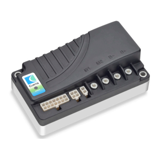
Model 1212S
Electronic Motor Controller
Read Instructions Carefully!
Specifications are subject to change without notice.
© 2016 Curtis Instruments, Inc. ® Curtis is a registered trademark of Curtis Instruments, Inc.
© The design and appearance of the products depicted herein are the copyright of Curtis Instruments, Inc.
Curtis Instruments, Inc.
200 Kisco Avenue
Mt. Kisco, NY 10549
www.curtisinstruments.com
53153 Rev B 10/2016
Advertisement
Table of Contents
Troubleshooting

Related Manuals for Curtis 1212S


Summary of Contents for Curtis 1212S
- Page 1 Specifications are subject to change without notice. © 2016 Curtis Instruments, Inc. ® Curtis is a registered trademark of Curtis Instruments, Inc. © The design and appearance of the products depicted herein are the copyright of Curtis Instruments, Inc. 53153 Rev B 10/2016...
-
Page 2: Table Of Contents
6. VEHICLE PERFORMANCE ADJUSTMENT ..... 27 7. DIAGNOSTICS AND TROUBLESHOOTING ....32 8. MAINTENANCE ..............35 appendix a Vehicle Design Considerations appendix b EN 13849 Compliance, 1212S Controller appendix c Battery Discharge Indicator (BDI) Setup appendix d Programming Devices appendix e 1212S Controller Specifications... - Page 3 FIGURES . 1: Curtis 1212S electronic motor controller ......... 1 . 2: Mounting dimensions, Curtis 1212S controller ....... 4 . 3: Standard wiring configuration, 1212S controller ...... 6 . 4: Wiring for 5kΩ, 3-wire potentiometer ........7 . 5: Wiring for voltage throttle ............7 .
-
Page 4: Overview
This controller is designed for use in pallet truck applications. The 1212S controller is fully programmable by means of a Curtis pro- gramming device. Use of the programmer offers diagnostic and test capability as well as configuration flexibility. - Page 5 ✓ Emergency stop provides immediate EM braking when throttle transitioned through neutral to >80% reverse request ✓ Lift Lockout input from Curtis 906 battery discharge indicator meter ✓ Output Lift Lockout signal, which can drive a pump contactor ✓ Pump SRO can be enabled to prevent pump startup when KSI first turned on...
- Page 6 ✓ On power-up, system automatically checks the throttle, brake, and associated wiring, and disables drive if a fault is found ✓ Whenever the 1212S senses a loss of KSI or any fault that requires a stop, it smoothly decelerates the vehicle to a stop Meets or Complies with Relevant US and International regulations ✓...
-
Page 7: Installation And Wiring
INSTALLATION AND WIRING MOUNTING THE CONTROLLER The 1212S controller can be oriented in any position, but the location should be carefully chosen to keep the controller clean and dry. If a clean, dry mounting location cannot be found, a cover must be used to shield the controller from water and contaminants. -
Page 8: Connections: High Current
J2 Pin 3 Tx/charge inhibit J2 Pin 4 +15V The mating connectors are: J1 Molex Mini-Fit-Jr. receptacle p/n 39-01-2140 J2 Molex Mini-Fit-Jr. receptacle p/n 39-01-2040 J3 Molex Mini-Fit-Jr. receptacle p/n 39-01-2020, all with appropriate 45750-series crimp terminals. Curtis 1212S Manual, Rev. B... -
Page 9: Controller Wiring
WIRING: STANDARD INSTALLATION, 1212S The wiring diagram presented in Figure 3 shows a typical installation for a pallet truck application. This installation is shown with a Curtis ET-1XX MCU electronic throttle. The J2 connector can be used interchangeably for the programmer or for the charge inhibit input. -
Page 10: Throttle Wiring
2 — INSTALLATION & WIRING: Throttle THROTTLE WIRING Either a resistance throttle or a voltage throttle can be used with the 1212S controller. The controller can accept a single-ended or inverse single-ended input signal from the throttle, depending on how the Throttle Type parameter is programmed;... -
Page 11: Switches And Other Hardware
Direction switches connected to B+ are used to select the driving direction. Battery Discharge Indicator (BDI) The 1212S controller can drive a BDI panel meter to show the battery pack’s state of charge as a percentage of the ampere-hour capacity of the batteries. The batteries must be put through a full charge cycle with the controller installed before the BDI will begin operation. - Page 12 (no current used) to avoid draining the battery. Status LED The 1212S controller has an internal Status LED, which can be used to tell the operator, at a glance, the controller’s status. This LED always indicates whether the controller is powered on or off.
-
Page 13: Programmable Parameters
3 — PROGRAMMABLE PARAMETERS PROGRAMMABLE PARAMETERS The 1212S controller has a number of parameters that can be programmed using a Curtis handheld programmer or Curtis PC Programming Station. These programmable parameters allow the vehicle’s performance to be customized to best fit the needs of individual vehicle operators. - Page 14 E Stop Decel emergency reverse, i.e., when a throttle command >80% in the reverse direction is given while the vehicle is moving forward. This gives the operator a way to stop more quickly when unexpected conditions arise. Curtis 1212S Manual, Rev. B...
- Page 15 0 – 30 % Sets the speed at which a gentler deceleration is initiated when the throttle Soft Stop Speed is released to neutral. Larger values start the soft stop deceleration sooner. Curtis 1212S Manual, Rev. B...
- Page 16 M1/M2 Speed Parameters SPEED MODES The 1212S controller’s Multi-Mode™ feature allows operation in two distinct modes: Mode 1 and Mode 2. These modes can be programmed to provide two different sets of operating characteristics, which can be useful for operation in different conditions.
- Page 17 Guidelines for adjusting this parameter are provided in Section 5. On, Off When programmed On, the 1212S inhibits vehicle drive if a throttle command outside the neutral deadband is issued when the interlock switch is turned on. Drive will continue to be inhibited until the throttle is returned to within the neutral deadband.
- Page 18 80% map setting. in forward and reverse. Here, Deadband = 10% Throttle Max = 90%. Deadband parameter adjusts this endpoint. THROTTLE POSITION (percent) Curtis 1212S Manual, Rev. B...
- Page 19 Larger values represent slower response. Interlock Brake Timeout 0.0−8.0 s Controls the maximum allowable duration of an interlock braking event. The timer starts as soon as the interlock signal is removed. If the time expires before the vehicle has slowed down to zero, the EM brake will engage automatically. Curtis 1212S Manual, Rev. B...
- Page 20 The motor speed is proportional to the motor’s back EMF. The Speed Speed Scaler Scaler parameter sets the maximum voltage that the back EMF can reach. – I*R bemf motor = voltage measured between the motor’s two terminals motor Allowable Speed Scaler range 1212S-2xxx: 20 – 27 V 1212S-3xxx: 30 – 40 V. Curtis 1212S Manual, Rev. B...
- Page 21 Full Voltage Note: Allowable range is restricted by the Empty Voltage, Start Charge Voltage, and Reset Voltage settings. Allowable Full Voltage range: 1212S-2xxx: 20.0 – 28.0 V 1212S-3xxx: 30.0 – 42.0 V. model specific Voltage when the battery is fully discharged.
- Page 22 0 – 125 % Sets the motor load compensation after the throttle is released to neutral Anti-Rollback Comp and the speed is estimated to be near zero. Higher values provide more hill-holding force. Curtis 1212S Manual, Rev. B...
- Page 23 Enables the emergency reverse interlock feature. EMR Interlock On = the controller forces the throttle command to zero after emergency reverse is activated until the interlock switch is cycled. Off = this feature is not enabled. Curtis 1212S Manual, Rev. B...
-
Page 24: Fig. 7 Wiring For Pump Sro
When programmed On, all program parameters are reset to their default values. Reset Parameter Fig. 7 Wiring LIFT SWITCH PUMP CONTACTOR COIL for Pump SRO. J1-3 LOWER SWITCH LOWER VALVE COIL ❉ B– ❉ ≥100 V, IF ≥1A (Pin 9) Curtis 1212S Manual, Rev. B... -
Page 25: Monitor Menu
DESCRIPTION -55 – +127 °C Controller’s internal temperature. Temp model specific Battery voltage. Battery Voltage 1212S-2xxx: 0.0 – 38.2 V 1212S-3xxx: 0.0 – 55.0 V model specific Voltage drop between the motor terminals. Motor Voltage 1212S-2xxx: -27.4 – +27.4 V 1212S-3xxx: -41.1 – +41.1 V 0–100 %... - Page 26 Status of the EM brake driver. Brake 0 – 100 % Status of battery capacity, as a percentage. 0 – 65535 hours Hours of operation since the hourmeter was Drive Time last reset (Reset Drive Time = On). Curtis 1212S Manual, Rev. B...
-
Page 27: Initial Setup
100% throttle. After entering a smaller Throttle Max value (Program » Throttle » Throttle Max), return to the Monitor menu and repeat this step until the Throttle % value is 100% at maximum throttle position. Curtis 1212S Manual, Rev. B... - Page 28 This procedure must be conducted quickly and with the motor cold. If the procedure needs to be repeated, ample time must be allowed for the motor to cool completely. Conducting the procedure with a warm motor will lead to erroneous settings. Curtis 1212S Manual, Rev. B...
- Page 29 Resistance) to the average of the four Resistance values that were displayed in the Monitor menu. 4-j. Before moving on to Section 6, Vehicle Performance Adjustment, be sure to set the Main Current Limit and Boost Current back to their default settings. Curtis 1212S Manual, Rev. B...
-
Page 30: Vehicle Performance Adjustment
6 — VEHICLE PERFORMANCE ADJUSTMENT VEHICLE PERFORMANCE ADJUSTMENT The 1212S controller’s adjustable parameters allow many aspects of vehicle performance to be optimized. Once a vehicle/motor/controller combination has been tuned, the parameter values can be made standard for that system or vehicle model. Any changes in the motor, the vehicle drive system, or the controller will require that the system be tuned again to provide optimum performance. - Page 31 In most cases, setting the acceleration and deceler- ation rates as described in Steps 6-a through 6-h will provide good performance throughout. However, you may want to make further adjustments to them. Curtis 1212S Manual, Rev. B...
- Page 32 A longer pause might be preferred for a vehicle that will be mainly used indoors, whereas for a vehicle that will be used outdoors a faster initiation of reverse travel might be desirable. Curtis 1212S Manual, Rev. B...
- Page 33 7-d. If the vehicle is still moving on a modest ramp when the brake gets set, Anti-Rollback Comp is set too low. 7-e. If the vehicle seems to decelerate to a stop in a nonlinear fashion, Anti-Rollback Comp could be set too high. Curtis 1212S Manual, Rev. B...
- Page 34 These setup and tuning procedures cover the most critical aspects of vehicle performance. Additional parameters can be used to make further adjustments, if necessary. However, in most cases the default values of the other parameters prove satisfactory. Curtis 1212S Manual, Rev. B...
-
Page 35: Diagnostics And Troubleshooting
7 — DIAGNOSTICS & TROUBLESHOOTING DIAGNOSTICS AND TROUBLESHOOTING The 1212S controller provides diagnostics information to assist technicians in troubleshooting drive system problems. The diagnostics information can be obtained in two ways: by reading the appropriate display on the 1313 handheld programmer or the 1314 PC Programming Station, or by observing the fault codes displayed by the Status LED. -
Page 36: Table 2 Troubleshooting Chart
3. Wrong throttle type selected. Undervoltage 1, 4 1. 1212S-2xxx: battery voltage <17.0 V. Current limit reduced linearly Correct fault. Fault 1212S-3xxx: battery voltage <25.5 V. from 100% to zero, to keep 2. Bad connection at battery or controller. battery voltage from falling below main relay dropout voltage (<14V for 1212S-2xxx, and... - Page 37 1. The battery discharge falls below Vehicle speed is limited to a Correct fault. the programmed threshold. programmed value after BDI 2. The lift lockout input signal falls below the programmed (pin J1-9) is active. threshold. Curtis 1212S Manual, Rev. B...
-
Page 38: Maintenance
8 — MAINTENANCE MAINTENANCE There are no user serviceable parts in Curtis 1212S controllers. No attempt should be made to open, repair, or otherwise modify the controller. Doing so may damage the controller and will void the warranty. However, it is recommended that the controller’s fault history file be checked and cleared... - Page 39 Emissions Signals with high frequency content can produce significant emissions if connected to a large enough radiating area (created by long wires spaced far apart). Contactor drivers and the motor drive output from Curtis controllers can contribute to RF emissions. Both types of output are pulse width modulated square waves with fast rise and fall times that are rich in harmonics.
- Page 40 field. This coupling can be reduced by placing the controller as far as possible from the noise source or by enclosing the controller in a metal box. Some Curtis controllers are enclosed by a heatsink that also provides shielding around the controller circuitry, while others are partially shielded or unshielded.
-
Page 41: Fig . B-1: Safety Channel Block Diagram
Three safety functions are defined for the Curtis 1212S controller: (1) crushing due to unintended or uncontrolled movement; (2) crushing through loss of STO/braking;... - Page 42 APPENDIX B: EN 13849 COMPLIANCE Curtis has analyzed each safety function and calculated its Mean Time To Dangerous Failure (MTTFd) and Diagnostic Coverage (DC), and designed them against Common Cause Faults (CCF). The safety-related performance of the Curtis 1212S is summarized as follows:...
- Page 43 APPENDIX C: BDI SETUP APPENDIX C BATTERY DISCHARGE INDICATOR (BDI) SETUP The Battery Discharge Indicator used with the 1212S is quite flexible and, once set up, will provide the user with reliable information on the status of the battery system.
- Page 44 BDI gauge until the battery is full. The 1212S can also be programmed to allow the user to stop the charge in mid-cycle and display a proportional amount of charge, or “partial charge”...
- Page 45 The settings can be fine tuned by repeating the entire procedure. It is important to note that battery age and driving conditions (hilliness, driving surface, weight of user) will all affect the accuracy of the BDI measurement. Curtis 1212S Manual, Rev. B...
- Page 46 PROGRAMMING DEVICES Curtis programmers provide programming, diagnostic, and test capabilities for the 1212S controllers. The power for operating the programmer is supplied by the host controller via a 4-pin connector. When the programmer powers up, it gathers information from the controller.
-
Page 47: Table E-1: Specifications, 1212S Controllers
APPENDIX E: SPECIFICATIONS APPENDIX E SPECIFICATIONS Table E-1 SPECIFICATIONS: 1212S CONTROLLER Nominal input voltage 24 V, 36 V 1212S-2xxx: 17 – 31 V; 1212S-3xxx: 25.5 – 46.5 V Operating voltage PWM operating frequency 15.6 kHz Electrical isolation to heatsink (min.) 500 V...
Need help?
Do you have a question about the 1212S and is the answer not in the manual?
Questions and answers
What does it mean"cycle KSI?
The term "cycle KSI" for Curtis part number 1212S means turning the Key Switch Input (KSI) off and then back on. This action resets certain controller functions or clears faults.
This answer is automatically generated