Parker AC890PX Series Engineering Reference
Hide thumbs
Also See for AC890PX Series:
- Product manual (537 pages) ,
- User mounting and assembly instructions (30 pages) ,
- Quick start manual (26 pages)
Advertisement
Quick Links
A C890 Engineering Reference
H A 4 7 1 6 6 4 U 0 0 1 :
Product Manual : AC890PX
HA471664U001 Issue 5
Compatible with Software Version 3.4
2009 Parker SSD Drives, a division of Parker Hannifin Ltd.
All rights strictly reserved. No part of this document may be stored in a retrieval system, or
transmitted in any form or by any means to persons not employed by a Parker SSD Drives
company without written permission from Parker SSD Drives, a division of Parker Hannifin Ltd .
Although every effort has been taken to ensure the accuracy of this document it may be necessary,
without notice, to make amendments or correct omissions. Parker SSD Drives cannot accept
responsibility for damage, injury, or expenses resulting therefrom.
WARRANTY
Parker SSD Drives warrants the goods against defects in design, materials and workmanship for
the period of 24 months from the date of manufacture, or 12 months from the date of delivery
(whichever is the longer period), on the terms detailed in Parker SSD Drives Standard Conditions
of Sale IA500504.
Parker SSD Drives reserves the right to change the content and product specification without
notice.
Advertisement

Related Manuals for Parker AC890PX Series


Summary of Contents for Parker AC890PX Series
- Page 1 All rights strictly reserved. No part of this document may be stored in a retrieval system, or transmitted in any form or by any means to persons not employed by a Parker SSD Drives company without written permission from Parker SSD Drives, a division of Parker Hannifin Ltd .
- Page 2 UK Head Office: Parker SSD Drives New Courtwick Lane, Littlehampton, West Sussex BN17 7RZ Tel: +44 (0)1903 737000 Fax: +44 (0)1903 737100 CANADA CHINA FRANCE Parker Hannifin Motion & Control Parker SSD Parvex Parker Hannifin Canada (Shanghai) Co. Ltd. 8 Avenue du Lac Motion and Control Division B.P.
- Page 3 2009 Parker SSD Drives, a division of Parker Hannifin Ltd. All rights strictly reserved. No part of this document may be stored in a retrieval system, or transmitted in any form or by any means to persons not employed by a Parker SSD Drives company without written permission from Parker SSD Drives, a division of Parker Hannifin Ltd .
- Page 4 Requirements IMPORTANT Please read this information BEFORE installing the equipment. Intended Users This manual is to be made available to all persons who are required to install, configure or service equipment described herein, or any other associated operation. The information given is intended to highlight safety issues, and to enable the user to obtain maximum benefit from the equipment.
- Page 5 Product Warnings Caution Caution Earth/Ground Risk of electric shock Refer to documentation Protective Conductor Terminal Hazards DANGER! - Ignoring the following may result in injury 1. This equipment can endanger life by exposure to rotating 5. For measurements use only a meter to IEC 61010 (CAT III or higher). machinery and high voltages.
- Page 6 WARNING! - Ignoring the following may result in injury or damage to equipment SAFETY Where there is conflict between EMC and Safety requirements, personnel safety shall always take precedence. • Never perform high voltage resistance checks on the wiring without •...
- Page 7 CAUTION! APPLICATION RISK • The specifications, processes and circuitry described herein are for guidance only and may need to be adapted to the user’s specific application. We can not guarantee the suitability of the equipment described in this Manual for individual applications. RISK ASSESSMENT Under fault conditions, power loss or unintended operating conditions, the drive may not operate as intended.
- Page 9 C h a p t e r 1 : G e t t i n g S t a r t e d C h a p t e r G e t t i n g S t a r t e d A few things you should do when you first receive the unit.
- Page 10 C h a p t e r 1 : G e t t i n g S t a r t e d About this Manual This manual is intended for use by the installer, user and programmer of the AC890PX AC Drive. It assumes a reasonable level of understanding in these three disciplines.
- Page 11 C h a p t e r 1 : G e t t i n g S t a r t e d Equipment Inspection • Check for signs of transit damage. Refer to Chapter 9: “Routine Maintenance and Repair” for information on returning damaged goods. •...
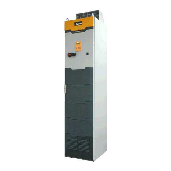
- Page 12 C h a p t e r 1 : G e t t i n g S t a r t e d AC890PX AC Drive...
- Page 13 C h a p t e r 2 : P r o d u c t O v e r v i e w C h a p t e r P r o d u c t O v e r v i e w An introduction to the AC890PX range of products, and a quick look at the Keypads and available plug-in Options.
- Page 14 C h a p t e r 2 : P r o d u c t O v e r v i e w Product Range The AC890PX AC Drive is designed to control 3-phase induction or permanent magnet AC motors, or to be used as an active front-end.
- Page 15 C h a p t e r 2 : P r o d u c t O v e r v i e w The drive is available in three voltage builds. Each build contains drives with different power ratings. Each drive has two current ratings which are selected in software as either Heavy Duty or Normal Duty The table below shows the minimum/maximum current and power for each voltage build: 400V nominal...
- Page 16 C h a p t e r 2 : P r o d u c t O v e r v i e w Component Identification 890PX (top wire entry) AC890PX AC Drive...
- Page 17 C h a p t e r 2 : P r o d u c t O v e r v i e w 890PX (bottom wire entry) AC890PX AC Drive...
- Page 18 USB-A terminal. This is for use when the drive is powered by the 3-phase supply which requires the enclosure door to be shut. Use the Parker SSD Drives’ DSE 890 (Drive Systems Explorer) Configuration Tool to graphically program and configure the drive.
- Page 19 Four diagnostic leds provide trouble- shooting information for the module. The 25-way diagnostic connector is for Auxiliary use by Parker SSD Drives' engineers. Supply CD Module AC890PX AC Drive...
- Page 20 The fan control is local to the CS Module. Four diagnostic leds provide trouble- Auxiliary shooting information for the module. Supply The 25-way diagnostic connector is for use by Parker SSD Drives' engineers. CS Module AC890PX AC Drive...
- Page 21 C h a p t e r 2 : P r o d u c t O v e r v i e w The Keypad The AC890PX AC Drive is fitted with a removable Keypad. The Keypad is used to control the drive locally. For example, you can start and stop the motor and check on diagnostic information.
- Page 22 2-10 C h a p t e r 2 : P r o d u c t O v e r v i e w AC890PX AC Drive...
- Page 23 C h a p t e r 3 : I n s t a l l i n g t h e D r i v e C h a p t e r I n s t a l l i n g t h e D r i v e This chapter describes the mechanical and electrical installation of the AC890PX AC Drive.
- Page 24 C h a p t e r 3 : I n s t a l l i n g t h e D r i v e Step 1: Mechanical Installation IMPORTANT The AC890PX is classed as a "Complete Drive Module". DO NOT install external equipment into the AC890PX enclosure.
- Page 25 C h a p t e r 3 : I n s t a l l i n g t h e D r i v e Installation Drawings Outline Drawing of AC890PX, 132kW - 400kW - HC471581 page 1 of 2 AC890PX AC Drive...
- Page 26 C h a p t e r 3 : I n s t a l l i n g t h e D r i v e Outline Drawing of AC890PX, 132kW - 400kW - HC471581 page 2 of 2 AC890PX AC Drive...
- Page 27 C h a p t e r 3 : I n s t a l l i n g t h e D r i v e Operating Conditions Drive Enclosure Information Operating Temperature 0°C to 40°C (32°F to 104°F), derate up to a maximum of 50°C Derate linearly at 1% per degree centigrade for temperature exceeding the maximum rating ambient for the drive.
- Page 28 C h a p t e r 3 : I n s t a l l i n g t h e D r i v e Drive Enclosure Information Vibration The product has been tested to the following specification: Test Fc of EN60068-2-6 10Hz<=f<=57Hz sinusoidal 0.075mm amplitude 57Hz<=f<=150Hz sinusoidal 1g...
- Page 29 C h a p t e r 3 : I n s t a l l i n g t h e D r i v e Fitting the Vent Hood Remove the rear lifting eyes from the top of the drive. Place the gasket (provided) over the hole where the vent will fit. Install the vent hood, facing either forwards or backwards.
- Page 30 C h a p t e r 3 : I n s t a l l i n g t h e D r i v e Step 2: Electrical Installation NOTE Refer to Chapter 9: "Routine Maintenance and Repair" for details of fitting a module into the drive. IMPORTANT Please read the Safety Information on page Cont.3 &...
- Page 31 C h a p t e r 3 : I n s t a l l i n g t h e D r i v e 2.1: Power Connections Top Wire Entry Isolator Control Module/Control Terminals Auxiliary Transformer Set the transformer taps - see page 3-16. Motor/Output Connections Protective Earth/Ground Internal Brake Resistor Thermal Overload Protection...
- Page 32 3-10 C h a p t e r 3 : I n s t a l l i n g t h e D r i v e Top Wire Entry Refer to Appendix C for UL wires sizes. Customers in Europe should refer to EN 60204-1 and local wiring regulations.
- Page 33 3-11 C h a p t e r 3 : I n s t a l l i n g t h e D r i v e Bottom Wire Entry Isolator Control Module/Control Terminals Auxiliary Transformer Set the transformer taps - see page 3-16. Motor/Output Connections Protective Earth/Ground Internal Brake Resistor Thermal Overload Protection...
- Page 34 3-12 C h a p t e r 3 : I n s t a l l i n g t h e D r i v e Bottom Wire Entry Refer to Appendix C for UL wires sizes. Customers in Europe should refer to EN 60204-1 and local wiring regulations.
- Page 35 3-13 C h a p t e r 3 : I n s t a l l i n g t h e D r i v e 2.1.1 Protective Earth (PE)/Ground Terminals (E) Permanent Earthing The unit must be permanently earthed according to EN 61800-5. For permanent earthing, EN 61800-5 states that: A cross-section conductor of at least 10mm²...
- Page 36 It is possible to use both the internal and external brake resistors (wired as shown) but we recommend you contact Parker SSD Drives for advice. Refer to Chapter 4: "Associated Equipment" - External Braking Resistors for help with using and selecting external brake resistors.
- Page 37 3-15 C h a p t e r 3 : I n s t a l l i n g t h e D r i v e 2.1.6 Blower Motor Thermal Overload Protection (G) The drive provides a 3-phase supply for the motor fan. The overload relay switches the power on/off.
- Page 38 3-16 C h a p t e r 3 : I n s t a l l i n g t h e D r i v e 2.1.7 Auxiliary Transformer Taps (C) The transformer is tapped for no connection, i.e. 0V - PARK when Auxiliary Transformer 40A Semi-Conductor Fuse it leaves the factory and the drive will not operate.
- Page 39 3-17 C h a p t e r 3 : I n s t a l l i n g t h e D r i v e 2.2: Control Connections WARNING During commissioning, remove the fuses (or trip the circuit breaker) on your 3-phase supply. Make sure the power is OFF, and that it cannot be switched on accidentally whilst you are working.
- Page 40 3-18 C h a p t e r 3 : I n s t a l l i n g t h e D r i v e Full Connection Diagram Connect to the control terminals. Cables must be secured together with a cable tie as close to the terminals as possible. AC890PX AC Drive...
- Page 41 3-19 C h a p t e r 3 : I n s t a l l i n g t h e D r i v e Minimum Connection Diagram Speed Reference • Connect X14/04 to a Motor Thermistor •...
- Page 42 3-20 C h a p t e r 3 : I n s t a l l i n g t h e D r i v e Mini USB Port Name Range Description This Mini USB port provides a serial communications link to a host computer running the DSE 890 Configuration Tool.
- Page 43 3-21 C h a p t e r 3 : I n s t a l l i n g t h e D r i v e FUTURE USE Name Range Description Terminal X11 is for future use. AC890PX AC Drive...
- Page 44 3-22 C h a p t e r 3 : I n s t a l l i n g t h e D r i v e ANALOG I/O Name Range Description 0V reference for analog I/O 0-10V, ±10V AIN1 Analog Input 1 (default = diff I/P +) 0-10V, ±10V...
- Page 45 24V DC 24V DC If the unit is not powering-up with 24V DC: check your supply; check your connections at X13; check the keypad is fitted correctly. If you are still experiencing problems, please contact Parker SSD Drives. AC890PX AC Drive...
- Page 46 3-24 C h a p t e r 3 : I n s t a l l i n g t h e D r i v e RELAY CONTACTS Name Range Description Relay Output: normally-open, volt-free, 24V DC 1A resistive DOUT3A 0-24V DC load or use down to 1mA, 12V levels (DOUT3 closed =...
- Page 47 3-25 C h a p t e r 3 : I n s t a l l i n g t h e D r i v e DIGITAL I/O Name Range Description DIN1 0-24V DC Digital Input 1 (default = JOG) DIN2 0-24V DC Digital Input 2 - (default = RUN)
- Page 48 3-26 C h a p t e r 3 : I n s t a l l i n g t h e D r i v e DIGITAL I/O Name Range Description DOUT4A open/closed Normally-open relay contacts, A & B. DOUT4B open/closed Default function DOUT4 closed = healthy...
- Page 49 3-27 C h a p t e r 3 : I n s t a l l i n g t h e D r i v e Step 3: Powering-Up the Unit Refer to "USER 24V DC INPUTS", page 3-23 for details about configuring and commissioning the drive without NOTE connecting 3-phase power supply.
- Page 50 3-28 C h a p t e r 3 : I n s t a l l i n g t h e D r i v e 3.2: Apply the 3-Phase Supply Fit the supply fuses and apply the 3-phase supply to the AC890PX AC Drive. 3.3: Configure the AC890PX AC Drive You must now configure the AC890PX AC Drive to your application.
- Page 51 3-29 C h a p t e r 3 : I n s t a l l i n g t h e D r i v e Configure the Drive using the Keypad Fit the keypad to the front of the unit, or connect remotely. Select LOCAL mode operation on the Keypad by pressing the L/R key (LOCAL/REMOTE) until the SETPOINT (LOCAL) parameter is displayed.
- Page 52 3-30 C h a p t e r 3 : I n s t a l l i n g t h e D r i v e Set-up Parameters The drive has several control modes: Control Modes V/Hz VOLTS / HZ Set-up as an Open-Loop Drive (V/F Fluxing) - low performance applications (fan, pump).
- Page 53 3-31 C h a p t e r 3 : I n s t a l l i n g t h e D r i v e Control Modes Set-up using 4Q Regen active front end (AFE) control mode. 4-Q REGEN DO NOT SELECT THIS CONTROL MODE FOR AC890PX.
- Page 54 3-32 C h a p t e r 3 : I n s t a l l i n g t h e D r i v e The following is a list of the Set-up parameters you may need to check before starting the drive. Set only the ones marked with "x"...
- Page 55 3-33 C h a p t e r 3 : I n s t a l l i n g t h e D r i v e SET-UP PARAMETERS PREF 6911Display Default Brief Description V/Hz PMAC 102.01 RUN STOP MODE 0 : RUN RAMP Selects the stopping mode 1 : COAST...
- Page 56 3-34 C h a p t e r 3 : I n s t a l l i n g t h e D r i v e 27.03 MOTOR BASE product code dependent Enter the motor nameplate FREQUENCY base frequency 27.04 MOTOR VOLTAGE product code dependent Enter the motor nameplate...
- Page 57 3-35 C h a p t e r 3 : I n s t a l l i n g t h e D r i v e 80.01 0 : FALSE Set TRUE to enable AUTOTUNE 1 : TRUE Autotune.
- Page 58 3-36 C h a p t e r 3 : I n s t a l l i n g t h e D r i v e 1.03 A1N1 TYPE 0 : -10..+10 V Select the input range and 1 : 0..+10 V type 2.03...
- Page 59 3-37 C h a p t e r 3 : I n s t a l l i n g t h e D r i v e Step 4: Run the Motor WARNING Remove the fuses (or trip the circuit breaker) on your 3-phase supply. Make sure the power is OFF, and that it cannot be switched on accidentally whilst you are working.
- Page 60 3-38 C h a p t e r 3 : I n s t a l l i n g t h e D r i v e Stationary or Rotating Autotune? Will the motor spin freely, i.e. not connected to a load, during the Autotune? •...
- Page 61 3-39 C h a p t e r 3 : I n s t a l l i n g t h e D r i v e Performing a Rotating Autotune NOTE The drive will not perform an Autotune when in Volts/Hz Mode (Open-Loop Drive.) An Autotune is not necessary in this control mode.
- Page 62 3-40 C h a p t e r 3 : I n s t a l l i n g t h e D r i v e Performing a Stationary Autotune The drive will not perform an Autotune when in Volts/Hz Mode (Open-Loop Drive.) An Autotune is not necessary in NOTE this control mode.
- Page 63 3-41 C h a p t e r 3 : I n s t a l l i n g t h e D r i v e Setting the Encoder Sign (Closed-Loop Vector Mode) If you have performed a Stationary Autotune in Closed-loop Vector mode, you should check the encoder direction as follows: Look and listen to the motion of the motor when the drive is running at a speed demand of between 5 - 10%.
- Page 64 3-42 C h a p t e r 3 : I n s t a l l i n g t h e D r i v e 4.2: Initial Start-Up Routines WARNING Unpredictable motion, especially if motor parameters are incorrect. Ensure no personnel are in the vicinity of the motor or any connected machinery.
- Page 65 3-43 C h a p t e r 3 : I n s t a l l i n g t h e D r i v e 3. Press the Start key . The keypad's RUN LED will light and the motor will rotate slowly (the RUN LED will flash if the setpoint is at zero).
- Page 66 3-44 C h a p t e r 3 : I n s t a l l i n g t h e D r i v e Routine 2: Remote Mode This routine assumes that the drive’s control terminals are wired as shown in "Full Connection Diagram" on page 3-18. IMPORTANT Ensure that the speed potentiometer is set to zero.
- Page 67 C h a p t e r 4 : A s s o c i a t e d E q u i p m e n t C h a p t e r A s s o c i a t e d E q u i p m e n t Details for all the ancillary parts of a system that can be used with the 890.
- Page 68 This can help the drive achieve EMC and filter thermal conformance. It also ensures longer motor life by reducing the high voltage slew rate and overvoltage stresses. Mount the filter as close to the VSD as possible. Please refer to Parker SSD Drives for the selection of a suitable filter.
- Page 69 C h a p t e r 4 : A s s o c i a t e d E q u i p m e n t External Braking Resistors Main Points ♦ We recommend using a thermal overload switch to protect the braking circuit. Refer to page 4-5. ♦...
- Page 70 C h a p t e r 4 : A s s o c i a t e d E q u i p m e n t IMPORTANT The minimum resistance of the combination and maximum dc link voltage must be as specified in Appendix E: “Technical Specifications”...
- Page 71 C h a p t e r 4 : A s s o c i a t e d E q u i p m e n t Dynamic Brake Resistor Overload Protection We recommend that the braking resistor and wire are protected by a motor circuit protector rated at 110% of the continuous current rating of the resistor(s).
- Page 72 C h a p t e r 4 : A s s o c i a t e d E q u i p m e n t Branch Circuit Protection The AC890PX is supplied with an Isolator. Branch circuit protection must be provided upstream in the 3-phase supply to the drive. Use slow-blow fuses, rated to protect the cable in the event of a short-circuit.
- Page 73 C h a p t e r 4 : A s s o c i a t e d E q u i p m e n t Circuit Breakers Circuit breakers (e.g. RCD, ELCB, GFCI), must: • Operate correctly with dc and ac protective earth currents (i.e. type B RCDs as in Amendment 2 of IEC755). •...
- Page 74 C h a p t e r 4 : A s s o c i a t e d E q u i p m e n t AC890PX AC Drive...
- Page 75 C h a p t e r 5 : O p e r a t i n g t h e D r i v e C h a p t e r O p e r a t i n g t h e D r i v e Having turned the motor for the first time, now learn about the various ways you can start and stop the drive.
- Page 76 C h a p t e r 5 : O p e r a t i n g t h e D r i v e Control Philosophy There are four ways to control the drive using Remote and Local control: Figure 3.1 Remote and Local Control Modes AC890PX AC Drive...
- Page 77 C h a p t e r 5 : O p e r a t i n g t h e D r i v e Start/Stop and Speed Control There are two forms of control in operation at any time: Start/Stop and Speed Control. Each can be individually selected to be under either Local or Remote Control.
- Page 78 C h a p t e r 5 : O p e r a t i n g t h e D r i v e Thus the drive can operate in one of four combinations of local and remote modes: Figure 3.2 The Four Combinations of Local and Remote Control NOTE...
- Page 79 C h a p t e r 5 : O p e r a t i n g t h e D r i v e The Start/Stop Mode Explained The default configuration below shows the drive in Remote control, (using the analog and digital inputs and outputs). This example will be referred to in the following explanations.
- Page 80 C h a p t e r 5 : O p e r a t i n g t h e D r i v e REVERSE Digital Input 4 SPEED SETPOINT Terminal X15/04 ACCEL TIME MAX SPEED CLAMP REMOTE SETPOINT Reference Selection Analog Input 3 Reference...
- Page 81 C h a p t e r 5 : O p e r a t i n g t h e D r i v e Start/Stop Controlled Locally The reference value is set by the SETPOINT (LOCAL) parameter. (The direction of rotation is controlled by the DIR key (forward/reverse) on the 6901 Keypad).
- Page 82 C h a p t e r 5 : O p e r a t i n g t h e D r i v e Starting and Stopping Methods NOTE Refer to Appendix D: “Programming” - REFERENCE, SEQUENCING LOGIC, REFERENCE STOP and REFERENCE RAMP, for explanations of parameters.
- Page 83 C h a p t e r 5 : O p e r a t i n g t h e D r i v e R U N i n p u t S P E E D D E M A N D R E M O T E S E T P O I N T P O W E R C IR C U IT...
- Page 84 5-10 C h a p t e r 5 : O p e r a t i n g t h e D r i v e Coast to Stop Set the SETUP::SEQ & REF::REFERENCE STOP::RUN STOP MODE parameter to COAST. In this mode the DECEL TIME ramp and the STOP TIME ramp are both ignored.
- Page 85 5-11 C h a p t e r 5 : O p e r a t i n g t h e D r i v e Advanced Stopping Methods The drive can be selected to NOT FAST STOP or to NOT COAST STOP. The stopping procedure is unaffected by Local or Remote Sequencing options.
- Page 86 5-12 C h a p t e r 5 : O p e r a t i n g t h e D r i v e Forced Coast Stop Using the Not Coast Stop mode immediately disables the power stack, causing the load to coast to a stop. The drive gives priority to the NOT COAST STOP signal.
- Page 87 5-13 C h a p t e r 5 : O p e r a t i n g t h e D r i v e The Trip Condition When a trip condition is detected, a similar stopping method to NOT COAST STOP is used. The power stack cannot be re- enabled until the trip condition has been cleared and successfully reset.
- Page 88 5-14 C h a p t e r 5 : O p e r a t i n g t h e D r i v e JOG not ignored as now stopping. Waits for stop to JOG ignored as complete before acting on JOG immediately effective already running...
- Page 89 5-15 C h a p t e r 5 : O p e r a t i n g t h e D r i v e Starting Methods The methods below can be used when the drive has the following default configurations from DSE 890 installed: Closed Loop Vector, Sensorless Vector, Shaftless Printing, Shipping, Volts/Hertz.
- Page 90 5-16 C h a p t e r 5 : O p e r a t i n g t h e D r i v e Two Wire Logic Starting Re-configure the DSE 890 default configuration(s) by connecting SETUP::SEQ & REF::SEQUENCING LOGIC::REMOTE REV OUT to SETUP::SEQ &...
- Page 91 5-17 C h a p t e r 5 : O p e r a t i n g t h e D r i v e Three Wire Logic Starting Re-configure the DSE 890 default configuration(s) by connecting SETUP::SEQ & REF::SEQUENCING LOGIC::REMOTE REV OUT to SETUP::SEQ &...
- Page 92 • Application advice is available through our Technical Support Department, who can also arrange for on-site assistance if required. Refer to the back cover of this manual for the address of your local Parker SSD Drives company. • Always use gold flash relays, or others designed for low current operation (5mA), on all control wiring.
- Page 93 100m. Motor Choke Parker SSD Drives Part Number Maximum Operating Current 250A CO471702U250 320A CO471702U320 400A CO471702U400 500A CO471702U500 600A CO471702U600 750A CO471702U750 Contact Parker SSD Drives for recommended choke values. AC890PX AC Drive...
- Page 94 5-20 C h a p t e r 5 : O p e r a t i n g t h e D r i v e Using Multiple Motors on a Single Drive A single large drive can be used to supply several smaller motors provided that each individual motor has overload protection.
- Page 95 5-21 C h a p t e r 5 : O p e r a t i n g t h e D r i v e High Starting Torque Applications requiring high motor starting torque (greater than 100% of rated torque) need careful setup of the drive voltage boost feature.
- Page 96 5-22 C h a p t e r 5 : O p e r a t i n g t h e D r i v e AC890PX AC Drive...
- Page 97 C h a p t e r 6 : T h e K e y p a d C h a p t e r T h e K e y p a d In this chapter, learn about the control keys and keypad indications. The main menu maps are shown here.
- Page 98 The 6901 Keypad is a plug-in MMI (Man-Machine Interface) option that provides local control of the drive, monitoring, and complete access for application programming. It can be used with a wide range of Parker SSD Drives' products including the 590+, 605, 650V (Frames C-F), 650 (Frames 1-3 if fitted with a RS232 port), 690+ and 890 drives.
- Page 99 C h a p t e r 6 : T h e K e y p a d Control Key Definitions Keys for Programming the Drive Navigation - Moves upwards through the list of parameters or menus Parameter - Increments the value of the displayed parameter. Command Acknowledge - Confirms action when in a command menu.
- Page 100 C h a p t e r 6 : T h e K e y p a d Keys for Operating the Drive Locally FORWARD/ Control - Changes the direction of motor rotation. Only operates when the drive is in Local REVERSE Speed Control mode.
- Page 101 C h a p t e r 6 : T h e K e y p a d Pressing the L/R key when in Remote mode takes you directly to the SETPOINT (LOCAL) parameter with the Edit mode enabled. Press the PROG key to return to the previous display. The PROG Key The PROG key toggles between the OPERATOR menu and any other menu, remembering and returning to previous positions in each menu.
- Page 102 C h a p t e r 6 : T h e K e y p a d LED Indications There are seven LEDs that indicate the status of the drive. Each LED is considered to operate in three different ways: The LEDs are labelled HEALTH, LOCAL (as SEQ and REF), RUN, STOP, FWD and FLASH REV.
- Page 103 C h a p t e r 6 : T h e K e y p a d Forward / Reverse State Requested direction and actual direction are forward Requested direction and actual direction are reverse Requested direction is forward but actual direction is reverse Requested direction is reverse but actual direction is forward LOCAL LOCAL...
- Page 104 C h a p t e r 6 : T h e K e y p a d The Menu System The unit will initialise in Remote Mode from factory conditions. The Keypad will display the Operator Menu. Each menu contains parameters.
- Page 105 C h a p t e r 6 : T h e K e y p a d The Menu System Map WELCOME SCREEN MOTOR CONTROL AUTOTUNE OPERATOR CURRENT LIMIT menu at level 1 DYNAMIC BRAKING DIAGNOSTICS ENCODER menu at level 1 ENERGY METER FEEDBACKS QUICK SETUP...
- Page 106 6-10 C h a p t e r 6 : T h e K e y p a d PHASE CONTROL FIREWIRE REF MOVE TO MASTER PHASE INCH PHASE MOVE PHASE MOVE ABS PHASE OFFSET PHASE TUNING REFERNCE ENCODER V MASTER SIMLATR VIRTUAL MASTER SEQ &...
- Page 107 6-11 C h a p t e r 6 : T h e K e y p a d Navigating the Menu System On power-up, the Keypad defaults into the OPERATOR menu, timing out scroll from the Welcome screen. You can skip the timeout by pressing the key immediately after power-up which will take you directly to the OPERATOR menu.
- Page 108 6-12 C h a p t e r 6 : T h e K e y p a d Selecting Local or Remote Mode The unit can operate in one of two ways: Remote Mode: Remote control using digital and analog inputs and outputs Local Mode: Providing local control and monitoring of the drive using the Keypad Local control keys are inactive when Remote Mode is selected.
- Page 109 6-13 C h a p t e r 6 : T h e K e y p a d How To Change a Parameter Value You can change the values of parameters stored in the OPERATOR, QUICK SETUP and SETUP menus. Refer to Chapter 7 for further information.
- Page 110 6-14 C h a p t e r 6 : T h e K e y p a d Special Menu Features Selecting the Menu Level MMI Menu Map For ease of operation there are three `viewing levels’ for the Keypad. The setting for QUICK SETUP the VIEW LEVEL parameter decides how much of the menu system will be displayed.
- Page 111 6-15 C h a p t e r 6 : T h e K e y p a d Quick Save Feature From anywhere in the menu system, hold down the PROG key for approximately 3 seconds to move quickly to the SAVE CONFIG menu.
- Page 112 6-16 C h a p t e r 6 : T h e K e y p a d Quick Tag Information With a parameter displayed, hold down the M key for approximately 3 seconds to display the parameter’s tag number (a message may be displayed during this time).
- Page 113 6-17 C h a p t e r 6 : T h e K e y p a d Password Protection MMI Menu Map When activated, the password prevents unauthorised parameter modification by making all parameters “read-only”. If you attempt to modify a password protected parameter, you SETUP will be prompted for the password.
- Page 114 6-18 C h a p t e r 6 : T h e K e y p a d To De-activate Password Protection If you try to change the value of a parameter with password protection activated, the PASSWORD screen is displayed for you to enter the current password.
- Page 115 6-19 C h a p t e r 6 : T h e K e y p a d Power-up Key Combinations Resetting to Factory Defaults (2-button reset) A special key combination restores to the drive the current product code default parameter values. This feature is only available at power-up as a security measure.
- Page 116 EXIT TO BOOT below Select from the expanded SYSTEM menu IMPORTANT We recommend the menus marked * above are only used by Parker SSD Drives or suitably qualified personnel. NOTE The LANGUAGE menu currently contains selection for ENGLISH only. AC890PX AC Drive...
- Page 117 6-21 C h a p t e r 6 : T h e K e y p a d POWER BOARD (6901 keypad) HOLD Hold down the keys opposite: PROG Power-up the drive, continue to hold for at least 2 seconds POWER DATA CORRUPT Config mode is selected,...
- Page 118 6-22 C h a p t e r 6 : T h e K e y p a d DEFAULT TO 60HZ The setting of this parameter selects the drive operating frequency. It affects those parameters whose values are dependent upon the default base frequency of the drive.
- Page 119 6-23 C h a p t e r 6 : T h e K e y p a d Remote Mounting the Keypad Fitting the Remote 6901 Keypad The 6052 Mounting Kit is required to remote-mount a 6901 Keypad. An enclosure rating of IP54 is achieved for the remote Keypad when correctly mounted using the 6052 Mounting Kit.
- Page 120 6-24 C h a p t e r 6 : T h e K e y p a d Assembly Procedure Mounting Dimensions for the Remote-Mounted 6901 Keypad AC890PX AC Drive...
- Page 121 C h a p t e r 7 : K e y p a d M e n u s C h a p t e r K e y p a d M e n u s This chapter details the Keypad menus. AC890PX AC Drive...
- Page 122 C h a p t e r 7 : K e y p a d M e n u s Keypad Menus The OPERATOR Menu OPERATOR MENU 6911 Display SETPOINT (xxxxxx) Range: —.xx % (Fixed as PREF 101.10) Indicates target speed. This will be equal to either: (Refer to the REFERENCE or REFERENCE JOG function LOCAL SETPOINT, REMOTE SETPOINT, JOG SETPOINT, COMMS blocks)
- Page 123 C h a p t e r 7 : K e y p a d M e n u s The DIAGNOSTIC Menu DIAGNOSTIC MENU PREF 6911 Display 101.09 SPEED DEMAND Range: —.xx % Indicates actual speed demand. This is the input to the frequency controller. (Refer to the REFERENCE function block) 101.01 REMOTE SETPOINT...
- Page 124 C h a p t e r 7 : K e y p a d M e n u s DIAGNOSTIC MENU PREF 6911 Display 78.18 TOTAL SPD DMD % Range: —.xx % The final value of speed demand obtained after summing all sources as a percentage of MAX SPEED CLAMP (REFERENCE function block).
- Page 125 C h a p t e r 7 : K e y p a d M e n u s DIAGNOSTIC MENU PREF 6911 Display 83.05 ACTUAL POS LIM Range: —.xx % The final actual positive torque limit as a percentage of rated motor torque. (Refer to the TORQUE LIMIT function block) 83.06 ACTUAL NEG LIM...
- Page 126 C h a p t e r 7 : K e y p a d M e n u s DIAGNOSTIC MENU PREF 6911 Display 70.13 MOTOR CURRENT A Range: —.x A This diagnostic contains the level of rms line current being drawn from the drive. (Refer to the FEEDBACKS function block) 70.02 DC LINK VOLTS...
- Page 127 C h a p t e r 7 : K e y p a d M e n u s DIAGNOSTIC MENU PREF 6911 Display 97.09 FIRST TRIP Range: Enumerated - refer to block From when a trip occurs until that trip is reset, this parameter indicates the trip source. When several trips have occurred, this parameter indicates the first one that was detected.
- Page 128 C h a p t e r 7 : K e y p a d M e n u s DIAGNOSTIC MENU PREF 6911 Display 96.07 TRIP 7 Range: Enumerated - refer to block Records the seventh most recent trip that caused the drive to stop. (Refer to the TRIPS STATUS function block) 96.08 TRIP 8...
- Page 129 C h a p t e r 7 : K e y p a d M e n u s DIAGNOSTIC MENU PREF 6911 Display 4.06 ANALOG INPUT 4 Range: —.xx % (VALUE) The input reading. (Refer to the ANALOG INPUT function block) 5.06 ANALOG INPUT 5 Range: —.xx %...
- Page 130 7-10 C h a p t e r 7 : K e y p a d M e n u s DIAGNOSTIC MENU PREF 6911 Display 13.02 DIGITAL INPUT 6 Range: FALSE / TRUE (VALUE) The TRUE or FALSE input. (Refer to the DIGITAL INPUT function block) 14.02 DIGITAL INPUT 7...
- Page 131 7-11 C h a p t e r 7 : K e y p a d M e n u s DIAGNOSTIC MENU PREF 6911 Display 18.01 DIGITAL OUTPUT 2 Range: FALSE / TRUE (VALUE) The TRUE or FALSE output demand. (Refer to the DIGITAL OUTPUT function block) 19.01 DIGITAL OUTPUT 3...
- Page 132 7-12 C h a p t e r 7 : K e y p a d M e n u s The QUICK SETUP Menu NOTE For more information about these and additional parameters accessible using the DSE Configuration Tool, refer to Appendix D or the DSE Configuration Tool on the CD supplied with your drive.
- Page 133 7-13 C h a p t e r 7 : K e y p a d M e n u s QUICK SETUP MENU PREF 6911 Display Description Range Default 27.01 CONTROL MODE This parameter contains the main method of motor 0 : VOLTS / Hz control used by the drive 1 : SENSORLESS VEC...
- Page 134 7-14 C h a p t e r 7 : K e y p a d M e n u s QUICK SETUP MENU PREF 6911 Display Description Range Default 21.01 V/F SHAPE LINEAR LAW: This gives a constant flux characteristic 0 : LINEAR LAW up to the BASE FREQUENCY 1 : FAN LAW...
- Page 135 7-15 C h a p t e r 7 : K e y p a d M e n u s QUICK SETUP MENU PREF 6911 Display Description Range Default 70.01 QUADRATIC TORQUE 0=FALSE % OF RATED MOTOR CURRENT 1=TRUE 100% overload for 30s (Heavy Duty) 150% 127.5%...
- Page 136 7-16 C h a p t e r 7 : K e y p a d M e n u s QUICK SETUP MENU PREF 6911 Display Description Range Default 21.03 * FIXED BOOST Used to correctly flux the motor at low speeds. This 0.00 to 25.00% product allows the drive to produce greater starting torque for...
- Page 137 7-17 C h a p t e r 7 : K e y p a d M e n u s QUICK SETUP MENU PREF 6911 Display Description Range Default 27.04 * ** MOTOR VOLTAGE This parameter contains the motor nameplate voltage 0.0 to 575.0V product at base frequency...
- Page 138 7-18 C h a p t e r 7 : K e y p a d M e n u s QUICK SETUP MENU PREF 6911 Display Description Range Default 27.06 * MAG CURRENT This parameter contains the motor model no-load line 0.00 to 3276.70 A product current as determined by the Autotune, or taken from...
- Page 139 7-19 C h a p t e r 7 : K e y p a d M e n u s QUICK SETUP MENU PREF 6911 Display Description Range Default 3.03 AIN 3 TYPE Selects input range for Analog Input 3. 0 = -10..+10 V 1 = 0..+10 V 2 = 0..20 mA...
- Page 140 7-20 C h a p t e r 7 : K e y p a d M e n u s The SETUP Menu This menu contains all the parameters available to you when using the DSE 890 Configuration Tool. ADVANCED view level must be selected to view this menu using the 6911 keypad.
- Page 141 C h a p t e r 8 : T r i p s & F a u l t F i n d i n g C h a p t e r T r i p s & F a u l t F i n d i n g Your drive may trip in order to protect itself.
- Page 142 C h a p t e r 8 : T r i p s & F a u l t F i n d i n g Trips What Happens when a Trip Occurs When a trip occurs, the drive’s power stage is immediately disabled causing the motor and load to coast to a stop. The trip is latched until action is taken to reset it.
- Page 143 C h a p t e r 8 : T r i p s & F a u l t F i n d i n g Resetting a Trip Condition Before a trip can be reset, the trip condition must be removed. NOTE A Heatsink Over-temperature trip may not reset immediately.
- Page 144 C h a p t e r 8 : T r i p s & F a u l t F i n d i n g Trips Table The following trips may occur to protect the drive and will be displayed on the Keypad. Keypad Description Possible Reason for Trip...
- Page 145 C h a p t e r 8 : T r i p s & F a u l t F i n d i n g Keypad Description Possible Reason for Trip Display I/O TRIPS:: INPUT 2 INPUT 2 BREAK Check configuration to determine source of signal BREAK has gone True Motor loading too great...
- Page 146 C h a p t e r 8 : T r i p s & F a u l t F i n d i n g Keypad Description Possible Reason for Trip Display Excessive load Motor voltage rating incorrect FIXED BOOST and/or AUTO BOOST set too high The motor temperature is Prolonged operation of the motor at low speed without forced...
- Page 147 Braking mode set to INTERNAL. Set to EXTERNAL and connect an External Braking Resistor if braking is required. UNKNOWN An unknown trip - refer to Parker SSD Drives One or more trips listed below have occurred with a Value greater OTHER than 32.
- Page 148 C h a p t e r 8 : T r i p s & F a u l t F i n d i n g Keypad Description Possible Reason for Trip Display The calculated value of rotor time constant is too small. Check the TR TOO SMALL value of nameplate rpm.
- Page 149 C h a p t e r 8 : T r i p s & F a u l t F i n d i n g Keypad Description Possible Reason for Trip Display See function block RESOLVER ERROR Motor current is too high description See function block I2T MOTOR TRIP...
- Page 150 8-10 C h a p t e r 8 : T r i p s & F a u l t F i n d i n g Keypad Description Possible Reason for Trip Display The current being drawn from the CS Module is too high CS Module overcurrent/ CS BRIDGE The CS Module is running too hot...
- Page 151 8-11 C h a p t e r 8 : T r i p s & F a u l t F i n d i n g Trip Groups The DISABLE WORD, ACTIVE WORD, WARNINGS WORD and TRIGGERS WORD parameters use a four digit hexadecimal number to identify individual trips.
- Page 152 Comms link. Because you are controlling the drive locally (no MMI or Comms link etc.), the unit must be returned to Parker SSD Drives for reprogramming, refer to Chapter 9: “Routine Maintenance and Repair”. However, if you have access to a keypad or suitable PC programming tool, the unit can be reset.
- Page 153 8-13 C h a p t e r 8 : T r i p s & F a u l t F i n d i n g Alert Messages A message will be displayed on the Keypad when either: •...
- Page 154 8-14 C h a p t e r 8 : T r i p s & F a u l t F i n d i n g Alert Message IDs Message Reason KEY INACTIVE Local/Remote and Jog keys inactive. DRIVE RUNNING KEY INACTIVE Run and Jog keys over ridden.
- Page 155 8-15 C h a p t e r 8 : T r i p s & F a u l t F i n d i n g Alert Message IDs Message Reason KEY INACTIVE Obsolete message NO FREE LINKS KEY INACTIVE Obsolete message LOCKED...
- Page 156 Alert displayed while changing to the setup menu on pressing the PROG key. SYSTEM Alert displayed while changing to the system menu on pressing the PROG key. SUPER USER Reserved for Parker SSD Drives. TRUE INCOMPATIBLE Power board 500v and/or underlap signals incompatible with selected product code.
- Page 157 8-17 C h a p t e r 8 : T r i p s & F a u l t F i n d i n g Alert Message IDs Message Reason INCOMPATIBLE Software is not compatible with this version of control card PCB. INCOMPATIBLE Stack has been marked as a 650 or Baldor stack POWER BOARD TYPE...
- Page 158 Faulty cabling or connections Check for problem and rectify before wrong replacing with correct fuse Faulty drive Contact Parker SSD Drives Cannot obtain HEALTH state Incorrect or no supply available Check supply details Motor will not run at switch-on Motor jammed...
- Page 159 8-19 C h a p t e r 8 : T r i p s & F a u l t F i n d i n g Module LEDs Status LED Control Module Status LED The Status LED on the Control Module may display the folowing indications.
- Page 160 8-20 C h a p t e r 8 : T r i p s & F a u l t F i n d i n g CD Module Diagnostic LEDS Diagnostic LEDs MAINS POWER CNTRL HEALTH CNTRL MAIN POWER HEALTH control power is present DC bus voltage is present...
- Page 161 8-21 C h a p t e r 8 : T r i p s & F a u l t F i n d i n g CS Module Diagnostic LEDS Diagnostic LEDs MAINS POWER CNTRL HEALTH CNTRL MAIN POWER HEALTH 50% flash - module can module is processing and...
- Page 162 8-22 C h a p t e r 8 : T r i p s & F a u l t F i n d i n g AC890PX AC Drive...
- Page 163 C h a p t e r 9 : R o u t i n e M a i n t e n a n c e & R e p a i r C h a p t e r R o u t i n e M a i n t e n a n c e &...
- Page 164 Check the condition of the air filters. Replace where necessary - Parker SSD Drives part number BO471517U001. Repair Check this Chapter for serviceable parts - complete modules, fans, fuses etc. These may be ordered from Parker SSD Drives. WARNING...
- Page 165 • Details of the fault Contact your nearest Parker SSD Drives Service Centre to arrange return of the item. You will be given a Returned Material Authorisation. Use this as a reference on all paperwork you return with the faulty item. Pack and despatch the item in the original packing materials;...
- Page 166 C h a p t e r 9 : R o u t i n e M a i n t e n a n c e & R e p a i r Module Replacement WARNING Remove the fuses (or trip the circuit breaker) on your 3-phase supply. Make sure the power is OFF, and that it cannot be switched on accidentally whilst you are working.
- Page 167 C h a p t e r 9 : R o u t i n e M a i n t e n a n c e & R e p a i r Control Module/CS Interface CD Module Fan Connector Fan Connector Auxiliary Power Supply Connector...
- Page 168 C h a p t e r 9 : R o u t i n e M a i n t e n a n c e & R e p a i r CS Module Control Module/ CP Module Fan Connector Fan Connector Auxilary Power...
- Page 169 C h a p t e r 9 : R o u t i n e M a i n t e n a n c e & R e p a i r The Control Module To remove the old module: 1.
- Page 170 C h a p t e r 9 : R o u t i n e M a i n t e n a n c e & R e p a i r AC890PX AC Drive...
- Page 171 A p p e n d i x A : O p t i o n s A p p e n d i x O p t i o n s This Chapter contains information about various options that can be fitted to the AC890PX AC Drive.
- Page 172 A p p e n d i x A : O p t i o n s Option Cards There are a range of Option Cards that may come factory-fitted to the 890PX drive, or are available for customer fitting. The options provide for fieldbus communications and speed feedback and are mounted on to the Control Board which is housed in the Control Module.
- Page 173 A p p e n d i x A : O p t i o n s Removing the Control Board WARNING Disconnect all sources of power before attempting installation. Injury or death could result from unintended actuation of controlled equipment. Allow at least 10 minutes for the drive's capacitors to discharge to safe voltage levels (<50V).
- Page 174 An enclosure for the following options can be fitted to the right hand side of the drive. 1. Input or output contactor 2. Control transformer 3. Output reactor 4. dv/dt filter for old (non-inverter) motors, or long cable runs Contact Parker SSD Drives for further information. AC890PX AC Drive...
- Page 175 A p p e n d i x B : S e q u e n c i n g L o g i c A p p e n d i x S e q u e n c i n g L o g i c The AC890PX AC Drive's reaction to commands is defined by a state machine.
- Page 176 A p p e n d i x B : S e q u e n c i n g L o g i c Principle State Machine Main Sequencing States The main sequencing state of the unit is indicated by an enumerated value given by the parameter SEQUENCER STATE under SEQUENCING LOGIC menu.
- Page 177 A p p e n d i x B : S e q u e n c i n g L o g i c SEQUENCING LOGIC Function Block - State Outputs The following table shows the states of individual parameters for the SEQUENCING LOGIC function block required to produce the condition of the MAIN SEQ STATE parameter.
- Page 178 A p p e n d i x B : S e q u e n c i n g L o g i c Transition of States The transition matrix describes what causes the transition from one state to another, for example see number 4 below: the transition from “Ready To Switch On”...
- Page 179 A p p e n d i x B : S e q u e n c i n g L o g i c Current State Next State Cause (FALSE to TRUE) Switch On Ready NOT COAST STOP = FALSE or NOT FAST STOP = FALSE Disabled Ready To Ready...
- Page 180 A p p e n d i x B : S e q u e n c i n g L o g i c S tate Diagram AC890PX AC Drive...
- Page 181 A p p e n d i x B : S e q u e n c i n g L o g i c External Control of the Drive Communications Command When sequencing is in the Remote Comms mode, the sequencing of the Drive is controlled by writing to the COMMS COMMAND (PREF 95.05).
- Page 182 A p p e n d i x B : S e q u e n c i n g L o g i c Switch On Replaces the RUN FWD, RUN REV and LATCHED RUN parameters of the SEQUENCING LOGIC function block. When Set (=1) is the same as : RUN FWD TRUE...
- Page 183 A p p e n d i x B : S e q u e n c i n g L o g i c Enable Operation ANDed with the DRIVE ENABLE parameter on the SEQUENCING LOGIC function block. When both Set (=1) is the same as: DRIVE ENABLE TRUE When either or both Cleared (= 0) is the same as :...
- Page 184 B-10 A p p e n d i x B : S e q u e n c i n g L o g i c Communications Status The COMMS STATUS parameter (PREF 95.08) in the COMMS CONTROL function block monitors the sequencing of the Drive.
- Page 185 B-11 A p p e n d i x B : S e q u e n c i n g L o g i c Ready To Switch On Same as the SWITCH ON ENABLE output parameter of the SEQUENCING LOGIC function block. Switched On Same as the SWITCHED ON output parameter of the SEQUENCING LOGIC function block.
- Page 186 B-12 A p p e n d i x B : S e q u e n c i n g L o g i c Setpoint Reached This bit is set (=1) if the Reference Ramp is not ramping. Internal Limit Active This bit is set (=1) if, while in vector control mode, the speed limit has reached the torque limit;...
- Page 187 A p p e n d i x C : C e r t i f i c a t i o n A p p e n d i x C e r t i f i c a t i o n This Chapter outlines the additional steps that may be required to achieve EMC conformance.
- Page 188 A p p e n d i x C : C e r t i f i c a t i o n Introduction Our Drives are certified as being compliant with the regulated market requirements in: Europe Drives are CE certified as being compliant with •...
- Page 189 The Declaration of Conformity signed by the companies nominated Compliance Officer is certification that the apparatus to which it refers meets the requirements of all the relevant European directives. Compliance with harmonised standards provides a "presumption of conformity” and is the route which has been adopted by Parker SSD Drives. AC890PX AC Drive...
- Page 190 However, there are so-called "Notified Bodies" under the Directive, which may be used to provide reports in response to a challenge by a national authority as to the conformity of the equipment. When installed in accordance with this manual, the AC890PX product is CE marked by Parker SSD Drives in accordance with the Low Voltage Directive...
- Page 191 A p p e n d i x C : C e r t i f i c a t i o n CE Marking for the EMC Directive 2004/108/EC The aim of the EMC Directive 2004/108/EC is to ensure that any electric or electronic device will create no more then a limited amount of RF interference such that other apparatus are not prevented from functioning correctly, also to ensure that an electric or electronic device will withstand a certain amount of Electro Magnetic interference from within its working environment.
- Page 192 Category C4; but for certification, and as an aid to builders of complex system, the emission limits and immunity levels associated with category C3 have been applied. Parker SSD Drives' certification (DoC) is supported by tests undertaken in accordance with harmonised standard BS EN61800-3...
- Page 193 The US have many municipalities that have laws, codes or regulations which require a product to be tested by a nationally recognized testing laboratory before it can be sold in their area. Parker SSD Drives adopt the nationally recognised Underwriters Laboratories (UL) mark to demonstrate compliance.
- Page 194 A p p e n d i x C : C e r t i f i c a t i o n Solid-State Short-Circuit Protection These devices are provided with Solid-State Short-Circuit (output) Protection. Integral solid state short circuit protection does not provide branch circuit protection.
- Page 195 A p p e n d i x C : C e r t i f i c a t i o n Recommended Wire Sizes North American wire sizes (AWG) are based on NEC/NFPA-70 for ampacities of thermoplastic-insulated (75ºC) copper conductors assuming not more than three current-carrying conductors in raceway or cable, based on ambient temperature of 40ºC.
- Page 196 C-10 A p p e n d i x C : C e r t i f i c a t i o n Field Grounding Terminals The field grounding terminals are identified with the International Grounding Symbol (IEC Publication 417, Symbol 5019). Operating Ambient Temperature 0°C to 40°C (32°F to 104°F), derate up to a maximum of 50°C.
- Page 197 IEC 61000-6-3 4251.1 Generic (industrial environments) EN 50081-2 IEC 61000-6-4 4251.2 Adjustable speed electrical power drive systems EN 61800-3 IEC 61800-3 Parker SSD certification (DoC) is supported by tests undertaken in accordance with harmonised standard BS EN61800-3 AC890PX AC Drive...
- Page 198 Table 17 where I ≥100A 0.15 - 0.5 0.5 - 5.0 5.0 - 30.0 Where these levels are too high and to ensure compatibility with other equipment, EMC filters are available from Parker SSD Drives. Radiated Frequency (MHz) Product Specific DB (μV)
- Page 199 C-13 A p p e n d i x C : C e r t i f i c a t i o n EMC Immunity Levels Basic standard Performance Port Phenomenon Level for test method (acceptance criterion) Enclosure port IEC 61000-4-2 4 kV CD or 8 kV AD if CD impossible...
- Page 200 C-14 A p p e n d i x C : C e r t i f i c a t i o n EMC General Installation Considerations Earthing Requirements IMPORTANT Protective earthing always takes precedence over EMC screening. Protective Earth (PE) Connections NOTE In accordance with installations to EN60204, only one protective earth conductor is permitted at each protective earth terminal contacting point.
- Page 201 C-15 A p p e n d i x C : C e r t i f i c a t i o n • Sensitive cables should cross noisy cables at 90°. • Never run sensitive cables close or parallel to the motor, dc link and braking chopper circuit for any distance. •...
- Page 202 2006/95/EC EMC Directive 2004/108/EC voltage directive for We Parker SSD Drives, address as below, declare under our We Parker SSD Drives, address as below, declare under our when the unit is used electrical equipment and sole responsibility that the above Electronic Products when...
- Page 203 A p p e n d i x D : P r o g r a m m i n g A p p e n d i x P r o g r a m m i n g This Chapter contains information about various options that can be fitted to the AC890PX AC Drive.
- Page 204 A p p e n d i x D : P r o g r a m m i n g Programming with Block Diagrams You can program the drive to your specific application. This programming simply involves changing parameter values. For instance, parameter 1 selects the main method of motor control used by the drive: Volts/Hz or Sensorless Vector.
- Page 205 A p p e n d i x D : P r o g r a m m i n g Modifying a Block Diagram • Using the keypad you can modify the parameter values within a function block. • Using the DSE Configuration Tool, you can modify the parameter values within a function block, and also make and break links within the shipping configuration.
- Page 206 A p p e n d i x D : P r o g r a m m i n g Function Block Descriptions NOTE To view the SETUP Menu, ADVANCED view level must be selected - SETUP::VIEW LEVEL. Understanding the Function Block Description The following function blocks show the parameter information necessary for programming the Drive.
- Page 207 A p p e n d i x D : P r o g r a m m i n g Function Blocks Alphabetically The function block descriptions in this chapter are arranged alphabetically, however, they are also listed below by Category. ADVANCED view level must be selected to see all the function blocks listed Page Block...
- Page 208 A p p e n d i x D : P r o g r a m m i n g Page Block Page Block Page Block Communications COMMS CONTROL FIREWIRE COMMS PORT FIREWIRE REF Trips CUSTOM TRIPS SPEED FBK TRIP TRIPS STATUS I/O TRIPS STALL TRIP...
- Page 209 A p p e n d i x D : P r o g r a m m i n g ACCESS CONTROL SETUP::MENUS::ACCESS CONTROL This function block contains options associated with keypad password protection, view levels, setpoint display and initial Operator Menu selection. Parameter Descriptions VIEW LEVEL PREF: 31.01...
- Page 210 A p p e n d i x D : P r o g r a m m i n g ANALOG INPUT SETUP::INPUTS & OUTPUTS::ANALOG INPUT The analog input block converts the input voltage or current into a value expressed as a percentage of a configurable range. Parameter Descriptions TYPE PREF: 1.03, 2.03, 3.03, 4.03...
- Page 211 A p p e n d i x D : P r o g r a m m i n g Functional Description The Drive has four analog inputs. There is an analog input function block for each: AIN1 is associated with the signal on terminal X12/02 AIN2 is associated with the signal on terminal X12/03 AIN3 is associated with the signal on terminal X12/04 AIN4 is associated with the signal on terminal X12/05...
- Page 212 D-10 A p p e n d i x D : P r o g r a m m i n g ANALOG OUTPUT SETUP::INPUTS & OUTPUTS::ANALOG OUTPUT The analog output blocks converts the demand percentage into a form suitable for driving the analog output electronics of the Drive. Parameter Descriptions VALUE PREF: 6.01, 7.01,...
- Page 213 D-11 A p p e n d i x D : P r o g r a m m i n g AUTO RESTART SETUP::SEQ & REF::AUTO RESTART Auto Restart provides the facility to automatically reset a choice of trip events and restart the Drive with a programmed number of attempts, after which, a manual or remote trip reset is required if the Drive is not successfully restarted.
- Page 214 D-12 A p p e n d i x D : P r o g r a m m i n g Parameter Descriptions INITIAL DELAY 2 PREF: 93.07 Default: —.x s Range: 0.0 to 600.0 s Determines the delay for the first restart attempt when the trip is included in TRIGGER 2. The delay is measured from all error conditions clearing.
- Page 215 D-13 A p p e n d i x D : P r o g r a m m i n g AUTOTUNE SETUP::MOTOR CONTROL::AUTOTUNE Designed for SENSORLESS VEC and CLOSED-LOOP VEC Motor Control Modes. The autotune is an automatic test sequence performed by the Drive to identify motor model parameters. The motor model is used by the Sensorless Vector and Closed-Loop Vector control modes.
- Page 216 D-14 A p p e n d i x D : P r o g r a m m i n g Parameter Descriptions TEST DISABLE PREF: 80.03 Default: Range: 0 to 4 This parameter expands on the MMI to show five tests. Each test can be individually disabled by setting to TRUE. Enumerated Value : Test 0 : STATOR RES 1 : LEAKAGE IND...
- Page 217 D-15 A p p e n d i x D : P r o g r a m m i n g Functional Description IMPORTANT You MUST carry out an Autotune if you intend to use the drive in either of the two vector control modes. If you are using it in Volts/Hz control an Autotune is not necessary.
- Page 218 D-16 A p p e n d i x D : P r o g r a m m i n g Speed Loop Autotune (MODE = 2 or 3) For these additional tests, the motor is connected to the load. •...
- Page 219 D-17 A p p e n d i x D : P r o g r a m m i n g COMMS CONTROL SETUP::SEQ & REF::COMMS CONTROL This block switches between Remote Terminal and Remote Comms operating modes. The Drive must be in Remote mode for selection to be made - REMOTE mode is enabled in the LOCAL CONTROL function block (REF MODES) and selected by the keypad.
- Page 220 D-18 A p p e n d i x D : P r o g r a m m i n g Parameter Descriptions COMMS COMMAND PREF: 95.09 Default: 0000 Range: 0x0000 to 0xFFFF 16-bit Command. Refer to Appendix B: “Sequencing Logic”. COMMS SEQ PREF: 95.06 Default: FALSE...
- Page 221 D-19 A p p e n d i x D : P r o g r a m m i n g CURRENT LIMIT SETUP::MOTOR CONTROL::CURRENT LIMIT Designed for all Motor Control Modes, except PMAC control mode. This function block allows you to set the maximum level of motor rated current (as a % of the user-set MOTOR CURRENT) which is allowed to flow before current limit action occurs.
- Page 222 D-20 A p p e n d i x D : P r o g r a m m i n g CUSTOM TRIPS SETUP::TRIPS::CUSTOM TRIPS This function block may be used to generate a trip or an alarm. The text for the trip message on the MMI may be customised. Parameter Descriptions CUSTOM ALARM 1 - 7 PREF: 165.01 to 165.07...
- Page 223 D-21 A p p e n d i x D : P r o g r a m m i n g COMMS PORT SETUP:: SEQ & REF::COMMS PORT Designed for all Motor Control Modes. This function block allows you to set the mode for the P3 Comms Port (keypad port). Parameter Descriptions MODE PREF: 129.01...
- Page 224 D-22 A p p e n d i x D : P r o g r a m m i n g DIGITAL INPUT SETUP::INPUTS & OUTPUTS::DIGITAL INPUT The digital input block converts the physical input voltage to TRUE or FALSE control signals. Parameter Descriptions VALUE PREF: 8.02, 9.02, 10.02, 11.02,...
- Page 225 D-23 A p p e n d i x D : P r o g r a m m i n g DIGITAL OUTPUT SETUP::INPUTS & OUTPUTS::DIGITAL OUTPUT The digital output block converts a logic TRUE or FALSE demand to a physical output signal. Parameter Descriptions VALUE PREF: 17.01, 18.01, 19.01...
- Page 226 D-24 A p p e n d i x D : P r o g r a m m i n g DRIVE CONFIG SETUP::DRIVE SETUP::DRIVE CONFIG This block contains general drive set-up parameters and also determines what hardware can be plugged in the A, B and F slots. These parameters must be set correctly in order for the drive to run correctly.
- Page 227 D-25 A p p e n d i x D : P r o g r a m m i n g Parameter Descriptions FBK OPT. TYPE PREF: 136.03 Default: 0 Range: See below Set this parameter to define the kind of feedback board fitted in Slot F on the drive. Enumerated Value : FBK OPT.
- Page 228 D-26 A p p e n d i x D : P r o g r a m m i n g Parameter Descriptions SLOT2 OPT. TYPE PREF: 136.05 Default: 0 Range: See below This parameter defines what kind of option board should be plugged in slot B. Enumerated Value : SLOT2 OPT.
- Page 229 D-27 A p p e n d i x D : P r o g r a m m i n g Parameter Descriptions FBK FAULT PREF: 136.07 Default: 0 Range: See below This diagnostic defines the slot F error status Enumerated Value : FBK FAULT 0 : NONE No error...
- Page 230 D-28 A p p e n d i x D : P r o g r a m m i n g Parameter Descriptions SLOT1 FAULT PREF: 136.10 Default: 0 Range: See below This diagnostic defines the slot A error status Enumerated Value : SLOT1 FAULT 0 : NONE No error...
- Page 231 D-29 A p p e n d i x D : P r o g r a m m i n g Parameter Descriptions SLOT2 FAULT PREF: 136.13 Default: 0 Range: See below This diagnostic defines the slot B error status Enumerated Value : SLOT2 FAULT 0 : NONE No error...
- Page 232 D-30 A p p e n d i x D : P r o g r a m m i n g DISPLAY SCALE SETUP::MENUS::DISPLAY SCALE These function blocks, 1 to 4, can be used to display any floating point parameter with an applied scaling factor, formulae and your preferred units. PREF 65.xx is DISPLAY SCALE 1, PREF 66.xx is DISPLAY SCALE 2, etc.
- Page 233 D-31 A p p e n d i x D : P r o g r a m m i n g Parameter Descriptions HIGH LIMIT PREF: 65.06, 66.06, 67.06, 68.06 Default: 0.00 Range: -300.00 to 300.00 Use high limit to set a maximum value for the modified parameter on the keypad. Setting the HIGH LIMIT lower than or equal to the LOW LIMIT makes the parameter “read-only”.
- Page 234 D-32 A p p e n d i x D : P r o g r a m m i n g Functional Description The DISPLAY SCALE blocks are selected in the ACCESS CONTROL and OPERATOR MENU function blocks for use with the Speed Setpoint and Operator Menu respectively.
- Page 235 D-33 A p p e n d i x D : P r o g r a m m i n g Character Sets The table below lists the characters supported by the software in decimal and hexadecimal. ’ “ &...
- Page 236 D-34 A p p e n d i x D : P r o g r a m m i n g DYNAMIC BRAKING SETUP::MOTOR CONTROL::DYNAMIC BRAKING Designed for all Motor Control Modes. The dynamic braking function block controls the rate at which energy from a regenerating motor is dumped into a resistive load. This dumping prevents the dc link voltage reaching levels which would cause an Overvoltage trip.
- Page 237 D-35 A p p e n d i x D : P r o g r a m m i n g Functional Description When enabled, the DYNAMIC BRAKING block monitors the internal dc link voltage every milli-second and sets the state of the brake switch accordingly.
- Page 238 D-36 A p p e n d i x D : P r o g r a m m i n g EMC CAPACITORS SETUP::MISCELLANEOUS::EMC CAPACITORS This block allows the user to disconnect the internal EMC "Y" capacitor (DC+ to earth and DC- to earth) from the drive earth on 890 Frames B, C &...
- Page 239 D-37 A p p e n d i x D : P r o g r a m m i n g ENCODER SETUP::MOTOR CONTROL::ENCODER This block is used to set up the way that speed feedback is obtained via the feedback option card. Different encoder types may be selected including pulse encoder, sincos encoder and absolute single turn or multi turn.
- Page 240 D-38 A p p e n d i x D : P r o g r a m m i n g Parameter Descriptions ENCODER TYPE PREF: 71.04 Default: 3 Range: See below This parameter defines the type of encoder being used. Enumerated Value : Type 0 : QUADRATURE single-ended pulse encoder...
- Page 241 D-39 A p p e n d i x D : P r o g r a m m i n g Parameter Descriptions OUTPUT GBOX IN PREF: 71.05 Default: 1 Range: 1 to +2000000000 See OUTPUT GBOX OUT below. OUTPUT GBOX OUT PREF: 71.26 Default: 1...
- Page 242 D-40 A p p e n d i x D : P r o g r a m m i n g Parameter Descriptions REV COUNT PREF: 71.15 Default: 0 Range: —. This counts the number of turns of the motor shaft. It will normally start from zero on power-up. If a multi-turn Endat encoder is fitted, REV COUNT will be made to match the multi turn encoder rev count.
- Page 243 D-41 A p p e n d i x D : P r o g r a m m i n g Functional Description A quadrature encoder uses 2 input signals (A and B), phase shifted by a quarter of a cycle (90°). Direction is obtained by looking at the combined state of A and B.
- Page 244 D-42 A p p e n d i x D : P r o g r a m m i n g ENERGY METER SETUP::MOTOR CONTROL::ENERGY METER Designed for all Motor Control Modes. This block measures the electrical energy used by the motor. Parameter Descriptions RESET PREF: 113.01...
- Page 245 D-43 A p p e n d i x D : P r o g r a m m i n g Parameter Descriptions RAW R. POWER PREF: 113.10 Default: 0.00 kVAR Range: —.xx kVAR This diagnostic shows the unfiltered estimate of reactive input power. AC890PX AC Drive...
- Page 246 D-44 A p p e n d i x D : P r o g r a m m i n g FEEDBACKS SETUP::MOTOR CONTROL::FEEDBACKS Designed for all Motor Control Modes. The FEEDBACKS block allows you to view speed feedback and motor current related diagnostics. Parameter Descriptions QUADRATIC TORQUE PREF: 70.01...
- Page 247 D-45 A p p e n d i x D : P r o g r a m m i n g Parameter Descriptions SPEED FBK RPM PREF: 70.04 Default: —.xx rpm Range: —.xx rpm This parameter changes according to the CONTROL MODE (DRIVE CONFIG function block): •...
- Page 248 D-46 A p p e n d i x D : P r o g r a m m i n g Parameter Descriptions TORQUE FEEDBACK PREF: 70.10 Default: —.xx % Range: —.xx % In PMAC Motor Control Mode, this shows the estimated motor torque as a percentage of the PERM TORQUE in the PMAC MOTOR 1 function block.
- Page 249 D-47 A p p e n d i x D : P r o g r a m m i n g FIREWIRE SETUP:: COMMS::FIREWIRE The Firewire block parameterises Firewire communications, providing a series of diagnostics. There are no user settable parameters in this block. Parameter Descriptions OWN ID PREF: 117.01...
- Page 250 D-48 A p p e n d i x D : P r o g r a m m i n g FIREWIRE REF SETUP:: PHASE CONTROL::FIREWIRE REF Performance Level = ADVANCED : CLOSED-LOOP VEC Motor Control Mode only. The FireWire option card (Option B) must be fitted to the drive. This block processes Virtual Master commands received over Firewire communications, producing position, speed and acceleration references to be used by the control loops, when Firewire is selected as the reference source (Firewire Comms Sel is TRUE in Comms Control block).
- Page 251 D-49 A p p e n d i x D : P r o g r a m m i n g Parameter Descriptions ACCEL OUTPUT PREF: 119.08 Default: —.xx Range: —.xx This diagnostic shows the acceleration demand in load mechanical Hz/s (rev/s MASTER POSITION PREF: 119.09 Default: —.xxxx deg...
- Page 252 D-50 A p p e n d i x D : P r o g r a m m i n g FLUXING SETUP::MOTOR CONTROL::FLUXING Designed for VOLTS/Hz motor Control Mode. This function block allows user parameterisation of the conventional (volts/hertz) fluxing strategy of the Drive. This is achieved though three flexible Volts-to-frequency templates.
- Page 253 D-51 A p p e n d i x D : P r o g r a m m i n g Parameter Descriptions FIXED BOOST PREF: 21.03 Default: 0.00 % Range: 0.00 to 25.00 % This parameter allows for no-load stator resistance voltage drop compensation. This correctly fluxes the motor (under no-load conditions) at low output frequencies, thereby increasing available motor torque.
- Page 254 D-52 A p p e n d i x D : P r o g r a m m i n g Parameter Descriptions USER FREQ 1 to 10 PREF: 21.10, 21.12, 21.14, 21.16, Default: Refer to Parameter Table Range: 0.0 to 100.0 % 21.18, 21.20, 21.22, 21.24, 21.26,21.28 These parameters provide 10 frequency points, which together with the USER VOLTAGE parameters, provide the user defined voltage profile.
- Page 255 D-53 A p p e n d i x D : P r o g r a m m i n g Functional Description AUTO BOOST BASE FREQUENCY MEASURED LOAD V/F SHAPE ENERGY SAVING DRIVE LINEAR LAW DEMANDED VOLTS FAN LAW BASE VOLTS ACCELERTN BOOST (x,y)
- Page 256 D-54 A p p e n d i x D : P r o g r a m m i n g V/F Shape The function block allows the user to parameterise the Drive’s conventional V/F motor fluxing scheme. Three V/F shapes are available, LINEAR LAW, FAN LAW and USER DEFINED: •...
- Page 257 D-55 A p p e n d i x D : P r o g r a m m i n g FLYCATCHING SETUP::MOTOR CONTROL::FLYCATCHING Designed for all Motor Control Modes. This block performs a directional speed search. It allows the Drive to seamlessly catch a spinning motor before controlling the motor to the desired setpoint.
- Page 258 D-56 A p p e n d i x D : P r o g r a m m i n g Parameter Descriptions SEARCH VOLTS PREF: 69.04 Default: 9.00 % Range: 0.00 to 100.00 % The percentage level of the search volts applied to the motor during the speed search phase of the flycatching sequence. Increasing this parameter improves the accuracy of the discovered motor speed but increases the braking influence of the speed search on the rotating motor.
- Page 259 D-57 A p p e n d i x D : P r o g r a m m i n g Functional Description The flycatching function enables the drive to be restarted smoothly into a spinning motor. It applies small search voltages to the motor whilst ramping the Drive frequency from maximum speed to zero.
- Page 260 D-58 A p p e n d i x D : P r o g r a m m i n g I/O TRIPS SETUP::TRIPS::I/O TRIPS This function block is designed to operate in conjunction with the Analog and Digital Input function blocks to trip the Drive on a loss of setpoint input or safety control input.
- Page 261 D-59 A p p e n d i x D : P r o g r a m m i n g Parameter Descriptions THERMISTOR PREF: 98.05 Default: FALSE Range: FALSE / TRUE The current state of the motor thermistor trip input, modified by INVERT THERMIST input. ENCODER PREF: 98.06 Default: FALSE...
- Page 262 D-60 A p p e n d i x D : P r o g r a m m i n g INERTIA COMP SETUP::MOTOR CONTROL::INERTIA COMP This block is used to provide a torque feed forward to compensate for friction and inertia effects whilst the drive is running. Parameter Descriptions FRICTN AT 0 RPM PREF: 122.01...
- Page 263 D-61 A p p e n d i x D : P r o g r a m m i n g Functional Description To Set-up Friction at 0 RPM Run the drive at a very low speed. Observe the SPEED PI OUTPUT diagnostic and set the FRICTN AT 0 RPM parameter to this value. Return to the SPEED PI OUTPUT diagnostic and verify that it is now zero, or that the noise on the diagnostic is equally positive and negative.
- Page 264 D-62 A p p e n d i x D : P r o g r a m m i n g INJ BRAKING SETUP::MOTOR CONTROL::INJ BRAKING Designed for VOLTS/Hz Motor Control Mode. The injection braking block provides a method of stopping spinning induction motors without returning the kinetic energy of the motor and load back in to the dc link of the Drive.
- Page 265 D-63 A p p e n d i x D : P r o g r a m m i n g Parameter Descriptions TIMEOUT PREF: 29.07 Default: 600.0 s Range: 0.0 to 600.0 s Determines the maximum amount of time the sequence is allowed to remain in the low frequency injection braking state. BASE VOLTS PREF: 29.08 Default: 100.00 %...
- Page 266 D-64 A p p e n d i x D : P r o g r a m m i n g INVERSE TIME PMAC SETUP::MOTOR CONTROL::INVERSE TIME PMAC Designed for PMAC control mode. The purpose of the inverse time is to automatically reduce the drive current limit in response to prolonged overload conditions (drive protection). For Frames B, C &...
- Page 267 D-65 A p p e n d i x D : P r o g r a m m i n g Parameter Descriptions AIMING POINT PREF: 162.01 Default: 105.00 % Range: 50.00 to 105.00% Determines the final level of the inverse time current limit after a period of prolonged motor overload DELAY PREF: 162.02 Default: 4.0 s...
- Page 268 D-66 A p p e n d i x D : P r o g r a m m i n g INVERSE TIME SETUP::MOTOR CONTROL::INVERSE TIME Designed for all Motor Control Modes, except PMAC control mode. The purpose of the inverse time is to automatically reduce the drive current limit in response to prolonged overload conditions. As the motor current exceeds the AIMING POINT level, the excess current is integrated.
- Page 269 D-67 A p p e n d i x D : P r o g r a m m i n g LOCAL CONTROL This block allows the available modes of Local and Remote operation to be customised. It also indicates the selected mode. You can only switch between Local and Remote modes using the Keypad.
- Page 270 D-68 A p p e n d i x D : P r o g r a m m i n g Parameter Descriptions REMOTE SEQ PREF: 94.05 Default: TRUE Range: FALSE / TRUE This parameter indicates the present source of the sequencing commands. REMOTE REF PREF: 94.06 Default: TRUE...
- Page 271 D-69 A p p e n d i x D : P r o g r a m m i n g MOT PMAC PROTECT SETUP::MOTOR CONTROL::MOT PMAC PROTECT Designed for PMAC Control Mode. This is a motor protection based on the rms current flowing in the motor phases. This protection is called I2T and is based on the permanent current and thermal time constant.
- Page 272 D-70 A p p e n d i x D : P r o g r a m m i n g Parameter Descriptions I2T INHIBIT PREF: 161.01 Default: FALSE Range: FALSE / TRUE This parameter enables/disables the I2T trip action. The drive continues to look for the motor load, but does not trip if the level is higher than 100%: FALSE : I2T trip is enabled...
- Page 273 D-71 A p p e n d i x D : P r o g r a m m i n g MOT POLARISATION SETUP::MOTOR CONTROL::MOT POLARISATION Designed for PMAC control mode This function is used to set up and verify the relative position between the position sensor and the PMAC motor. Parameter Descriptions SWITCH ON START PREF: 156.01...
- Page 274 D-72 A p p e n d i x D : P r o g r a m m i n g Parameter Descriptions 1:MOT CUR RAMP PREF: 156.07 Default: 1.00 Range: 0.10 to 20.00 s Sets the ramp value in seconds to apply to the current setpoint when the TYPE parameter is set to STANDARD.. ELEC POS OFFSET PREF: 156.16 Default:0.0000°...
- Page 275 D-73 A p p e n d i x D : P r o g r a m m i n g Functional Description The convention in the 890 drive is given below : U phase V phase W phase The correct succession of motor phases is U ( or M1 ), V ( or M2 ), W ( or M3 ) if the motor rotates in a clockwise direction looking to the motor shaft on the front side.
- Page 276 D-74 A p p e n d i x D : P r o g r a m m i n g Current MOT CURRENT PCNT MOT CURRENT RAMP To start the STANDARD polarisation: 1. The motor must be stationary, with no load attached to the motor shaft. In this method, there will be a maximum movement of half an electrical turn of the motor shaft.
- Page 277 D-75 A p p e n d i x D : P r o g r a m m i n g Examples: In U phase (90°), if ELEC POS = 20° then ELEC POS OFFSET must be set to 70° to get a value of 90° for ELEC POS. In U phase (90°), if ELEC POS = -160°...
- Page 278 D-76 A p p e n d i x D : P r o g r a m m i n g MOTOR INDUCTION SETUP::MOTOR CONTROL::MOTOR INDUCTION Designed for all Motor Control Mode, except PMAC Control Mode. In this function block you enter the details of the motor under control and any available motor nameplate information. The Autotune feature will determine the MAG CURRENT, STATOR RES, LEAKAGE INDUC, MUTUAL INDUC and ROTOR TIME CONST motor model parameter.
- Page 279 D-77 A p p e n d i x D : P r o g r a m m i n g Parameter Descriptions * NAMEPLATE RPM PREF: 27.07 Default: 1420 rpm Range: 0.0 to 30000.0 rpm This parameter contains the motor nameplate full-load rated speed. This is the motor speed in rpm at base frequency minus full load slip. * MOTOR CONNECTION PREF: 27.08 Default: 1...
- Page 280 D-78 A p p e n d i x D : P r o g r a m m i n g Parameter Descriptions LEAKAGE INDUC PREF: 27.15 Default: 33.76 mH Range: 0.00 to 300.00 mH This parameter contains the motor model per-phase leakage inductance as determined by Autotune. MUTUAL INDUC PREF: 27.16 Default: 135.02 mH...
- Page 281 D-79 A p p e n d i x D : P r o g r a m m i n g MOTOR PMAC 1 SETUP::MOTOR CONTROL::MOTOR PMAC 1 Designed for PMAC Control Mode. The MOTOR PMAC blocks (1 & 2) store all the parameters needed to run a PMAC Motor. These parameter values are entered automatically by the DSE 890 Configuration Tool when the tool is used to select the motor type.
- Page 282 D-80 A p p e n d i x D : P r o g r a m m i n g Parameter Descriptions THERM PROTECTION PREF: 134.06 Default: FALSE Range: FALSE / TRUE Motor’s thermal protection feature. ● MAX SPEED PREF: 134.07 Default: 4300 Range: 0 to INT MAX...
- Page 283 D-81 A p p e n d i x D : P r o g r a m m i n g Parameter Descriptions ● L PREF: 134.17 Default: 24.299 Range: 0.000 to 1000.000 mH Set the motor’s inductance at maximum current. This parameter is used within the current loop and is related to the overall proportional gain. PHASE PREF: 134.18 Default: 0.00...
- Page 284 D-82 A p p e n d i x D : P r o g r a m m i n g Parameter Descriptions On a PMAC motor, the ratio between the BACK EMF and the KT is always around 60: BACK EMF (Volts rms/1000rpm) ≈...
- Page 285 D-83 A p p e n d i x D : P r o g r a m m i n g Parameter Descriptions INTEGRAL FREQ PREF: 134.29 Default: 150 Range: 5 to 600 Hz This parameter defines the frequency of the Integral action of the PI corrector of the current loop. Modifying this value could induce instability.
- Page 286 D-84 A p p e n d i x D : P r o g r a m m i n g Functional Description AC890PX AC Drive...
- Page 287 D-85 A p p e n d i x D : P r o g r a m m i n g MOTOR PMAC 2 SETUP::MOTOR CONTROL::MOTOR PMAC 2 Designed for PMAC Control Mode. The MOTOR PMAC blocks (1 & 2) store all the parameters needed to run a PMAC Motor. These parameter values are entered automatically by the DSE 890 Configuration Tool when the tool is used to select the motor type.
- Page 288 D-86 A p p e n d i x D : P r o g r a m m i n g Functional Description This block defines the parameters needed to build the following curve. It is used to limit the motor’s current, depending on the speed.
- Page 289 D-87 A p p e n d i x D : P r o g r a m m i n g MOVE TO MASTER SETUP::PHASE CONTROL::MOVE TO MASTER Performance Level = ADVANCED : CLOSED-LOOP VEC Motor Control Mode only. The FireWire option card (Option B) must be fitted to the drive.
- Page 290 D-88 A p p e n d i x D : P r o g r a m m i n g Parameter Descriptions DIST TO MASTER PREF: 124.06 Default: —.xxxx Range: —.xxxx This diagnostic displays the distance (1.0 = 1 load mechanical revolution) between the load shaft position and the Master Position + Total Offset position.
- Page 291 D-89 A p p e n d i x D : P r o g r a m m i n g OP STATION SETUP::MENUS::OP STATION This block allows the operation of the Keypad control keys to be customised. Parameter Descriptions ENABLED KEYS PREF: 30.01 Default: 00F0...
- Page 292 D-90 A p p e n d i x D : P r o g r a m m i n g OPERATOR MENU SETUP::MENUS::OPERATOR MENU These function blocks, 1 to 32, are used to configure the Operator menu. This feature provides quick access to frequently used parameters. Any parameter may be “promoted”...
- Page 293 D-91 A p p e n d i x D : P r o g r a m m i n g OVER SPEED TRIP SETUP::TRIPS::OVER SPEED TRIP Designed for SENSORLESS VEC and CLOSED-LOOP VEC Motor Control Modes. The over speed trip operates by looking at speed feedback and comparing it against THRESHOLD. If the feedback exceeds this threshold for a period greater than DELAY, then a trip is triggered.
- Page 294 D-92 A p p e n d i x D : P r o g r a m m i n g PATTERN GEN SETUP::MOTOR CONTROL::PATTERN GEN Designed for all Motor Control Modes. The pattern generator function block allows you to configure the Drive PWM (Pulse Width Modulator) operation. Parameter Descriptions RANDOM PATTERN PREF: 73.01...
- Page 295 D-93 A p p e n d i x D : P r o g r a m m i n g Parameter Descriptions PWM FREQ PMAC PREF: 73.11 Default: 0 Range: See below This parameter defines the frequency of the PWM in PMAC Control mode Enumerated Value : PWM FREQ PMAC 0 : 4 kHz 1 : 8 kHz...
- Page 296 D-94 A p p e n d i x D : P r o g r a m m i n g PHASE INCH SETUP::PHASE CONTROL::PHASE INCH CLOSED-LOOP VEC Motor Control Mode only. Used with the external registration controller to advance/retard the Load reference position with respect to the Master position. Parameter Descriptions ADVANCE PREF: 108.01...
- Page 297 D-95 A p p e n d i x D : P r o g r a m m i n g Functional Description When in Phase control, the Phase Inch function block may be used to advance or retard the relative position on the slave axis with respect to the master axis.
- Page 298 D-96 A p p e n d i x D : P r o g r a m m i n g PHASE MOVE SETUP::PHASE CONTROL::PHASE MOVE Performance Level = ADVANCED : CLOSED-LOOP VEC Motor Control Mode only. The FireWire option card (Option B) must be fitted to the drive. This function block uses a position loop to stop the drive in a set distance.
- Page 299 D-97 A p p e n d i x D : P r o g r a m m i n g Parameter Descriptions ACTIVE PREF: 109.05 Default: FALSE Range: FALSE / TRUE Active is set TRUE whenever the block is enable, i.e. the move distance is none zero.. DISTANCE LEFT PREF: 109.06 Default: —.xx...
- Page 300 D-98 A p p e n d i x D : P r o g r a m m i n g Functional Description This is a simple trapezoidal relative move function, which acts on each rising edge of the Enable input. The slave shaft is moved a fixed distance at a rate given by the VELOCITY parameter.
- Page 301 D-99 A p p e n d i x D : P r o g r a m m i n g PHASE MOVE ABS SETUP::PHASE CONTROL::PHASE MOVE ABS Performance Level = ADVANCED : CLOSED-LOOP VEC Motor Control Mode only. The FireWire option card (Option B) must be fitted to the drive.
- Page 302 D-100 A p p e n d i x D : P r o g r a m m i n g Parameter Descriptions POSITION PREF: 120.05 Default: 0.0000 Range: 0.0000 to 1.0000 The absolute position demand (1.0 = 1 load mechanical revolution). VELOCITY PREF: 120.06 Default: 1.00 %...
- Page 303 D-101 A p p e n d i x D : P r o g r a m m i n g PHASE OFFSET SETUP::PHASE CONTROL::PHASE OFFSET CLOSED-LOOP VEC Motor Control Mode only. Provides an unramped position Offset of the Master reference position with respect to the Load position, or an unramped speed Offset to the Master reference speed.
- Page 304 D-102 A p p e n d i x D : P r o g r a m m i n g PHASE TUNING SETUP::PHASE CONTROL::PHASE TUNING The Tuning function block provides a means of injecting a speed offset or a phase offset in a selected wave form to assist the tuning of the speed and phase loops.
- Page 305 D-103 A p p e n d i x D : P r o g r a m m i n g Parameter Descriptions RUN TR FUNC TEST PREF: 111.12 Default: FALSE Range: FALSE / TRUE Use this parameter to start the test. Wait until the motor is turning at steady speed, then set it to TRUE. When the test is finished it will be automatically returned to FALSE.
- Page 306 D-104 A p p e n d i x D : P r o g r a m m i n g POSITION LOOP SETUP::MOTOR CONTROL::POSITION LOOP This block controls the position of the motor. It compares a position demand, with position feedback, and generates a speed demand dependent on the difference.
- Page 307 D-105 A p p e n d i x D : P r o g r a m m i n g Parameter Descriptions LIMITING PREF: 121.12 Default: FALSE Range: FALSE / TRUE This diagnostic is TRUE if the PID output has reached the Limit value. PID OUTPUT PREF: 121.09 Default: —.xxxx Hz...
- Page 308 D-106 A p p e n d i x D : P r o g r a m m i n g Functional Description The position error (position demand – position feedback) is calculated and processed by a proportional + integral (PI) controller. The output of the PI controller is a speed demand, which is passed directly to the speed loop block.
- Page 309 D-107 A p p e n d i x D : P r o g r a m m i n g POWER LOSS CNTRL SETUP::MOTOR CONTROL::POWER LOSS CNTRL Designed for all Motor Control Modes. This function block controls the behaviour of the drive during a power outage. When enabled, the drive attempts to keep the dc link high by regeneratively recovering the kinetic energy in the motor load in the event of mains supply loss.
- Page 310 D-108 A p p e n d i x D : P r o g r a m m i n g Parameter Descriptions DECEL TIME PREF: 112.05 Default: 5.00 s Range: 0.01 to 300.00 s Determines the time in which the speed setpoint is ramped to zero. This is expressed as the time to ramp from MAX SPEED to zero. INITIAL STEP PREF: 112.08 Default: 0.00 %...
- Page 311 D-109 A p p e n d i x D : P r o g r a m m i n g REFERENCE SETUP::SEQ & REF::REFERENCE This function block holds all the parameters concerning the generation of the setpoint reference (reference ramp, speed trim, setpoint reverse, etc.). The generation of reference setpoint is described in Chapter 3 : “Product Overview”...
- Page 312 D-110 A p p e n d i x D : P r o g r a m m i n g Parameter Descriptions MAX SPEED PREF: 101.08 Default: 1500 rpm Range: 0 to 32000 rpm The maximum speed clamp and scale factor for other speed parameters. 100% speed = maximum speed in rpm. SPEED DEMAND PREF: 101.09 Default: —.xx %...
- Page 313 D-111 A p p e n d i x D : P r o g r a m m i n g Functional Description Remote Reference SPEED SETPOINT MAX SPEED CLAMP sign change COMMS SETPOINT * REFERENCE SPEED DEMAND RAMP REMOTE SETPOINT SPEED TRIM MIN SPEED CLAMP...
- Page 314 D-112 A p p e n d i x D : P r o g r a m m i n g Local Reference SPEED SETPOINT MAX SPEED CLAMP sign change REFERENCE SPEED DEMAND LOCAL SETPOINT * RAMP SPEED TRIM TRIM IN LOCAL MIN SPEED CLAMP LOCAL REVERSE *...
- Page 315 D-113 A p p e n d i x D : P r o g r a m m i n g REFERNCE ENCODER SETUP::MOTOR CONTROL::REFERNCE ENCODER This block is used to set up how the reference encoder input is obtained, via the Reference Encoder Speed Feedback Option Card. This option card can be fitted to the control board in either position, upper or lower.
- Page 316 D-114 A p p e n d i x D : P r o g r a m m i n g Parameter Descriptions ENCODER INVERT PREF: 158.03 Default: FALSE Range: FALSE/TRUE This parameter is used to switch the direction of the input encoder, forward or reverse. ENCODER TYPE PREF: 158.04 Default: 0...
- Page 317 D-115 A p p e n d i x D : P r o g r a m m i n g Parameter Descriptions * OUTPUT GBOX IN PREF: 158.05 Default: 1 Range: 1 to +2000000000 See OUTPUT GBOX OUT below. * OUTPUT GBOX OUT PREF: 158.26 Default: 1...
- Page 318 D-116 A p p e n d i x D : P r o g r a m m i n g Parameter Descriptions REV COUNT PREF: 158.15 Default: 0 Range: —. This counts the number of turns of the encoder input. It will normally start from zero on power-up. If a multi-turn Endat encoder is fitted, REV COUNT will be made to match the multi-turn encoder rev count.
- Page 319 D-117 A p p e n d i x D : P r o g r a m m i n g Functional Description A quadrature encoder uses 2 input signals (A and B), phase shifted by a quarter of a cycle (90°). Direction is obtained by looking at the combined state of A and B.
- Page 320 D-118 A p p e n d i x D : P r o g r a m m i n g REFERENCE JOG SETUP::SEQ & REF::REFERENCE JOG This block holds all the parameters that concern the Jog functionality on the Drive. Parameter Descriptions SETPOINT PREF: 103.01...
- Page 321 D-119 A p p e n d i x D : P r o g r a m m i n g REFERENCE RAMP SETUP::SEQ & REF::REFERENCE RAMP This function block forms part of the reference generation. It provides the facility to control the rate at which the Drive will respond to a changing setpoint demand.
- Page 322 D-120 A p p e n d i x D : P r o g r a m m i n g Parameter Descriptions SRAMP DECEL PREF: 100.08 Default: 10.0 Range: 0.00 to 100.00 /s² This functions in the same way as SRAMP ACCEL above. SRAMP JERK 1 PREF: 100.09 Default: 10.0...
- Page 323 D-121 A p p e n d i x D : P r o g r a m m i n g Functional Description Chapter 6: “Operating the Drive” - Starting and Stopping Methods, describes the use of the system ramp. The ramp output takes the form shown below.
- Page 324 D-122 A p p e n d i x D : P r o g r a m m i n g REFERENCE STOP SETUP::SEQ & REF::REFERENCE STOP This function block holds all the parameters concerning the stopping method of the Drive. The stopping methods of the Drive are described in more detail in Chapter 6: “Operating the Drive”...
- Page 325 D-123 A p p e n d i x D : P r o g r a m m i n g Parameter Descriptions FAST STOP MODE PREF: 102.05 Default: 0 Range: See below Selects stopping mode used during a fast stop, two options ramped or coast. Enumerated Value : Stopping Mode 0 : RAMPED 1 : COAST...
- Page 326 D-124 A p p e n d i x D : P r o g r a m m i n g REGEN CONTROL SETUP::MOTOR CONTROL::REGEN CNTRL Designed for 4Q Regen Control Mode. This function block is used to setup, sequence and monitor the operation of the drive when used in 4Q Regen Control Mode. Parameter Descriptions PRECHARGE CLOSED PREF: 114.01...
- Page 327 D-125 A p p e n d i x D : P r o g r a m m i n g Parameter Descriptions CLOSE PRECHARGE PREF: 114.12 Default: TRUE Range: FALSE / TRUE This diagnostic controls the operation of the external precharge contactor required by the 4Q Regen Control Mode. ENABLE DRIVE PREF: 114.13 Default: FALSE...
- Page 328 D-126 A p p e n d i x D : P r o g r a m m i n g RESOLVER SETUP::MOTOR CONTROL::RESOLVER Designed for PMAC Control Mode. This block defines the parameters used to set up the resolver. Parameter Descriptions NAME PREF: 133.01...
- Page 329 D-127 A p p e n d i x D : P r o g r a m m i n g Parameter Descriptions RATIO PREF: 133.03 Default: 0.5 Range:0.2 to 1.0 Set the resolver’s transformation ratio (at 8kHz, nominal carrier voltage). SPEED MAX PREF: 133.04 Default: 10000...
- Page 330 D-128 A p p e n d i x D : P r o g r a m m i n g Parameter Descriptions INIT DONE PREF: 133.17 Default: TRUE Range: FALSE / TRUE This is a diagnostic output indicating the state of the resolver init sequence: INIT DONE = FALSE : init on going INIT DONE = TRUE : init done REVERSE CNT DIR...
- Page 331 D-129 A p p e n d i x D : P r o g r a m m i n g Parameter Descriptions TRIP SELECTION PREF: 133.21 Default: 2 Range: See below Select the trip detection based on hardware and/or software detection: Enumerated Value : Trip Selection 0 : HARD AND SOFT The trip is based on hardware and software detection.
- Page 332 D-130 A p p e n d i x D : P r o g r a m m i n g SEQUENCING LOGIC SETUP::SEQ & REF::SEQUENCING LOGIC This function block contains all the parameters relating to the sequencing (start and stop) of the Drive. Before the Drive will respond to the RUN FORWARD, RUN REVERSE or JOG parameters (cause the Drive to run or jog), the parameters DRIVE ENABLE, NOT FAST STOP and NOT COAST STOP need to be set to TRUE.
- Page 333 D-131 A p p e n d i x D : P r o g r a m m i n g Parameter Descriptions CONTACTOR CLOSED PREF: 92.05 Default: TRUE Range: FALSE / TRUE Feedback used to indicate that the external contactor has been closed. It must be TRUE for the sequencer to proceed from the SWITCHED ON state to the READY STATE, refer to SEQUENCER STATE.
- Page 334 D-132 A p p e n d i x D : P r o g r a m m i n g Parameter Descriptions JOGGING PREF: 92.15 Default: FALSE Range: FALSE / TRUE Indicates that the Drive is in the JOG mode. STOPPING PREF: 92.16 Default: FALSE...
- Page 335 D-133 A p p e n d i x D : P r o g r a m m i n g Parameter Descriptions SEQUENCER STATE PREF: 92.22 Default:0 Range: See below This parameter indicates the current sequencing state: Enumerated Value : State 0 : START DISABLED 1 : START ENABLED 2 : SWITCHED ON...
- Page 336 D-134 A p p e n d i x D : P r o g r a m m i n g SETPOINT DISPLAY SETUP::MENUS::SETPOINT DISPLAY This function block allows you to customise the setpoint name and setpoint parameter value. Parameter Descriptions NAME PREF: 32.02...
- Page 337 D-135 A p p e n d i x D : P r o g r a m m i n g SKIP FREQUENCIES SETUP::MOTOR CONTROL::SKIP FREQUENCIES This function block may be used to prevent the Drive operating at frequencies that cause mechanical resonance in the load. Parameter Descriptions INPUT PREF: 91.01...
- Page 338 D-136 A p p e n d i x D : P r o g r a m m i n g Parameter Descriptions OUTPUT HZ PREF: 91.11 Default: —.x Hz Range: —.x Hz Diagnostic on the output of the function block in Hz INPUT HZ PREF: 91.12 Default: —.x Hz...
- Page 339 D-137 A p p e n d i x D : P r o g r a m m i n g Functional Description Four programmable skip frequencies are available to avoid resonances within the mechanical system. Enter the value of frequency that causes the resonance using the “FREQUENCY”...
- Page 340 D-138 A p p e n d i x D : P r o g r a m m i n g The behaviour of this function block is illustrated below. D riv e F re q u e n c y S k ip b a n d S k ip F re q u e n c y S e tp o in t...
- Page 341 D-139 A p p e n d i x D : P r o g r a m m i n g SLEW RATE LIMIT SETUP::MOTOR CONTROL::SLEW RATE LIMIT Designed for all Motor Control Modes. This function block prevents over-current and over-voltage faults occurring due to a rapidly changing setpoint. Parameter Descriptions ENABLE PREF: 22.01...
- Page 342 D-140 A p p e n d i x D : P r o g r a m m i n g Functional Description The SLEW RATE LIMIT block obtains the setpoint from the output of the application, correctly scaled by the REFERENCE block. The rate of change limits are applied and the setpoint is then passed on for further processing.
- Page 343 D-141 A p p e n d i x D : P r o g r a m m i n g SLIP COMP SETUP::MOTOR CONTROL::SLIP COMP Designed for VOLTS/Hz motor Control Mode. The slip compensation function block allows the Drive to maintain motor speed in the presence of load disturbances. Parameter Descriptions ENABLE PREF: 23.01...
- Page 344 D-142 A p p e n d i x D : P r o g r a m m i n g Functional Description Based on the rated speed, the no load speed and the rated load of the motor, the slip compensation block adjusts the demand frequency to compensate for any speed reduction resulting from the load.
- Page 345 D-143 A p p e n d i x D : P r o g r a m m i n g SPEED FBK TRIP SETUP::TRIPS::SPEED FBK TRIP CLOSED-LOOP VEC Motor Control Mode only. The speed feed back trip operates by looking at speed error and comparing it against THRESHOLD. If the error exceeds this threshold for a period greater than DELAY, then a trip is triggered.
- Page 346 D-144 A p p e n d i x D : P r o g r a m m i n g SPEED LOOP SETUP::MOTOR CONTROL::SPEED LOOP Designed for SENSORLESS VEC and CLOSED-LOOP VEC Motor Control Modes. This function block controls the speed of the motor by comparing the actual speed to the demanded speed, and applying more or less torque in response to the error.
- Page 347 D-145 A p p e n d i x D : P r o g r a m m i n g Parameter Descriptions SPEED DMD FILTER PREF: 78.05 Default: 0.0 ms Range: 0.0 to 14.0 ms The speed demand is filtered to reduce ripple. The filter is first order with time constant equal to the value of this parameter. SPEED FBK FILTER PREF: 78.06 Default: 0.0 ms...
- Page 348 D-146 A p p e n d i x D : P r o g r a m m i n g Parameter Descriptions DIRECT IP SELECT PREF: 78.10 Default: 0 Range: See below The direct input to the speed loop is an analog input which is sampled synchronously with the speed loop. This ensures that the speed loop always has the most up-to-date value of the input, allowing it to respond faster.
- Page 349 D-147 A p p e n d i x D : P r o g r a m m i n g Parameter Descriptions TORQ DMD ISOLATE PREF: 78.16 Default: FALSE Range: FALSE / TRUE Selects between Speed Control mode and Torque Control mode. When TRUE, (Torque Control mode) the torque demand output from the speed loop block is the sum of the Direct Input plus the AUX TORQUE DMD parameter.
- Page 350 D-148 A p p e n d i x D : P r o g r a m m i n g Parameter Descriptions COMPENSATN TYPE PREF: 78.30 Default: 0 Range: See below Selects the type of compensation applied to the torque demand. Refer to Functional Description for selection details. Enumerated Value : Type 0 : NONE 1 : MAX ATTENUATION...
- Page 351 D-149 A p p e n d i x D : P r o g r a m m i n g Aux Torque Direct Torque Demand Input Torque Demand Isolate Limits Torque Control Torque Demand Speed Demand Speed Clamp Phase Control Lo-Pass Filter...
- Page 352 D-150 A p p e n d i x D : P r o g r a m m i n g Functional Description The speed error (speed demand minus speed feedback) is calculated and processed via a proportional + integral (PI) controller. The output of the PI controller is a torque demand, which is passed directly to the torque control block.
- Page 353 D-151 A p p e n d i x D : P r o g r a m m i n g PHASE ADVANCE This selection implements a transfer function of the type 1 + s / 2*pi*f1 , which gives a phase 1 + s / 2*pi*f2 advance between the frequencies f1 to f2.
- Page 354 D-152 A p p e n d i x D : P r o g r a m m i n g SPEED LOOP 2 SETUP::MOTOR CONTROL::SPEED LOOP 2 Designed for SENSORLESS VEC and CLOSED-LOOP VEC Motor Control Modes. There are three filters operating on the speed loop torque demand output. They add compensation to the transfer function of the motor and load. This can improve performance.
- Page 355 D-153 A p p e n d i x D : P r o g r a m m i n g Parameter Descriptions TQ COMP 2 FREQ PREF: 163.2 Default: 2000 Hz Range: 100 to 8000 Hz Performs various functions as described in Functional Description in the SPEED LOOP function block, depending on which compensation mode is selected by SELECT TQ COMP 2.
- Page 356 D-154 A p p e n d i x D : P r o g r a m m i n g STABILISATION SETUP::MOTOR CONTROL::STABILISATION Designed for VOLTS/Hz motor Control Mode. Enabling this function reduces the problem of unstable running in induction motors. This can be experienced at approximately half full speed, and under low load conditions.
- Page 357 D-155 A p p e n d i x D : P r o g r a m m i n g STALL TRIP SETUP::TRIPS::STALL TRIP The function block protects the motor from damage that may be caused by continuous operation beyond specification (i.e. in a stalled condition). Parameter Descriptions STALL TIME PREF: 105.01...
- Page 358 D-156 A p p e n d i x D : P r o g r a m m i n g TORQUE LIMIT SETUP::MOTOR CONTROL::TORQUE LIMIT Designed for all Motor Control Modes. This function block allows you to set the maximum level of motor rated torque which is allowed before torque limit action occurs. If the estimated motor torque is greater than the ACTUAL POS LIM value, the motor speed is controlled to maintain the torque at this level.
- Page 359 D-157 A p p e n d i x D : P r o g r a m m i n g TRIPS HISTORY SETUP::TRIPS::TRIPS HISTORY This function block records the last ten trips that caused the Drive to stop. To do this, it stores the value of the FIRST TRIP parameter, PREF 97:09, taken from the TRIPS STATUS function block.
- Page 360 D-158 A p p e n d i x D : P r o g r a m m i n g Functional Description This function block provides a view of the ten most recent trips that caused the Drive to stop. Every time a new trip occurs this is entered as TRIP 1 (NEWEST and the other recorded trips are moved down.
- Page 361 D-159 A p p e n d i x D : P r o g r a m m i n g TRIPS STATUS SETUP::TRIPS::TRIPS STATUS The Drive supports advanced and flexible trip logic to support monitoring of the Drive itself, the motor and the load. This function block provides a view into the current trip condition(s) and allows some trips to be disabled.
- Page 362 D-160 A p p e n d i x D : P r o g r a m m i n g Parameter Descriptions ACTIVE WORD 1 PREF: 97.05 Default: 0000 Range: 0x0000 to 0xFFFF Indicates which trips are currently active. These parameters are a coded representation of the trip status. See below for a description of how this parameter is formed.
- Page 363 D-161 A p p e n d i x D : P r o g r a m m i n g Parameter Descriptions WARNINGS WORD 4 PREF: 97.17 Default: 0000 Range: 0x0000 to 0xFFFF Indicates which conditions are likely to cause a trip. These parameters are a coded representation of the warning status. See below for a description of how this parameter is formed.
- Page 364 D-162 A p p e n d i x D : P r o g r a m m i n g Functional Description The tables below shows the possible parameter values for FIRST TRIP, and the TRIPS HISTORY function block. The DISABLED WORD 1 , ACTIVE WORD 1 and WARNINGS WORD 1 parameters use a four digit hexadecimal number to identify individual trips.
- Page 365 D-163 A p p e n d i x D : P r o g r a m m i n g The DISABLED WORD 2 , ACTIVE WORD 2 and WARNINGS WORD 2 parameters use a four digit hexadecimal number to identify individual trips.
- Page 366 D-164 A p p e n d i x D : P r o g r a m m i n g The DISABLED WORD 3 , ACTIVE WORD 3 and WARNINGS WORD 3 parameters use a four digit hexadecimal number to identify individual trips.
- Page 367 D-165 A p p e n d i x D : P r o g r a m m i n g The DISABLED WORD 4 , ACTIVE WORD 4 and WARNINGS WORD 4 parameters use a four digit hexadecimal number to identify individual trips.
- Page 368 D-166 A p p e n d i x D : P r o g r a m m i n g The DISABLED WORD 5 , ACTIVE WORD 5 and WARNINGS WORD 5 parameters use a four digit hexadecimal number to identify individual trips.
- Page 369 D-167 A p p e n d i x D : P r o g r a m m i n g The DISABLED WORD 6 , ACTIVE WORD 6 and WARNINGS WORD 6 parameters use a four digit hexadecimal number to identify individual trips.
- Page 370 D-168 A p p e n d i x D : P r o g r a m m i n g Hexadecimal Representation of Trips When more than one trip is to be represented at the same time then the trip codes are simply Decimal number Display added together to form the value displayed.
- Page 371 D-169 A p p e n d i x D : P r o g r a m m i n g VIRTUAL MASTER SETUP::PHASE CONTROL::VIRTUAL MASTER This block transmits a regular update of speed, position and acceleration to all other drives listening on the selected channel. The output is profiled by the ACCELERATION, DECELERATION and JERK 1-4 parameters.
- Page 372 D-170 A p p e n d i x D : P r o g r a m m i n g Parameter Descriptions CONTINUOUS PREF: 118.08 Default: FALSE Range: FALSE / TRUE When TRUE, it forces a smooth transition if the speed point is changed when ramping. The curve is controlled by the ACCELERATION and JERK 1 to JERK 4 parameters.
- Page 373 D-171 A p p e n d i x D : P r o g r a m m i n g Functional Description The time needed to stop or accelerate is: As the speed is symmetrical, the average speed is V/2 therefore the stopping / acceleration distance can be calculated: s V V [Meters] t V = + [Seconds]...
- Page 374 D-172 A p p e n d i x D : P r o g r a m m i n g V MASTER SIMLATR SETUP::PHASE CONTROL::V MASTER SIMLATR (Virtual Master Simulator) This function is used in conjunction with the virtual master simulator board that is fitted to the top connector on the control board.
- Page 375 D-173 A p p e n d i x D : P r o g r a m m i n g VOLTAGE CONTROL SETUP::MOTOR CONTROL::VOLTAGE CONTROL Designed for VOLTS/Hz motor Control Mode. This function block allows the motor output volts to be controlled in the presence of dc link voltage variations. This is achieved by controlling the level of PWM modulation as a function of measured dc link volts.
- Page 376 D-174 A p p e n d i x D : P r o g r a m m i n g ZERO SPEED SETUP::MOTOR CONTROL::ZERO SPEED This function block detects when the motor speed is at or close to zero. HYSTERESIS and THRESHOLD are user-definable. Parameter Descriptions HYSTERISIS PREF: 85.01...
- Page 377 D-175 A p p e n d i x D : P r o g r a m m i n g Functional Description Example where BAND = 0.2% speed demand On level 0.7% speed feedback HYSTERESIS window THRESHOLD 0.5% Off level 0.3% true zero...
- Page 378 D-176 A p p e n d i x D : P r o g r a m m i n g Parameter Specifications The headings for the Parameter tables are described below. PREF A numeric identification of the parameter. It is used to identify the source and destinations of internal links. Name The parameter name.
- Page 379 D-177 A p p e n d i x D : P r o g r a m m i n g Notes You can record your application’s settings here. Output parameters are not saved in non-volatile memory unless indicated. 1.
- Page 380 D-178 A p p e n d i x D : P r o g r a m m i n g Parameter Table: PREF Number Order PREF Name Block Type Range Default ro\rw Notes 1.03 TYPE ANALOG INPUT 1 ENUM 0 : -10..+10 V -10..+10 V...
- Page 381 D-179 A p p e n d i x D : P r o g r a m m i n g PREF Name Block Type Range Default ro\rw Notes 6.01 VALUE ANALOG OUTPUT 1 REAL -300.00 to 300.00 % 0.00 % 6.05 TYPE...
- Page 382 D-180 A p p e n d i x D : P r o g r a m m i n g PREF Name Block Type Range Default ro\rw Notes 21.01 V/F SHAPE FLUXING ENUM 0 : LINEAR LAW LINEAR LAW 1 : FAN LAW 2 : USER DEFINED 21.02...
- Page 383 D-181 A p p e n d i x D : P r o g r a m m i n g PREF Name Block Type Range Default ro\rw Notes 21.28 USER FREQ 10 FLUXING REAL 0.0 to 100.0 % 100.0 % 21.29 USER VOLTAGE 10...
- Page 384 D-182 A p p e n d i x D : P r o g r a m m i n g PREF Name Block Type Range Default ro\rw Notes 27.10 POWER FACTOR MOTOR INDUCTION REAL 0.50 to 0.99 0.86 27.11 OVERLOAD MOTOR INDUCTION...
- Page 385 D-183 A p p e n d i x D : P r o g r a m m i n g PREF Name Block Type Range Default ro\rw Notes 31.01 VIEW LEVEL ACCESS CONTROL ENUM 0 : OPERATOR BASIC 1 : BASIC 2 : ADVANCED 31.02...
- Page 386 D-184 A p p e n d i x D : P r o g r a m m i n g PREF Name Block Type Range Default ro\rw Notes 34.03 SCALING OPERATOR MENU 2 ENUM 0 : NONE NONE 1 : DISPLAY SCALE 1 2 : DISPLAY SCALE 2 3 : DISPLAY SCALE 3...
- Page 387 D-185 A p p e n d i x D : P r o g r a m m i n g PREF Name Block Type Range Default ro\rw Notes 37.01 PARAMETER OPERATOR MENU 5 PREF 00.00 to A5.15 37.02 NAME OPERATOR MENU 5 STRING...
- Page 388 D-186 A p p e n d i x D : P r o g r a m m i n g PREF Name Block Type Range Default ro\rw Notes 39.05 IGNORE PASSWORD OPERATOR MENU 7 BOOL 0 : FALSE FALSE 1 : TRUE 40.01...
- Page 389 D-187 A p p e n d i x D : P r o g r a m m i n g PREF Name Block Type Range Default ro\rw Notes 42.04 READ ONLY OPERATOR MENU 10 BOOL 0 : FALSE FALSE 1 : TRUE 42.05...
- Page 390 D-188 A p p e n d i x D : P r o g r a m m i n g PREF Name Block Type Range Default ro\rw Notes 45.03 SCALING OPERATOR MENU 13 ENUM 0 : NONE NONE 1 : DISPLAY SCALE 1 2 : DISPLAY SCALE 2 3 : DISPLAY SCALE 3...
- Page 391 D-189 A p p e n d i x D : P r o g r a m m i n g PREF Name Block Type Range Default ro\rw Notes 48.01 PARAMETER OPERATOR MENU 16 PREF 00.00 to A5.15 48.02 NAME OPERATOR MENU 16 STRING...
- Page 392 D-190 A p p e n d i x D : P r o g r a m m i n g PREF Name Block Type Range Default ro\rw Notes 50.05 IGNORE PASSWORD OPERATOR MENU 18 BOOL 0 : FALSE FALSE 1 : TRUE 51.01...
- Page 393 D-191 A p p e n d i x D : P r o g r a m m i n g PREF Name Block Type Range Default ro\rw Notes 53.04 READ ONLY OPERATOR MENU 21 BOOL 0 : FALSE FALSE 1 : TRUE 53.05...
- Page 394 D-192 A p p e n d i x D : P r o g r a m m i n g PREF Name Block Type Range Default ro\rw Notes 56.03 SCALING OPERATOR MENU 24 ENUM 0 : NONE NONE 1 : DISPLAY SCALE 1 2 : DISPLAY SCALE 2 3 : DISPLAY SCALE 3...
- Page 395 D-193 A p p e n d i x D : P r o g r a m m i n g PREF Name Block Type Range Default ro\rw Notes 59.01 PARAMETER OPERATOR MENU 27 PREF 00.00 to A5.15 59.02 NAME OPERATOR MENU 27 STRING...
- Page 396 D-194 A p p e n d i x D : P r o g r a m m i n g PREF Name Block Type Range Default ro\rw Notes 61.05 IGNORE PASSWORD OPERATOR MENU 29 BOOL 0 : FALSE FALSE 1 : TRUE 62.01...
- Page 397 D-195 A p p e n d i x D : P r o g r a m m i n g PREF Name Block Type Range Default ro\rw Notes 64.04 READ ONLY OPERATOR MENU 32 BOOL 0 : FALSE FALSE 1 : TRUE 64.05...
- Page 398 D-196 A p p e n d i x D : P r o g r a m m i n g PREF Name Block Type Range Default ro\rw Notes 66.04 COEFFICIENT B DISPLAY SCALE 2 REAL -32768.0000 to 32767.0000 1.0000 66.05 COEFFICIENT C...
- Page 399 D-197 A p p e n d i x D : P r o g r a m m i n g PREF Name Block Type Range Default ro\rw Notes 68.03 COEFFICIENT A DISPLAY SCALE 4 REAL -32768.0000 to 32767.0000 1.0000 68.04 COEFFICIENT B...
- Page 400 D-198 A p p e n d i x D : P r o g r a m m i n g PREF Name Block Type Range Default ro\rw Notes 70.05 SPEED FBK REV/S FEEDBACKS REAL _.xx 0.00 rev/s Output 70.06 SPEED FBK % FEEDBACKS...
- Page 401 D-199 A p p e n d i x D : P r o g r a m m i n g PREF Name Block Type Range Default ro\rw Notes 71.13 CALIBRATN STATUS ENCODER ENUM 0 : NOT REQUIRED Output 1 : DRIVE NOT STOPD REQUIRED 2 : MOTOR NOT STOPD...
- Page 402 D-200 A p p e n d i x D : P r o g r a m m i n g PREF Name Block Type Range Default ro\rw Notes 78.03 INT DEFEAT SPEED LOOP BOOL 0 : FALSE FALSE 1 : TRUE 78.04 SPEED INT PRESET...
- Page 403 D-201 A p p e n d i x D : P r o g r a m m i n g PREF Name Block Type Range Default ro\rw Notes 78.28 DEMAND SOURCE SPEED LOOP ENUM 0 : LOCAL REMOTE Output 1 : REMOTE 2 : COMMS...
- Page 404 D-202 A p p e n d i x D : P r o g r a m m i n g PREF Name Block Type Range Default ro\rw Notes 82.02 REGEN LIM ENABLE CURRENT LIMIT BOOL 0 : FALSE TRUE 1 : TRUE 83.01...
- Page 405 D-203 A p p e n d i x D : P r o g r a m m i n g PREF Name Block Type Range Default ro\rw Notes 91.02 BAND 1 SKIP FREQUENCIES REAL 0.0 to 500.0 Hz 0.0 Hz 91.03 FREQUENCY 1...
- Page 406 D-204 A p p e n d i x D : P r o g r a m m i n g PREF Name Block Type Range Default ro\rw Notes 92.10 REM TRIP RESET SEQUENCING LOGIC BOOL 0 : FALSE FALSE 1 : TRUE 92.11...
- Page 407 D-205 A p p e n d i x D : P r o g r a m m i n g PREF Name Block Type Range Default ro\rw Notes 92.23 REMOTE REV OUT SEQUENCING LOGIC BOOL 0 : FALSE FALSE Output 1 : TRUE...
- Page 408 D-206 A p p e n d i x D : P r o g r a m m i n g PREF Name Block Type Range Default ro\rw Notes 93.18 TRIGGER 2 WORD 4 AUTO RESTART WORD 0000 to FFFF 0000 93.19 TRIGGER 1 WORD 5...
- Page 409 D-207 A p p e n d i x D : P r o g r a m m i n g PREF Name Block Type Range Default ro\rw Notes 95.06 COMMS SEQ COMMS CONTROL BOOL 0 : FALSE FALSE Output 1 : TRUE 95.07...
- Page 410 D-208 A p p e n d i x D : P r o g r a m m i n g PREF Name Block Type Range Default ro\rw Notes 96.01 TRIP 1 (NEWEST) TRIPS HISTORY ENUM 0 : NO TRIP NO TRIP Output 1 : OVERVOLTAGE...
- Page 411 D-209 A p p e n d i x D : P r o g r a m m i n g PREF Name Block Type Range Default ro\rw Notes 96.02 TRIP 2 TRIPS HISTORY ENUM 31 : UNKNOWN NO TRIP Output 32 : OTHER 33 : MAX SPEED LOW...
- Page 412 D-210 A p p e n d i x D : P r o g r a m m i n g PREF Name Block Type Range Default ro\rw Notes 96.05 TRIP 5 TRIPS HISTORY ENUM Refer to 96.01, 96.02 NO TRIP Output 96.06...
- Page 413 D-211 A p p e n d i x D : P r o g r a m m i n g PREF Name Block Type Range Default ro\rw Notes 1 : TRUE 97.27 V PHASE FAULT TRIPS STATUS BOOL 0 : FALSE FALSE Output...
- Page 414 D-212 A p p e n d i x D : P r o g r a m m i n g PREF Name Block Type Range Default ro\rw Notes 99.05 1SEC OVER RATING DYNAMIC BRAKING REAL 1 to 40 2, 5 99.06 BRAKING...
- Page 415 D-213 A p p e n d i x D : P r o g r a m m i n g PREF Name Block Type Range Default ro\rw Notes 101.05 TRIM IN LOCAL REFERENCE BOOL 0 : FALSE FALSE 1 : TRUE 101.06 REMOTE REVERSE...
- Page 416 D-214 A p p e n d i x D : P r o g r a m m i n g PREF Name Block Type Range Default ro\rw Notes 103.02 ACCEL TIME REFERENCE JOG REAL 0.0 to 3000.0 s 1.0 s 103.03 DECEL TIME...
- Page 417 D-215 A p p e n d i x D : P r o g r a m m i n g PREF Name Block Type Range Default ro\rw Notes 109.10 OFFSET PHASE MOVE REAL _.xxxx 0.0000 Output 109.11 RESET PHASE MOVE BOOL 0 : FALSE...
- Page 418 D-216 A p p e n d i x D : P r o g r a m m i n g PREF Name Block Type Range Default ro\rw Notes 111.15 TRANSF FUNC TYPE PHASE TUNING ENUM 0 : SPEED TRANSFR FN OPEN LP 1 : OPEN LP TRANS FN TRANS FN...
- Page 419 D-217 A p p e n d i x D : P r o g r a m m i n g PREF Name Block Type Range Default ro\rw Notes 114.02 DC VOLTS DEMAND REGEN CNTRL REAL 0 to1000 V 720 V 114.09 SYNCHRONIZING...
- Page 420 D-218 A p p e n d i x D : P r o g r a m m i n g PREF Name Block Type Range Default ro\rw Notes 117.06 MCAP ADVERTS FIREWIRE Output 117.07 MAX HOPS FIREWIRE Output 117.08 OFFSET (40.69ns) FIREWIRE...
- Page 421 D-219 A p p e n d i x D : P r o g r a m m i n g PREF Name Block Type Range Default ro\rw Notes 118.18 MAX SPEED VIRTUAL MASTER REAL 100.0 to 6000.0 RPM 1500.0 RPM 118.19 STATUS...
- Page 422 D-220 A p p e n d i x D : P r o g r a m m i n g PREF Name Block Type Range Default ro\rw Notes 119.13 STATUS FIREWIRE REF ENUM 0 : READY NO FIREWIRE Output 1 : REF RESET 2 : MASTER RESET...
- Page 423 D-221 A p p e n d i x D : P r o g r a m m i n g PREF Name Block Type Range Default ro\rw Notes 121.01 PROP GAIN POSITION LOOP REAL 0.0 to 3000.0 10.0 121.02 INTEGRAL TIME POSITION LOOP...
- Page 424 D-222 A p p e n d i x D : P r o g r a m m i n g PREF Name Block Type Range Default ro\rw Notes 122.06 TORQ INERTIA COMP REAL _.xx 0.00 % Output FEEDFORWARD 122.07 SPEED PI OUTPUT INERTIA COMP...
- Page 425 D-223 A p p e n d i x D : P r o g r a m m i n g PREF Name Block Type Range Default ro\rw Notes 126.01 BAUDRATE CANOPEN ENUM 0 : 125K 1000K Output 1 : 250K 2 : 500K 3 : 1000K 126.02...
- Page 426 D-224 A p p e n d i x D : P r o g r a m m i n g PREF Name Block Type Range Default ro\rw Notes 127.03 STATUS PROFIBUS ENUM 0 : MISSING OR FAULT MISSING OR Output 1 : DISABLED FAULT...
- Page 427 D-225 A p p e n d i x D : P r o g r a m m i n g PREF Name Block Type Range Default ro\rw Notes 128.09 CNET STATE CONTROLNET ENUM 0 : NONE NONE Output 1 : FAULT 2 : INITIALISE 3 : VM CONFIGURE...
- Page 428 D-226 A p p e n d i x D : P r o g r a m m i n g PREF Name Block Type Range Default ro\rw Notes 130.07 MAC ID SOFT DEVICENET 1 to 63 0 : NO FAULT 130.08 UNRECOVER FAULT DEVICENET...
- Page 429 D-227 A p p e n d i x D : P r o g r a m m i n g PREF Name Block Type Range Default ro\rw Notes 133.21 TRIP SELECTION RESOLVER ENUM 0 : HARD AND SOFT SOFT 1 : HARD 2 : SOFT...
- Page 430 D-228 A p p e n d i x D : P r o g r a m m i n g PREF Name Block Type Range Default ro\rw Notes 134.21 MOTOR PMAC 1 REAL 0.0000 to 100.0000 Nm/A 1.3760 Nm/A 134.22 IFMB MOTOR PMAC 1...
- Page 431 D-229 A p p e n d i x D : P r o g r a m m i n g PREF Name Block Type Range Default ro\rw Notes 136.03 FBK OPT TYPE DRIVE CONFIG ENUM 0 : NONE NONE 2, 5 1 : ENCODER...
- Page 432 D-230 A p p e n d i x D : P r o g r a m m i n g PREF Name Block Type Range Default ro\rw Notes 136.05 SLOT B OPT TYPE DRIVE CONFIG ENUM 0 : NONE NONE 1 : RS485 2 : PROFIBUS...
- Page 433 D-231 A p p e n d i x D : P r o g r a m m i n g PREF Name Block Type Range Default ro\rw Notes 0 : NONE 136.09 SLOT A FITTED DRIVE CONFIG ENUM NONE Output 1 : FIREWIRE...
- Page 434 D-232 A p p e n d i x D : P r o g r a m m i n g PREF Name Block Type Range Default ro\rw Notes 136.15 PWM FREQ DRIVE CONFIG ENUM 0 : l4 KHz 4 KHz 1 : l8 KHz 136.19...
- Page 435 D-233 A p p e n d i x D : P r o g r a m m i n g PREF Name Block Type Range Default ro\rw Notes 156.14 3:SEARCH RAMP MOT POLARISATION REAL 1.00 to 50.00 s 10.00 s 156.15 3:SEARCH CURRENT...
- Page 436 D-234 A p p e n d i x D : P r o g r a m m i n g PREF Name Block Type Range Default ro\rw Notes 158.13 CALIBRATN STATUS REFERNCE ENCODER ENUM 0 : NOT REQUIRED Output 1 : DRIVE NOT STOPD REQUIRED...
- Page 437 D-235 A p p e n d i x D : P r o g r a m m i n g PREF Name Block Type Range Default ro\rw Notes 161.01 I2T INHIBIT MOT PMAC PROTECT BOOL 0 : FALSE FALSE 1 : TRUE 161.02...
- Page 438 D-236 A p p e n d i x D : P r o g r a m m i n g PREF Name Block Type Range Default ro\rw Notes 165.04 CUST ALARM 4 CUSTOM TRIPS BOOL 0 : FALSE FALSE 1 : TRUE 165.05...
- Page 439 D-237 A p p e n d i x D : P r o g r a m m i n g PREF Name Block Type Range Default ro\rw Notes 0 : UNKNOWN 177.02 STATE ETHERNET ENUM UNKNOWN Output 1 : SETUP 2 : INITIALISATION 3 : WAIT PROCESS 4 : IDLE...
- Page 440 D-238 A p p e n d i x D : P r o g r a m m i n g PREF Name Block Type Range Default ro\rw Notes 0 : UNKNOWN 178.03 STATUS PEER TO PEER ENUM UNKNOWN Output 1 : ERROR 2 : DUP PHY ADDR...
- Page 441 D-239 A p p e n d i x D : P r o g r a m m i n g Product Related Default Values The Default values in the tables below are correct for when a 2.2kW Frame B power board is fitted. * Frequency Dependent Defaults These parameter values (marked with “*”...
- Page 442 A p p e n d i x E : T e c h n i c a l S p e c i f i c a t i o n s A p p e n d i x T e c h n i c a l S p e c i f i c a t i o n s AC890PX AC Drive...
- Page 443 A p p e n d i x E : T e c h n i c a l S p e c i f i c a t i o n s Understanding the Product Code Each unit is identified using an alphanumeric code which records how the unit was configured when dispatched from the factory.
- Page 444 A p p e n d i x E : T e c h n i c a l S p e c i f i c a t i o n s Model Number Block Variable Description 89xPX Generic product: 89xPX = Modular Standalone Drive 890PX =...
- Page 445 A p p e n d i x E : T e c h n i c a l S p e c i f i c a t i o n s Model Number Block Variable Description Two characters specifying a Build Option: 00 = Not applicable on this drive 01 =...
- Page 446 A p p e n d i x E : T e c h n i c a l S p e c i f i c a t i o n s Notes for Electrical Ratings Read these notes in conjunction with the following ratings tables. IMPORTANT : The AC890PX is supplied with an in-built Reactor/AC Line Output Voltage (maximum) = Input Voltage Choke providing 3% line impedance.
- Page 447 A p p e n d i x E : T e c h n i c a l S p e c i f i c a t i o n s Electrical Ratings (380-460V) Units Maximum Prospective Short Circuit Current Nominal Input Voltage (note 2) Motor Power...
- Page 448 A p p e n d i x E : T e c h n i c a l S p e c i f i c a t i o n s Electrical Ratings (500-575V & 600-690V) Units Maximum Prospective Short Circuit Current Nominal Input Voltage (note 2) Motor Power...
- Page 449 A p p e n d i x E : T e c h n i c a l S p e c i f i c a t i o n s Spares (380-460V) 400V Nominal Input Voltage Power Supply: 3∅, 380-460Vac ±10%, 45-65Hz Control Module 890CM/A/US/00/00 890CM/A/US/00/00 890CM/A/US/00/00 890CM/A/US/00/00 890CM/A/US/00/00 890CM/A/US/00/00 890CM/A/US/00/00 Output Module LA471160U513 LA471160U513...
- Page 450 A p p e n d i x E : T e c h n i c a l S p e c i f i c a t i o n s Spares (500-575V) 600V Nominal Input Voltage Power Supply: 3∅, 500-575Vac ±10%, 45-65Hz Control Module 890CM/A/US/C6/00 890CM/A/US/C6/00 890CM/A/US/C6/00 890CM/A/US/C6/00 890CM/A/US/C6/00 Output Module LA471160U713 LA471160U713...
- Page 451 E-10 A p p e n d i x E : T e c h n i c a l S p e c i f i c a t i o n s Spares (600-690V) 700V Nominal Input Voltage Power Supply: 3∅, 600-690Vac ±10%, 45-65Hz Control Module 890CM/A/US/00/00 890CM/A/US/00/00 890CM/A/US/00/00 890CM/A/US/00/00 890CM/A/US/00/00 890CM/A/US/00/00 890CM/A/US/00/00 Output Module LA471160U713...
- Page 452 E-11 A p p e n d i x E : T e c h n i c a l S p e c i f i c a t i o n s Earthing/Safety Details Earthing Each unit must be permanently earthed according to EN 61800-5. For permanent earthing, EN 61800-5 states that: A cross-section conductor of at least 10mm²...
- Page 453 E-12 A p p e n d i x E : T e c h n i c a l S p e c i f i c a t i o n s Internal Dynamic Brake Switch Motor Brake Switch Brake Resistor Brake Switch Brake Resistor...
- Page 454 E-13 A p p e n d i x E : T e c h n i c a l S p e c i f i c a t i o n s Analog Inputs/Outputs AIN1 - AIN4, AOUT1 - AOUT2 Inputs Outputs 0-10V, ±10V, 0-20mA or 4-20mA...
- Page 455 E-14 A p p e n d i x E : T e c h n i c a l S p e c i f i c a t i o n s Digital Outputs There are six digital outputs. Two are current sourcing outputs, DINOUT1 and DINOUT2. The third is a pair of volt-free relay contacts, DOUT3A and DOUT 3B. DINOUT1, DINOUT2 ≥18V, ≤26V Output High Voltage...
- Page 456 E-15 A p p e n d i x E : T e c h n i c a l S p e c i f i c a t i o n s Relay Outputs There are three pairs of volt-free relay outputs available on Terminal X16. Rated to 230V 3A resistive load. Alternatively they may be used down to 1mA, 12V levels.
- Page 457 E-16 A p p e n d i x E : T e c h n i c a l S p e c i f i c a t i o n s Auxiliary Power Supply Requirements This tables lists the auxiliary power supply (nominal 24Vdc) requirements for the AC890PX and ancillary equipment, assuming normal operating conditions with maximum SMPS and fan loads.
- Page 458 E-17 A p p e n d i x E : T e c h n i c a l S p e c i f i c a t i o n s Fuses 380-460V Model 890PX/4/0215/.. 890PX/4/0260/.. 890PX/4/0300/.. 890PX/4/0420/..
- Page 459 E-18 A p p e n d i x E : T e c h n i c a l S p e c i f i c a t i o n s Fuses 500-690V Model 890PX/6/0130/.. 890PX/6/0160/.. 890PX/6/0190/.. 890PX/6/0280/..
- Page 460 ISS. MODIFICATION ECN No. DATE DRAWN CHK'D First release of HA471664U001 17/03/08 Small amendments. 20341 31/03/08 (20358) New Warranty Statement 20358 16/01/09 Correct use of ENABLE (X02/03) confirmed (20173) Changes to PMAC and related function blocks. V3.3 software changes. 20814 01/09/09 Add two missing parameters S12 Voltage Mode &...
Need help?
Do you have a question about the AC890PX Series and is the answer not in the manual?
Questions and answers