Table of Contents
Advertisement
Operating Manual
Plasma PSMa
Motorised Diaphragm Metering Pump
Two sets of operating instructions are required for the safe, correct and proper operation of the metering pumps: The
product-specific operating instructions and the "General Operating Instructions ProMinent
and Hydraulic Accessories".
Both sets of operating instructions are only valid when read together.
Please carefully read these operating instructions before use! · Do not discard!
The operator shall be liable for any damage caused by installation or operating errors!
Technical changes reserved.
Translation of Original operating instructions (2006/42/EC)
P_PL_0001_SW
®
Motor-Driven Metering Pumps
Vers. 10/2009
Advertisement
Table of Contents

Related Manuals for ProMinent Plasma PSMa


Summary of Contents for ProMinent Plasma PSMa
- Page 1 Motorised Diaphragm Metering Pump P_PL_0001_SW Two sets of operating instructions are required for the safe, correct and proper operation of the metering pumps: The product-specific operating instructions and the "General Operating Instructions ProMinent ® Motor-Driven Metering Pumps and Hydraulic Accessories".
- Page 2 Heidelberg ProMinent Fluid Controls India Pvt. Ltd. 2/2 M.E.S. Road Yeshwanthpur, Bangalore – 560 022 India Telephone: 080 - 2357 8872 / 73 / 74 Fax: 080 - 2357 3743 / 2347 7984 email: prominent@hpfcindia.com Internet: www.prominentindia.com BA PL 001, 1, en_GB...
- Page 3 Supplemental directives Supplementary information Please read the following supplementary information in its entirety! This information will enable you to make better use of the operating instructions. The following are highlighted separately in the document: Enumerated lists Fig. 1: Please read carefully! Operating instructions Information This provides important information relating to the...
-
Page 4: Table Of Contents
Table of contents Table of contents Identcode ................5 About this Pump ..............6 Safety Chapter ..............7 Storage, Transport and Unpacking ........10 Overview of the Unit and Control Elements ....... 12 Functional Description ............13 6.1 Drive Unit ..............13 6.2 Liquid End .............. -
Page 5: Identcode
Identcode 1 Identcode Plasma Series, Version I PSMa Type Power 05050 05065 05100 05120 05200 05260 Material of dosing head/valves PVC with EPDM sealing material Polypropylene with EPDM sealing material PTFE with PTFE sealing material Stainless steel with PTFE sealing material Dosing head design Standard Hydraulic connection... -
Page 6: About This Pump
About this Pump 2 About this Pump ProMinent ® Plasma PSMa motorised metering pumps are very effective diaphragm metering pumps. They are compact, energy- saving, provide excellent precision and reflect the high standards of quality of ProMinent motorised metering pumps. -
Page 7: Safety Chapter
Safety Chapter 3 Safety Chapter Explanation of the safety information The following signal words are used in these operating instructions to identify different severities of a hazard: Signal word Meaning WARNING Denotes a possibly hazardous situation. If this is disregarded, you are in a life-threatening situation and this can result in serious injuries. - Page 8 – Take into account the resistance of the material contacted by the chemical when selecting the feed chemical - refer to the ProMinent resistance list ® in the product equipment catalogue or at www.prominent.com .
- Page 9 Safety Chapter Information in the event of an emer‐ The pump cannot be de-energised! gency In the event of an electrical accident, disconnect the mains cable from the mains or press the emergency cut-off switch fitted on the side of the system! Should feed chemical leak out, refer to the feed chemical's safety data sheet.
-
Page 10: Storage, Transport And Unpacking
Safety information WARNING! It is prohibited to ship pumps for radioactive media! They will also not be accepted by ProMinent! WARNING! Only return metering pumps for repair in a cleaned state and with a flushed liquid end - refer to the chapter on decommissioning! Should safety precautions neverthe‐... - Page 11 Storage, Transport and Unpacking Cover the pump with a tarpaulin cover - allowing for rear venti‐ lation. Store the pump in a dry, sealed place in the following ambient condi‐ tions. Ambient Conditions Specification Value Unit Minimum storage and transport -10 °C temperature Maximum storage and transport...
-
Page 12: Overview Of The Unit And Control Elements
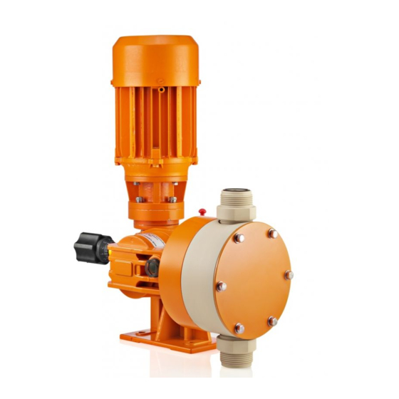
Overview of the Unit and Control Elements 5 Overview of the Unit and Control Elements P_PL_0002_SW Fig. 2: Complete overview Drive motor Bleed plug / Locking plug Liquid end Oil drain screw Drive unit Stroke length adjustment knob not shown Oil level indicator (on rear) -
Page 13: Functional Description
Functional Description 6 Functional Description 6.1 Drive Unit The metering pump is an oscillating displacement pump, the stroke length of which can be adjusted. An electric motor (1) drives the pump. A worm gear (2) reduces the drive rotation of the pump. An eccentric cam (3) converts it together with the receiving fork (8) into an oscillating movement of the driving rod (4). -
Page 14: Liquid End
Functional Description 6.2 Liquid End The diaphragm (3) hermetically closes the pump volume of the dosing head (2) towards the outside. The suction valve (4) closes as soon as the diaphragm (3) is moved in the dosing head and the feed chemical flows out of the dosing head through the discharge valve (1). -
Page 15: Assembly
Assembly 7 Assembly CAUTION! Maintenance to prevent personal and material damage Also refer to the "General Operating Instructions ProM‐ inent Motor-Driven Metering Pumps and Hydraulic ® Accessories"! CAUTION! Danger of environmental and material damage The unit can be damaged or oil may escape due to incorrect or improper storage or transportation! –... -
Page 16: Installation
Installation 8 Installation 8.1 Hydraulic Installation WARNING! Warning of feed chemical reactions to water Feed chemicals that should not come into contact with water may react to residual water in the liquid end that may originate from works testing. – Blow the liquid end dry with compressed air through the suction connector. - Page 17 Installation P_SI_0012_SW Fig. 6: Direction of rotation of motor – Key motor data can be found on the unit specification label. The terminal wiring diagram is located in the terminal – box. The motor can only be wired in star (Y) configura‐ –...
-
Page 18: Commissioning
Commissioning 9 Commissioning Safety information CAUTION! Maintenance to prevent personal and material damage Also refer to the "General Operating Instructions ProM‐ inent Motor-Driven Metering Pumps and Hydraulic ® Accessories"! Fitting the bleed plug CAUTION! Possible environmental and material damage The locking screw on the oil filling opening is factory- fitted and, during operation, prevents any pressure compensation between the drive housing and the surroundings. - Page 19 Commissioning Correctly adjusting the pump: Select as large a stroke length as possible for viscous feed chemicals. Select as large a stroke length as possible for outgassing feed chemicals. Select as high a stroke rate as possible for good mixing. Do not set the stroke length at less than 30 % for precise dosing.
-
Page 20: Maintenance
Maintenance 10 Maintenance WARNING! It is mandatory that you read the safety information and specifications in the "Storage, Transport and Unpacking" chapter prior to shipping the pump. CAUTION! Warning of feed chemical spraying around Feed chemical can spray out of the hydraulic compo‐ nents if they are manipulated or opened due to pressure in the liquid end and adjacent parts of the system. - Page 21 Maintenance Tightening torque Specification Value Unit Tightening torque for screws: 9.0 Nm...
-
Page 22: Repair
Repair 11 Repair Safety information WARNING! It is mandatory that you read the safety information and specifications in the "Storage, Transport and Unpacking" chapter prior to shipping the pump. WARNING! Contact with the feed chemical Parts that come into contact with the feed chemical become uncovered and touched during repairs. - Page 23 Repair P_SI_0013_SW Fig. 9: Simple cross-section through ball valve Flat seal Valve body Valve ball Valve seat Valve cap...
-
Page 24: Replacing The Diaphragm
Repair 11.2 Replacing the Diaphragm WARNING! Depending on the design, a few cubic centimetres of feed chemical may have accumulated behind the diaphragm in the backplate following a leak! – Take this feed chemical into consideration when you are planning a repair - especially if it is hazardous! Personnel: Technical personnel If necessary take protective measures. - Page 25 Repair – Check the tightening torque of the screws after 24- hours of operation! – Recheck the tightening torque again after three months with PP dosing heads! Tightening torque Specification Value Unit Tightening torque for screws: 9.0 Nm...
-
Page 26: Troubleshooting
Troubleshooting 12 Troubleshooting Safety information WARNING! Warning of hazardous or unknown feed chemical Should a hazardous or unknown feed chemical be used, it may escape from the hydraulic components when working on the pump. – Take appropriate protective measures before working on the pump (protective eyewear, protective gloves, ...). -
Page 27: Decommissioning
Decommissioning 13 Decommissioning Decommissioning WARNING! Danger from chemical residues There is normally chemical residue in the liquid end and on the housing after operation. This chemical residue could be hazardous to individuals. – It is mandatory that the safety information relating to the "Storage, Transport and Unpackaging"... - Page 28 Decommissioning Additional work: refer to the chapter on "Storage, Transport and Unpacking". Disposal Personnel: Technical personnel CAUTION! Environmental hazard due to gear oil The pump contains gear oil that can cause damage to the environment. – Drain the gear oil from the pump. –...
-
Page 29: Technical Data
Technical Data 14 Technical Data 14.1 Performance Data Plasma with 0.2 kW motor, 400 V, 50 Hz, 1440 rpm Type Minimum flow rate at maximum back Maximum Stroke Suction lift Connector pressure stroke rate length size ml/stroke Strokes/ m WS G-DN 05050 1 1/4"... -
Page 30: Ambient Conditions
Technical Data Safety requirements Degree of protection: 1 - Mains power connection with protective earth conductor 14.3 Ambient Conditions 14.3.1 Temperatures Pump, compl. Specification Value Unit Storage and transport temperature -10 ... +50 °C Ambient temperature in operation -10 ... +45 °C (drive): PP liquid end Specification... -
Page 31: Climate
Technical Data 14.3.2 Climate Specification Value Unit Maximum air humidity *: 95 % rel. humidity * non-condensing 14.4 Gear Oil Manufacturer Name Viscosity class Oil volume (ISO 3442) Shell Omala HD 0.25 l 14.5 Sound Pressure Level Sound Pressure Level The sound pressure level is <... -
Page 32: Appendix
P_PL_0007_SW Fig. 10: Dimensional drawing of Plasma PSMa - dimensions in mm Dimensional drawing of Plasma without motor 90 x 63 1 1/4" BSP Ø 9 P_PL_0008_SW Fig. 11: Dimensional drawing of Plasma PSMa without motor - dimensions in mm... -
Page 33: Diagrams For Setting The Metering Capacity
Appendix 15.2 Diagrams for Setting the Metering Capacity C [l/h] PSMa 05050 C [l/h] PSMa 05065 s [%] s [%] C [l/h] C [l/h] p [bar] p [bar] C [l/h] PSMa 05120 C [l/h] PSMa 05090 s [%] s [%] C [l/h] C [l/h] p [bar]... -
Page 34: Ordering Information
Appendix C [l/h] PSMa 05260 C [l/h] PSMa 05200 s [%] s [%] C [l/h] C [l/h] p [bar] p [bar] Fig. 13: A) Metering capacity C at medium back pressure according to the stroke length for maximum stroke rate. B) Metering capacity C at medium back pressure according to the back pressure p. 15.3 Ordering Information 15.3.1 Spare Parts Sets Spare parts sets normally include the wearing parts of a liquid end. -
Page 35: Diaphragms
FM 260 - DN 20 PMIN-3303006 FM 260 - DN 20 PMIN-3303007 FM 260 - DN 20 PMIN-3303008 PMIN = Heidelberg ProMinent Fluid Controls India Pvt. Ltd. 15.3.2 Diaphragms Diaphragms for types 05050, 05065 Liquid end Part no. FM 130... -
Page 36: Ec Declaration Of Conformity
Appendix 15.4 EC Declaration of Conformity Fig. 14... -
Page 37: Decontamination Declaration
Appendix 15.5 Decontamination Declaration Declaration of Decontamination (see download: www.prominent.com) Because of legal regulations and for the safety of our employees and operation equipment, we need the „declara- tion of decontamination”, with your signature, before your order can be handled. -
Page 38: Index
Index 16 Index About this Pump ............ 6 Leakage hole ............20 Accuracy ............. 29 Liquid end ............12 Air humidity ............31 Liquid End ............14 Ambient Conditions ..........30 Locking screw ............. 12 Appendix ............. 32 Assembly ............. 15 Maintenance ............
Need help?
Do you have a question about the Plasma PSMa and is the answer not in the manual?
Questions and answers