Table of Contents
Advertisement
Quick Links
tM-752N Series
User Manual
Tiny Addressable Serial Converter
S
UPPORTS
Module includes tM-7521 and tM-7522.
W
ARRANTY
All products manufactured by ICP DAS are warranted against defective
materials for a period of one year from the date of delivery to the
original purchaser.
W
ARNING
ICP DAS assumes no liability for damages consequent to the use of this
product. ICP DAS reserves the right to change this manual at any time
without notice. The information furnished by ICP DAS is believed to be
accurate and reliable. However, no responsibility is assumed by ICP DAS
for its use, nor for any infringements of patents or other rights of third
parties resulting from its use.
C
OPYRIGHT
Copyright © 2017 by ICP DAS. All rights are reserved.
T
RADEMARK
Names are used for identification only and may be registered
trademarks of their respective companies.
C
U
ONTACT
S
If you have any question, please feel to contact us. We will give you
quick response within 2 workdays.
Email: service@icpdas.com, service.icpdas@gmail.com
ICP DAS CO., LTD.
Ver. 1.3/ Apr. 2018
User Manual, Ver. 1.3, Apr. 2018, Page: 1
Advertisement
Table of Contents

Subscribe to Our Youtube Channel
Related Manuals for ICP DAS USA tM-752N Series


Summary of Contents for ICP DAS USA tM-752N Series
- Page 1 Series User Manual Tiny Addressable Serial Converter Ver. 1.3/ Apr. 2018 UPPORTS Module includes tM-7521 and tM-7522. ARRANTY All products manufactured by ICP DAS are warranted against defective materials for a period of one year from the date of delivery to the original purchaser.
-
Page 2: Table Of Contents
Tiny Addressable Serial Converter ABLE OF ONTENTS PACKING LIST..............................4 MORE INFORMATION ............................4 1.INTRODUCTION ..............................5 RS-232 C DDRESSABLE ONVERTER ASIC I UNER NSIDE ....................... 6 1KB Q NBOARD UEUE UFFER ........................6 ERVER ......................6 ............................7 2. HARDWARE INFORMATION ......................... 8 PECIFICATIONS EATURES ............................ - Page 3 Tiny Addressable Serial Converter HANGE ASSWORD OGOUT ..........................34 ............................. 34 5. COMMAND SETS ............................35 OMMAND ABLE ........................35 5.1.1 $AAA[addr] ........................... 36 5.1.2 $AABN[baud rate] ........................37 5.1.3 $AADN[data-bit] ........................... 39 5.1.4 $AAPN[parity-bit] ......................... 41 5.1.5 $AAON[stop-bit] ........................... 43 5.1.6 $AA6[name] ..........................
-
Page 4: Packing List
Tiny Addressable Serial Converter ACKING The shipping package includes the following items: Note: If any of these items are missing One tM-752N series hardware module or damaged, please contact the One printed Quick Start Guide local distributor for more One DC Connector Power cable ... -
Page 5: Introduction
The devices are usually located at a distance from the Host PC, meaning that linking via multiple serial cards is inefficient. ICPDAS tM-752N series products have been developed to provide an effective link between multiple RS-232 devices via a single RS-485 network. -
Page 6: Addressable Rs-232 Converter
1.3 Onboard 1KB Queue Buffer tM-752N series modules are equipped with a 1KB queue buffer for its local serial port. All input data can be stored in the queue buffer until the Host PC has time to read it. These features allow the Host PC to be linked to thousands of RS-232 devices without any loss of data. -
Page 7: Web Server
Tiny Addressable Serial Converter 1.4 Web Server Web server enables configuration of the tM-752N via a standard web browser interface, e.g. Internet Explorer, Firefox or Mozilla, etc. This means that it is easy to check the configuration of thetM-752Nvia web interface instead of using console commands, thereby reducing the user’s learning curve. -
Page 8: Hardware Information
Tiny Addressable Serial Converter 2. Hardware Information 2.1 Specifications Model tM-7521 tM-7522 System 32-bit MCU Communication Interface 10/100 Base-TX, 8-pin RJ-45 x 1, Ethernet (Auto-negotiating, Auto-MDI/MDIX, LED indicator) PoE (IEEE 802.3af, Class 1) COM1 2-wire RS-485 2-wire RS-485 COM2 5-wire RS-232 3-wire RS-232 COM3 3-wire RS-232... -
Page 9: Features
Tiny Addressable Serial Converter 2.2 Features Built-in “Addressable RS-232 Converter” firmware Contains a powerful 32-bit MCU 10/100 Base-TX Ethernet, RJ-45 x1 (Auto-negotiating, auto MDI/MDIX, LED Indicators) Includes redundant power inputs: PoE (IEEE 802.3af, Class 1) and DC jack ... -
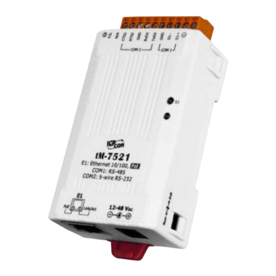
Page 10: Front View
Tiny Addressable Serial Converter 2.4 Front View Here is a brief overview of the tM-752N series module components and a description. J2 Connector 3. S1: System LED Indicator Robust insulated and fire retardant case 4. Operating Mode Switch 2. +12 ~ +48 V Jack 1. - Page 11 Tiny Addressable Serial Converter 1. PoE and Ethernet RJ-45 Jack: The tM-752N is equipped with a RJ-45 jack that is used as the 10/100 Base-TX Ethernet port and features networking capability. When an Ethernet link is detected and an Ethernet packet is received, the Link/Act LED (Orange) indicator will be illuminated.
- Page 12 Init Mode: Uses factory settings and allows firmware update. Run Mode: Uses customer settings. In the tM-752N series, the operating mode Switch is in the Run position by default. When updating the tM-752N firmware, the switch needs to be moved from the Run position to the Init position.
-
Page 13: Dimensions
Tiny Addressable Serial Converter 2.5 Dimensions The following diagrams provide the dimensions of thetM-7521/tM-7522and CA-002 cable that can be used as a reference when defining the specifications and the DC power supply plug for any custom enclosures. All dimensions are in millimeters. tM-7521/7522 Module: ... - Page 14 Tiny Addressable Serial Converter CA-002 Cable Note: Cable color: BLACK Pin Assignment DESCRIPTION UNIT UL2464 18AWG 2C(RED/BLACK) 0D5.0 COLOR BLACK OPEN DC PLUG 5.5*2.1 BLACK OPEN PVC:45/P BLACK ICP DAS CO., LTD. User Manual, Ver. 1.3, Apr. 2018, Page: 14...
-
Page 15: Pin Assignments
Tiny Addressable Serial Converter 2.6 Pin Assignments tM-7521 Pin Assignments 1-Port 2-Wire RS-485 and 1-Port 5-Wire RS-232 Module tM-7522 Pin Assignments 1-Port 2-Wire RS-485 and 2-Port 3-Wire RS-232 Module ICP DAS CO., LTD. User Manual, Ver. 1.3, Apr. 2018, Page: 15... -
Page 16: Wiring Notes
Tiny Addressable Serial Converter 2.7 Wiring Notes RS-232 Wiring Connection Note: 1. For 3-Wire RS-232 connections, it is recommended that unused signals such as RTS/CTS and DTR/DSR are shorted, since some systems may still check the status of CTS and DSR. 2. -
Page 17: Setting Up The Tm-752N
Tiny Addressable Serial Converter 3. Setting up the tM-752N Prepare for device: Hub/Switch: NS-205PSE or NS-205 (optional) Isolated RS-232 to RS-422/485 converter module: I-7520 module (optional) Step 1: Connecting the power and Host PC Check Init/Run switch is on “Run”... - Page 18 Tiny Addressable Serial Converter PoE Power Supply 3. Perform a test wiring check as follows: Wiring to RS-232 Device Wiring to host PC Via the RS-485 bus ICP DAS CO., LTD. User Manual, Ver. 1.3, Apr. 2018, Page: 18...
-
Page 19: Tep Earch For The T M-752N
Tiny Addressable Serial Converter 4. Connecting to Multiple Remote RS-232 Devices as follows: Step 2: Run the eSearch Utility The eSearch Utility can be obtained from our FTP site: http://ftp.icpdas.com/pub/cd/tinymodules/napdos/software/esearch/ Double-click the eSearch.exe ICP DAS CO., LTD. User Manual, Ver. 1.3, Apr. 2018, Page: 19... -
Page 20: 4: Configure The Network Settings
Click the “Search Servers” button to search for your tM-752N module. Step 4: Configure the network settings 1. tM-752N series module is IP-based devices that may not be suitable for your network using a default IP address. Therefore, you must first assign a new IP address to the tM- 752N module depending on your network settings. - Page 21 Tiny Addressable Serial Converter 2. Contact your Network Administrator to obtain the correct network configuration information such as IP/Mask/Gateway. Enter the network settings and then click “OK”. The tM-752N will use the new settings within 2 seconds. 3. Wait 2 seconds and then click the “Search Servers” button again to ensure that the tM- 752N is working correctly with the new configuration.
- Page 22 Tiny Addressable Serial Converter Step 5: Testing your tM-752N module 1. Execute your hyper terminal program or our “Terminal.exe”. The Terminal.exe can be obtained from our FTP site: http://ftp.icpdas.com/pub/cd/tinymodules/napdos/software/ 2. Check that the configuration of the COM Port is correct and then click the “Open COM” button.
-
Page 23: Web Configuration
Tiny Addressable Serial Converter 4. Web Configuration The tM-752N module can be configured via serial port (refer to chapter 5) and also can be configured via web browser after its network is setting and functioning correctly. 4.1 Logging on to the tM-752N Web Server You can log onto the tM-752N web server from any computer that has Internet access. - Page 24 Tiny Addressable Serial Converter Step 3: Enter the password After entering the IP address, the login dialog page will be displayed. Enter the password, and then click the “Submit” button to enter the configuration web page. The factory default password is: Item Default admin...
-
Page 25: Home Page
Tiny Addressable Serial Converter 4.2 Home Page The Home link connects to the main page, which contains two parts. The first part of this page provides basic information about the tM-752N hardware and software. The second part of this page provides the status of the port settings. ICP DAS CO., LTD. -
Page 26: Etwork Etting
Tiny Addressable Serial Converter 4.3 Network Setting 4.3.1 Network and Miscellaneous Settings Check the model name and the software information. The software information includes the following items: Firmware Version, Model Name, IP Address, Initial Switch, MAC Address, and System Timeout. - Page 27 Tiny Addressable Serial Converter Item Descriptions: Item Description Static IP: If you don’t have a DHCP server in your network, you can configure the network settings manually. Please refer to the Section “4.3.2.1 Manually Configuration” Address Type DHCP/AutoIP: Dynamic Host Configuration Protocol (DHCP) is a network application protocol that automatically assigns an IP address to each device.
- Page 28 Tiny Addressable Serial Converter Network settings can be configured using either dynamic configuration or manual configuration, as per the following instructions: Manual Configuration When using manual configuration, you have to assign all the network settings in the following manner: Step 1: Select “Static IP” as the address type Step 2: Enter the appropriate network settings Step 3: Click the “Update Settings”...
-
Page 29: General Configuration Settings
Tiny Addressable Serial Converter 4.3.3 General Configuration Settings The General Configuration Settings provides functions allowing items such as the Alias Name, System Timeout value, and Auto-logout value to be configured. Item Descriptions: Item Description Default System Address A module address (Net ID) for tM-752N module Add a checksum in the last field of message Enable Checksum 0 = Disable (default);... -
Page 30: Restore Factory Defaults
Tiny Addressable Serial Converter 4.3.4 Restore Factory Defaults To reset the settings to their factory defaults, follow these steps: Step 1: Click the “Restore Defaults” button to reset the configuration. Step 2: Click the “OK” button in the message dialog box. Step 3: Check whether the tM-752N is reset to factory default settings for use with the eSearch.exe. -
Page 31: Erial Ort Ettings
Tiny Addressable Serial Converter 4.4 Serial Port Settings 4.4.1 Port1 Settings Check the tM-752N hardware and software information. The port settings provide the following functions: These are 5 modes in ending-chars pattern. Mode 0: 0x0D ; Mode 1: 0x0D,0x0A ; Mode 2: 0x0A,0x0D ; Mode 3: 0x0A ; Mode 4: No Ending-Chars;... - Page 32 Tiny Addressable Serial Converter Item Descriptions: Item Description Default Baud Rate (bps) Sets the Baud Rate for the COM ports. 115200 Data Size (bits) Sets the Data Size for the COM ports. Parity Sets the Parity for the COM ports. None Stop Bits (bits) Sets the Stop Bits for the COM ports.
-
Page 33: Filter
Tiny Addressable Serial Converter 4.5 Filter For detailed network and miscellaneous settings description, refer to section 4.3.1 “Network and Miscellaneous Settings”. 4.5.1 Filter Settings This filter settings page is used to query or edit IP filter list. The IP filter list restricts the access of packets based on the IP header. -
Page 34: Change Password
Tiny Addressable Serial Converter 4.6 Change Password Item Descriptions: Item Description Current password Enter the old password (default is admin) New password Enter the new password Confirm new password Enter the new password again Submit Click this button to save the new settings to the tM-752N. 4.7 Logout Click the “Logout “tag to logout from the system and return to the login page. -
Page 35: Command Sets
Tiny Addressable Serial Converter 5. Command Sets 5.1 Command Sets Table Address Table (“AA” means the modules address) Model Module Address COM1 Address COM2 Address COM3 Address tM-7521 tM-7522 AA+1 Command Sets Table: Section Command Response Description 5.1.1 $AAA[addr] Read/Set the module Address 5.1.2... -
Page 36: Aaa[Addr]
Tiny Addressable Serial Converter 5.1.1 $AAA[addr] Description: This function reads/sets the module address. Syntax: $AAA[chk](CrLf) Reads the module address stored in the Flash $AAA[addr][chk](CrLf) Sets the module address [Request] Byte 1 Byte 2-3 Byte 4 Byte 5-6 Byte 7-8 Byte 9-10 Note Read... -
Page 37: Aabn[Baud Rate]
Tiny Addressable Serial Converter 5.1.2 $AABN[baud rate] Description: This function reads/sets the Baud Rate for COM 1/2/3. Syntax: Reads the Baud Rate for COM 1/2/3 stored in the Flash $AABN[chk](CrLf) $AABN[baud rate][chk](CrLf) Sets the Baud rate for COM 1/ 2/ 3 [Request] Byte 1 Byte 2-3... - Page 38 Tiny Addressable Serial Converter Example: (Assume the module address of tM-752N is 01) e.g. Command Response $01B0(CrLf) !0157600(CrLf) Read the COM1 (RS-485) Baud Rate. $01B19600(CrLf) !01(CrLf) Changes the COM2 (RS-232) Baud Rate to 9600 bps. $02B138400(CrLf) !02(CrLf) Changes the COM3 (RS-232) Baud Rate to 38400 bps. ICP DAS CO., LTD.
-
Page 39: Aadn[Data-Bit]
Tiny Addressable Serial Converter 5.1.3 $AADN[data-bit] Description: This function reads/sets the data bit for COM 1/2/3. Syntax: Reads the data bit for COM 1/2/3 stored in the Flash $AADN[chk](CrLf) $AADN[data-bit][chk](CrLf) Sets the data bit for COM 1/2/3 [Request] Byte 1 Byte 2-3 Byte 4... - Page 40 Tiny Addressable Serial Converter Example: (Assume the module address of tM-752N is 01) e.g. Command Response $01D08(CrLf) !01(CrLf) Changes the data bit to 8 for the COM1 (RS-485) $01D17(CrLf) !01(CrLf) Changes the data bit to 7 for the COM2 (RS-232) $02D17(CrLf) !02(CrLf) Changes the data bit to 7 for the COM3 (RS-232)
-
Page 41: Aapn[Parity-Bit]
Tiny Addressable Serial Converter 5.1.4 $AAPN[parity-bit] Description: This function reads/sets the parity bit for COM 1/2/3. Syntax: Reads the parity bit for COM 1/2/3 stored in the Flash $AAPN[chk](CrLf) $AAPN[parity-bit][chk](CrLf) Sets the parity bit for COM 1/2/3 [Request] Byte 1 Byte 2-3 Byte 4... - Page 42 Tiny Addressable Serial Converter Example: (Assume the module address of tM-752N is 01) e.g. Command Response $01P00(CrLf) !01(CrLf) Changes parity-bit to NONE for COM1 (RS-485) $01P10(CrLf) !01(CrLf) Changes parity-bit to NONE for COM2 (RS-232) $02P11(CrLf) !02(CrLf) Changes parity-bit to EVEN for COM3 (RS-232) ICP DAS CO., LTD.
-
Page 43: Aaon[Stop-Bit]
Tiny Addressable Serial Converter 5.1.5 $AAON[stop-bit] Description: This function reads/sets the stop bit for COM 1/2/3. Syntax: Reads the stop bit of COM 3 stored in the Flash $AAON[chk](CrLf) $AAON[stop-bit][chk](CrLf) Sets the stop bit for COM 3 [Request] Byte 1 Byte 2-3 Byte 4... - Page 44 Tiny Addressable Serial Converter Example: (Assume the module address of tM-752N is 01) e.g. Command Response $01O12(CrLf) !02(CrLf) Changes the stop bit to 2 for the COM2 (RS-232) $02O12(CrLf) !03(CrLf) Changes the stop bit to 2 of the COM3 (RS-232) ICP DAS CO., LTD.
-
Page 45: Aa6[Name]
Tiny Addressable Serial Converter 5.1.6 $AA6[name] Description: This function sets the alias-name string for COM 2/3. Max-number of characters = 15. Syntax: Sets the alias-name string for COM 2/3 $AA6[ID][chk](CrLf) [Request] Byte 1 Byte 2-3 Byte 4 Byte 5-12 Byte 13-14 Byte 15-16 [name]... -
Page 46: Aa7
Tiny Addressable Serial Converter 5.1.7 $AA7 Description: This function reads the alias-name string for COM 2/3. Syntax: Reads the alias-name string for COM 2/3 $AA7[chk](CrLf) [Request] Byte 1 Byte 2-3 Byte 4 Byte 5-6 Byte 7-8 [chk] (CrLf) Delimiter character 2-character port address in Hex format. -
Page 47: Aac[Delimiter]
Tiny Addressable Serial Converter 5.1.8 $AAC[delimiter] Description: This reads/sets the delimiter for COM 2/3. Syntax: Reads the delimiter for COM 2/3 stored in the Flash $AAC[chk](CrLf) Sets the delimiter for COM 2/3 $AAC[delimiter][chk](CrLf) [Request] Byte 1 Byte 2-3 Byte 4 Byte 5-6 Byte 7-8... - Page 48 Tiny Addressable Serial Converter Example: (Assume the module address of tM-752N is 01) e.g. Command Response $01C(CrLf) !01:(CrLf) Reads the delimiter for the COM2 (RS-232) $02C*(CrLf) !02:(CrLf) Changes the delimiter for the COM3 (RS-232) Notes: (1) The delimiter of COM 2/3 can be different. (2) The default delimiter is “...
-
Page 49: Delimiter]Aa[Bypass]
Tiny Addressable Serial Converter 5.1.9 [delimiter]AA[bypass] Description: This function bypasses the data string to COM 2/3. Syntax: Bypasses the data string to COM 2/3 (delimiter)AA(pass)[chk](CrLf) [Request] Byte 1 Byte 2-3 Byte 4 - n Byte (n+1) - (n+2) Byte (n+3) - (n+4) (delimiter) (bypass) -
Page 50: Aakv
Tiny Addressable Serial Converter 5.1.10 $AAKV Description: This function reads/sets the checksum status. Syntax: Reads the checksum status stored in the Flash $AAK[chk](CrLf) Sets the checksum status $AAKV[chk](CrLf) [Request] Byte 1 Byte 2-3 Byte 4 Byte 5-6 Byte 7-8 Note [chk] (CrLf) - Page 51 Tiny Addressable Serial Converter Example: (Assume the module address of tM-752N is 01.) e.g. Command Response $01K000(CrLf) !0182(CrLf) Disables the checksum chk: 00,82 $01K1(CrLf) !01(CrLf) The checksum is enabled Notes: The checksum enable/disable function is valid for COM1, since the checksum is used in communication between tm-752N and host PC.
-
Page 52: Aatn[Crlfmode]
Tiny Addressable Serial Converter 5.1.11 $AATN[CrLfmode] Description: This function reads/sets what the characters are as judging the end of command or response string. Syntax: Reads the setting value of CrLfmode stored in the Flash $AATN[chk](CrLf) Sets the setting value of CrLfmode for the $AATN(CrLfmode)[chk](CrLf) command/response string [Request]... - Page 53 Tiny Addressable Serial Converter [Response] Byte 1 Byte 2-3 Byte 4 Byte 5-6 Byte 7-8 Note [CrLfmode] [chk] (CrLf) Read Byte 1 Byte 2-3 Byte 4-5 Byte 6-7 Note Valid [chk] (CrLf) Invalid Delimiter character indicating a valid command Delimiter character indicating an invalid command 2-character port address in Hex format [chk] 2-character checksum.
-
Page 54: Aam
Tiny Addressable Serial Converter 5.1.12 $AAM Description: This function reads the module name. Syntax: Reads the module name $AAM[chk](CrLf) [Request] Byte 1 Byte 2-3 Byte 4 Byte 5-6 Byte 7-8 Note [chk] (CrLf) Read Delimiter character 2-character Hex module address, The valid range is from 00~FF [chk] 2-character checksum. -
Page 55: Aau
Tiny Addressable Serial Converter 5.1.13 $AAU Description: Most RS-232 devices are passive and obey the rules of the request-reply protocol. If they do not receive any commands, they will not send any messages out. However, more and more active devices are developed to send out message automatically. So, ICPDAS tM- 752N controllers are designed with a 1-KB queue buffer on each RS-232 port to store these active messages until the Host PC has time to read it. - Page 56 Tiny Addressable Serial Converter [Response] Byte 1 – n Byte (n+1) – (n+2) Byte (n+3) – (n+4) Note (name) Read Byte 1 Byte 2-3 Byte 4-5 Byte 6-7 Note [chk] (CrLf) Invalid Delimiter character indicating a valid command Delimiter character indicating an invalid command 2-character port address in Hex format [chk] 2-character checksum.
-
Page 57: Aajn[Timeout]
Tiny Addressable Serial Converter 5.1.14 $AAJN[timeout] Description: The function reads/sets the delay time before determining whether the end of a Command/response has been sent and received. If the timeout value for the RS-232 COM Port is too small, the response part will be received by the 1K byte Queue buffer for RS-232 Ports. - Page 58 Tiny Addressable Serial Converter [Response] Byte 1 Byte 2-3 Byte 4 Byte 5-6 Byte 7-8 Note [timeout] [chk] (CrLf) Read Byte 1 Byte 2-3 Byte 4-5 Byte 6-7 Note Valid [chk] (CrLf) Invalid Delimiter character indicating a valid command Delimiter character indicating an invalid command 2-characterport address in Hex format [chk] 2-character checksum.
-
Page 59: Aaev
Tiny Addressable Serial Converter 5.1.15 $AAEV Description: This function reads/sets the status of the prefixed address byte (port address) on the response. This lets host know the response is coming from which RS-232 device. Syntax: Reads the status of the prefixed address byte on the $AAEV [chk] (CrLf) response [Request]... - Page 60 Tiny Addressable Serial Converter Example: (Assume the module address of tM-752N is 01.) e.g. Command Response $01E(CrLf) !010(CrLf) Reads the status of the prefixed address byte for COM1. The prefixed address byte is disabled. $01E1(CrLf) !01(CrLf) Sets the status of the prefixed address byte to enable. Notes: If the prefixed address byte is enabled, the response for [delimiter]AA[bypass data] and $AAU will be prefixed with !AA.
-
Page 61: Typical Applications
Tiny Addressable Serial Converter 6. Typical Applications 6.1 Application 1 Addressable RS-232 Controller (Command Type) Each tM-752N module has a unique address. The Host PC first sends a command to all tM-752Nseries modules. The destination tM-752Nmodule will pass the command to its local RS-232 device. ... -
Page 62: Pplication 2
Tiny Addressable Serial Converter 6.2 Application 2 Addressable RS-232 Controller (Receive Data only Type)-Barcode Reader The barcode-reader can scan a barcode at anytime, and the tM-752Nmodule will store these barcodes in an internal buffer (1K bytes). The Host PC first sends $AAU command to each tM-752N modules one-by-one. - Page 63 Tiny Addressable Serial Converter 6.3 Application 3 Addressable RS-232 Controller (Dual-channel) Each tM-7522 module has a unique address Each tM-7522 module can support two RS-232 devices, AA and AA+1. The Host PC first sends a command to each tM-7522 modules one-by-one. ...
-
Page 64: Appendix A: Troubleshooting
Tiny Addressable Serial Converter Appendix A: Troubleshooting A1. How do I restore the web password for the module to the factory default password? The instructions below outline the procedure for resetting the web password to the factory default value. Note: Be aware that ALL settings will be restored to the factory default values after the module is reset. - Page 65 Tiny Addressable Serial Converter Step 3Double-click the name of the module to open the Configure Server (UDP) dialog box, and modify the basic settings as necessary, e.g., the IP, Mask and Gateway addresses, and then click the "OK" button to save the new settings. Step 4 Reset the Init/Run switch on the tM-752N module to the "Run"...
-
Page 66: Appendix B: Revision History
Tiny Addressable Serial Converter Appendix B: Revision History This chapter provides revision history information to this document. The table below shows the revision history. Revision Date Description Nov. 2011 Initial issue 1.1.1 Aug. 2014 Updated the information about the Firmware Version v1.0.4 [Jul.13, 2012] in Chapter 4 Web Configuration.
Need help?
Do you have a question about the tM-752N Series and is the answer not in the manual?
Questions and answers