
Related Manuals for Blastrac BMS-220 ADB


Summary of Contents for Blastrac BMS-220 ADB
- Page 1 OPERATING MANUAL BMS-220 ADB VERSION 1.5 FOR MORE INFORMATION VISIT WWW.BLASTRAC.COM Design and technical specifications may be subject to changes...
-
Page 2: Table Of Contents
Table of contents 1. Introduction 2. Machine description 3. Safety Safety precautions - general Safety precautions - with regard to transport Safety regulations – with regard to maintenance - Hydraulic safe operation - Electric safe operation 4. Initial operation Checkpoints of safety 5. -
Page 3: Introduction
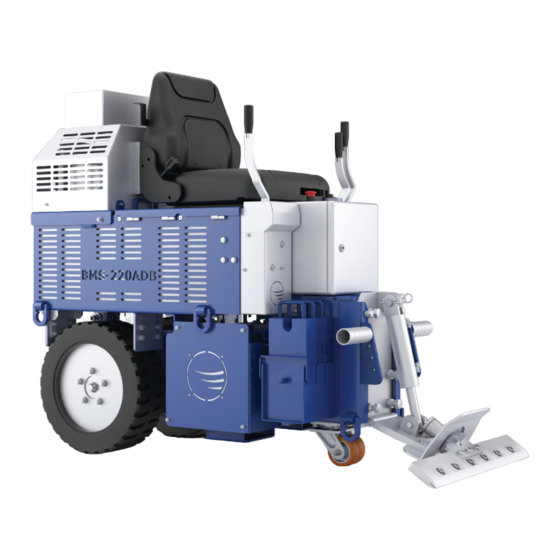
Only authorized and trained personnel may operate this machine. 2. Machine description The Blastrac BMS-220ADB ride-on stripper is ideally suited for medium and large sized applications with the added benefit of being battery operated for increased versatility. It is very maneuverable with zero turn radius, non-mark tires and complete hydraulic control. - Page 4 Tool holder Left wheel handle Blade holder 10 Tool position handle Electro box 11 Right wheel steer handle ON/Off key 12 Adjustable seat Battery discharge indicator/hour meter 13 Charger connection Emergency shut down 14 Oil filter Batteries set 15 Wheel scrapers Box with drive unit (motor with pumps)
-
Page 5: Safety
3. Safety It is important that all persons who are working with or maintaining this machine must read the manual carefully and understand it fully. Keep this manual always with the machine, to enable it to be referred to at any time Safety precautions Make sure that persons who are not operating the machine are not in the surrounding area of 5 meter ... - Page 6 Safety instructions Turn key to OFF and press Emergency shut down when changing the blade or during repairs on the machine. Turn key to OFF and press Emergency shut down when machine is parked. Park the machine always on a flat horizontal and levelled surface. Cover the sharp blade or remove it when park the machine.
- Page 7 Be aware of your surroundings and machine operating level. Do not side hill, do not run on steep incline, this could cause machine to tip over. Always drive backwards when driving up to a ramp or grade, and forwards when driving of the ramp. ...
-
Page 8: Initial Operation
4. Initial operation Before using the machine it is essential to inspect the machine every day. It is not permitted to use the machine if the machine safety is not according the checkpoints below. Checkpoints of electrical safety: Check if the power supply cable of the charger is unplugged and the cable is stored into the machine. ... -
Page 9: Operation
5. Operation During operating the BMP-4000, the following additional safety instructions must be followed closely. Switching on the machine Take place on the seat (4) and put foots on the footrests. Operating the machine is not possible because of the safety switch of the seat. Pull out the emergency switch (3). - Page 10 Driving the machine The drive of the machine is controlled by the two outside handles (1 and 3). Pushing both handles forwards, the machine drive forwards. Pulling both handles backwards, the machine drive backwards. The driving speed depends on the position of the handles. Pushing the right handle forwards the machine turns to the left. Pushing one handle forwards and pulling another handle backwards the machine will turns around its axis.
- Page 11 Controlling tool position cylinder The tool position cylinder is controlled by left inner handle. Push the handle to lower the tool and pull the handle to lift the tool to proper cutting angle. Continuing to push the handle will jack up the front of the machine.
-
Page 12: Battery Operation
Battery operation Machine is equipped with twelve batteries 4GBV 180 EV 8Volt, 180 Ah. Batteries do not take a memory allowing recharge at any state. Do not over discharge, this could cause damage to batteries. IMPORTANT Every service work on batteries should only be done by trained personnel. High amperage exist and can cause serious injury of death. - Page 13 Information about safety and maintenance form producer: Parameter which is important for batteries is the temperature in which they work. Optimum range is from -10⁰ C to 45⁰ C . Batteries may not be left in minimum temperature for long time. The low temperature can make the battery freezing what can damage them.
-
Page 14: Charger Operation
Charger operation The BMS-220 is equipped with a HF E 48-30 high frequency traction-battery charger. It is mounted on the back on machine to have a easy access. Turn the contact switch to ‘OFF’ when charging. Batteries will not charge when contact switch is in ‘ON’ position. - Page 15 Operator must be familiar with the control panel of the charger. The panel shows the status of charging of the batteries and a red light if there a fault occurs. On the picture below is shown charger system and panel. The charger starts and stops automatically when the contact switch is off and the plug is in.
-
Page 16: Maintenance
Store the cleaned and dry machine in a dry and humid free room. Protect the electrical motors from moisture, heat, dust and shocks. All repair work must to be done by qualified Blastrac personnel, this to guarantee a safe and reliable machine. Any guarantee on the machine is expired when: Non original Blastrac parts have been used ... -
Page 17: Hydraulic System Instruction
Hydraulic system instruction To check oil level on the side of tank is installed indicator. Level should be half the glass of the level indicator. If you don’t see the oil in the indicator, the level is too low. If the level is above the glass, the level is too high. Next to the it is mounted plug which close the hole by which oil can be refill. - Page 18 Drain plug Oil filter For all standard job with hydraulic system like: Hose Pump Motor Valve Filter Cylinder Before doing any maintenance disconnect power and block machine in stable position. Because most of fittings in machine is O-ring style it is important is to know how to solve O-ring leaks. Fittings should be tighten with proper wrench size.
- Page 19 Cutting head & blades Weight vs. sharpness The most common way to compensate for a dull blade is to add more weight and raise the blade angle (see re- scrape setting). Weight allows dull blades to be used to a point. Weight also causes blades to dull and break easier.
- Page 20 1) Tool – depending of the needs 2) Tool holder – lower part 3) Tool holder – upper part 4) Tool holder 5) Debris deflector – new holder shape 6) Universal lower cutting head support Cutting head insertion With machine off, insert desired cutting head into cutting head holder. Secure with cutting head clip. Shank blade insertion Shank blades do not require a cutting head.
- Page 21 M20 bolt with securing nut M12 bolt with securing bolt Slide plate...
-
Page 22: Blades Application
7. Blades application Efficient and fast work can be reached by using correct blades and settings. Operator must remember to prepare correct angle and also keep blade sharp. During work blade start to be dull. To reduce this process operator can add extra weight or change angle to the ground. But that action make blades more potential to brake. - Page 23 Wood Floor On the concrete beveled must be face upwards: Concrete Floor Working place should be keep clean. When some part of material is removed before second run always is better to make floor clean. Debris and dirt can make blade dull really quick. Dull blades can be sharpening by using electric grinder with disc 120 grit of finer.
- Page 24 Wings It’s important to keep the “wings” sharp. They can be sharpening by the same way like other blades. Sometimes it happened that job need be made quite quick. To save time on jobsite good to have many tools and only replace them. All service ( sharpening ) can be done in that case on workshop. Cutting heads are use to mount blades.
- Page 25 Top part with bottom are screw together by M10 bolts. The cutout on lower plate ensures a accurate and reliable fixation of the tool. Types of blades For different materials need to be mounted special tools. The shape and width are define by many years of experience.
- Page 26 Using correct blades is a only half of success. Second is put tool in optimal geometry to the ground. Information to the most popular materials: VCT tiles : slide plate with distance between 6 to 12mm from floor. It’s better to start with narrow cutting head.
- Page 27 Ditching Cross room ditching Ditch 50 Tile 300 To 155mm To 600mm Run the machine the same direction that the ditches are made When removing hard to remove ceramic, Vct or vat, cross-room ditching will help to make the removal easier. Using a blade 50 to 155mm in width, make ditches 300 to 600mm apart in the same direction the machine will be removing the goods.
- Page 28 Checker board ditching Ditch should be wide As much is possible Carpet wide from 1200 to 1800mm Run the machine crossways from the directions that the ditches are To make carpet removal and debris cleanup easier, checker board ditching is very helpful. Using as wide of a self-scoring blade as possible, make ditches apart crossways from the way the machine will be removing the goods.
-
Page 29: Technical Data
Hardwood parquet / ceramics / linoleum / vinyl / carpet / Application adhesives / glue / tiles etc… 1550 mm Length 685 mm Width 1350 mm Height 960/1080 kg Weight Design and specifications are subject to change without notice by Blastrac USA... - Page 30 Contact Blastrac NA 13201 North Santa Fe Avenue Oklahoma City, OK 73114 Tel: 800-256-3440 Fax: 405-478-8608 www.blastrac.com...
- Page 31 13201 North Santa Fe Avenue Oklahoma City, OK 73114 Ph: 800-256-3440 F: 405-478-8608 blastrac.com Product Warranty Standard Equipment Products: Blastrac warrants its Blastrac Standard Equipment Products against defects in quality of material and workmanship, under normal and proper use for a period of 1 Year from the date of delivery, as noted on the returned warranty registration card, or, in the case of Rental Fleet Machines, 180 Days from the date of assignment to Rental Fleet.
- Page 32 Blastrac Returned Merchandise Authorization (RMA) Form. Blastrac will then send the RMA form to the customer authorizing the return of the parts for warranty evaluation. The parts must be received within sixty (60) days following the RMA origination date or the warranty claim will be denied.
- Page 33 ® the information recorded here by registering online at blastrac.com, or complete this page and fax to 866-485-1046, or if you prefer, detach and mail to: Blastrac, 13201 North Santa Fe Avenue, Oklahoma City, OK 73114-9901...
Need help?
Do you have a question about the BMS-220 ADB and is the answer not in the manual?
Questions and answers