
Related Manuals for Blastrac BMS-H2750


Summary of Contents for Blastrac BMS-H2750
- Page 1 MODEL BMS-H2750 Floor Scraping System HIGH VOLUME RIDE-ON SCRAPER Trust the Original Surface Preparation Experts blastrac.com 800.256.3440...
- Page 2 TABLE OF CONTENTS BMS-H2750 HURRICANE SECTION I GENERAL DESCRIPTION SECTION II SPECIFICATIONS SECTION III SAFETY AND PRECAUTIONS SECTION IV INSTRUMENTS AND CONTROLS SECTION V START-UP AND BREAK-IN SECTION VI MACHINE OPERATION SECTION VII PREVENTIVE MAINTAINANCE SECTION VIII ENGINE SECTION IX FRAME &...
- Page 3 OPERATIONS MAINTENANCE MANUAL CUSTOMER SERIAL NUMBER DATE SHIPPED...
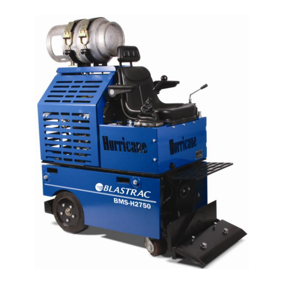
- Page 4 SECTION I GENERAL DESCRIPTION BMS-H2750 The BMS-H2750 is operated by a propane-powered engine, driving a tandem hydrostatic pump system, creating a (skid-steer) zero turn radius drive train. Surface covering and coatings are removed by lowering a weighted blade onto the surface and moving forward under a high torque drive system. The...
- Page 5 SECTION II SPECIFICATIONS Weight 2750 lbs Removable weight 1000 lbs Height with Propane Tank 58 inches Width 25 inches Length with blade 51 inches Length without blade 41 inches Engine 25 Hp Kohler Max Ground Speed 440 ft per min. Torque per Wheel 1000 ft.
- Page 6 SAFETY WARNING CARBON MONOXIDE can cause severe nausea, fainting or death. Do not operate engine in closed or confined area without proper ventilation.
- Page 7 Wear proper eye and ear protection and heavy duty work gloves at all times. Practice good Preventive Maintenance. Practice good housekeeping. Allow the BMS-H2750 to come to a complete stop, turn off engine, and chock rear wheels before performing any maintenance procedures. Replace worn parts when necessary.
- Page 8 The BMS-H2750 is not a toy. All operators must be over 18 years of age and must have read and reviewed the safety and procedures manual before operating the machinery. The BMS-H2750 is designed for surface preparation ONLY. It is not intended for towing, pushing or any other procedure not described in this manual.
- Page 9 SECTION IV Instruments and Controls View # 1 Top view of BMS-H2750 machine View # 2 Left side view of BMS-H2750 machine View #3 Right side view of BMS-H2750 machine View #4 Front view of BMS-H2750 machine...
- Page 10 View #1 Top View...
- Page 11 VIEW #2 LEFT SIDE DETAIL TANK MOUNT FC-022 PROPANE FULE TANK FC-021 SEAT FC-015 STEERING CONTROL JOY STICK VALVE HUH-042 THROTTLE HFC-039 FOOTSTEP HFC-035 SIDE COWLING LATCHES FC-048 BLADE BAR BOLTS FC-008 LUG BOLTS FC-002 CASTERS FC-005 REAR TIRES FC-001...
- Page 12 VIEW #3 RIGHT SIDE DETAIL PROPANE QUICK COUPLING PROPANE FUEL TANK FC-021 PROPANE TANK MOUNT FC-022 STEERING CONTROL SIDE COWLING LATCHES FC-048 LUG BOLTS FC-002 CASTER FC-005...
- Page 13 BMS-H2750 START-UP AND BREAK-IN The BMS-H2750 has been safety tested and run at our factory prior to shipping. All fluid levels have been topped off; however, no propane has been added to the tanks for safety shipment purposes. Before running the BMS-H2750 please check the following items that may have shifted or changed during shipping.
- Page 14 3 diagrams depicting the TOP, LEFT, and RIGHT views of machine. These drawings show the activation of all moving parts of the BMS-H2750. 1. To move the machine: Using the right hand, slowly move the shifter lever in the desired direction.
- Page 15 scraping will negatively affect scraper productivity and steering. Do not transport machine with front of machine off the surface of floor higher than 1/2" or irreparable damage to lift cylinders will result. Illustration of correct scraping procedures...
- Page 17 SECTION VII Preventative Maintenance OLLOW OHLER SUGGESTED SCHEDULE FOR ENGINE MAINTAINANCE DAILY MAINTENANCE CHECK HYDRAULIC OIL INSPECT FOR HYDRAULIC OIL LEAKS INSPECT FOR PROPANE SYSTEM LEAKS SERVICE ENGINE AIR CLEANER RETORQUE WHEEL LUG BOLTS 100 HR MAINTENANCE GREASE CASTER BEARINGS INSPECT ALL BOLTS AND NUTS AND TIGHTEN IF NEEDED 400 HR MAINTAINANCE...
- Page 18 SECTION VIII ENGINE COMPONENTS LIST DESCRIPTION PART NUMBER 1 ENGINE HUE-001 Throttle Linkage Assembly HUE-005 Flywheel Fan HUE-006 9 ENGINE MOUNT BOLTS HUE-009 10 ENGINE AIR CLEANER HUE-010 11 ENGINE AIR PRE-CLEANER HUE-011 12 ENGINE OIL FILTER HUE-012 13 ENGINE SPARK PLUGS HUE-013 14 OIL DRAIN HOSE ASSEMBLY HUE-014...
- Page 19 Hydrostatic relief valve HUE-045 Muffler brace HUE-047 Muffler heat shield (upper) HUE-060 Muffler heat shield (lower) HUE-061 Engine drive pulley HUE-062 Engine drive pulley bushing HUE-063 Pump drive pulley HUE-064 Pump drive pulley bushing HUE-065 SECTION IX FRAME AND COWLINGS KEY DESCRIPTION PART NUMBER 1.
- Page 20 29. THROTTLE CABLE HFC-039 30. CASTER WHEEL ONLY FC-040 31. OIL COOLER MOUNT HFC-041 32. IGNITION KEYS FC-042 33. WHEEL MOTOR NUT FC-045 34. WHEEL MOTOR KEY FC-046 35. SIDE COWLING LATCHES FC-048 36. BATTERY HFC-063 37. TACHOMETER HFC-070 38. SHADING STRIP HFC-071 39.
- Page 21 SECTION X Hydraulic components parts list DESCRIPTION PART NUMBER GEAR PUMP HUH-001 JOYSTICK VALVE HUH-042 LIFT CYLINDER HUH-041 CASTER HFC-005 TILT CYLINDER HUH-010 RETURN HOSE HUH-020 PUMP PRESSURE HOSE HUH-002 SUCTION HOSE HUH-021 HUH-004 UPPER LIFT CYLINDER HOSE HUH-003 LOWER LIFT CYLINDER HOSE HUH-022 LIFT CYLINDER SUPPLY HOSE HUH-023...
- Page 22 Hydraulic Components Illustration return to tank Fittings side of valve...
- Page 23 SECTION X Hydrostat components parts list DESCRIPTION PART NUMBER FILTER HEAD HUH-043 FILTER ELEMENT HUH-044 TANK HUH-045 HYDROSTAT ASSEMBLY HUH-046 WHEEL MOTOR HUH-047 FILLER CAP HUH-048 WHEEL MOTOR HOSE HUH-049 ½” PUSH LOC HUH-050 ½” PUSH LOC HUH-050 ½” PUSH LOC HUH-050 ½”...
- Page 24 Hydrostat Components Illustration FILTER HEAD 25 MICRON SUCTION FILTER RIGHT LEFT...
- Page 25 SECTION XIII STEERING JOYSTICK ASSEMBLY AND CABLES DESCRIPTION PART NUMBER BALL KNOB HSJ-001 HANDLE HSJ-002 BOOT HSJ-003 FORK ASSEMBLY HSJ-004 4-WAY PIVOT HSJ-005 ¼”-28 ROD END HSJ-006 ¼”-28 ROD END W/STUD HSJ-007 CONTROL CABLE LEFT HSJ-010 CONTROL CABLE RIGHT HSJ-011 CABLE MOUNT REAR HSJ-012 CABLE MOUNT FRONT...
- Page 26 13201 North Santa Fe Avenue Oklahoma City, OK 73114 Ph: 800-256-3440 F: 405-478-8608 blastrac.com Product Warranty Standard Equipment Products: Blastrac warrants its Blastrac Standard Equipment Products against defects in quality of material and workmanship, under normal and proper use for a period of 1 Year from the date of delivery, as noted on the returned warranty registration card, or, in the case of Rental Fleet Machines, 180 Days from the date of assignment to Rental Fleet.
- Page 27 Blastrac Returned Merchandise Authorization (RMA) Form. Blastrac will then send the RMA form to the customer authorizing the return of the parts for warranty evaluation. The parts must be received within sixty (60) days following the RMA origination date or the warranty claim will be denied.
- Page 28 ® the information recorded here by registering online at blastrac.com, or complete this page and fax to 866-485-1046, or if you prefer, detach and mail to: Blastrac, 13201 North Santa Fe Avenue, Oklahoma City, OK 73114-9901...
Need help?
Do you have a question about the BMS-H2750 and is the answer not in the manual?
Questions and answers