Table of Contents
Advertisement
Quick Links
ISO Registered Company
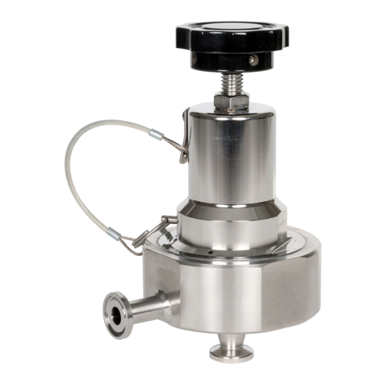
PRESSURE REDUCING SANITARY REGULATORS
I. DESCRIPTION AND SCOPE
Models PA1 and PL1 are pressure reducing regulators used to control downstream (outlet or P
outlet size 1/2" (DN15) and 3/4" (DN 20) with Tri-Clamp
stainless steel construction. Refer to Tech ni cal Bulletin PA1/PL1-TB for specific design conditions and selection
recommendations.
II. INSTALLATION
Installation of adequate overpressure pro tec tion
is recommended to pro tect the reg u la tor and
all downstream equip ment from dam age in the
event of reg u la tor failure.
1. An inlet block valve should al ways be installed
upstream of the regulator.
2. If service application is continuous such that
shut down is not readily accomplished, it is rec-
ommended that an inlet block valve, outlet block
valve, and a manual bypass valve be installed.
The maximum outlet pressure is list ed on the
name plate as the upper range spring pres sure
level, and is the rec om mend ed "upper operative
limit" for the sens ing diaphragm (see Sec tion IV.
Startup, Step 7). Higher press ures could dam age
the di a phragm. (Field hydro static tests fre quent ly
destroy dia phragms. DO NOT HYDRO STATIC TEST
THROUGH AN IN STALLED UNIT; ISO LATE FROM
TEST.)
INSTALLATION, OPERATION & MAINTENANCE MANUAL (IOM)
MODELS PA1 & PL1
CAUTION
CAUTION
SECTION I
connections. Each model incorporates electro-polished
®
SECTION II
Supply
@ P
1
Recommended Piping Schematic
For Pressure Reducing Station
Blowdown-Drain
3. An outlet pressure gauge should be located
ap proxi mately ten pipe diameters downstream, and
with in sight.
4. All installations should include a downstream re lief
device if the inlet pressure could exceed the pres sure
rating of any downstream equip ment or the maximum
outlet pressure rating of the unit.
5. Flow Direction: Install so the flow direction match es
the arrow stamped on the regulator body.
6. Install unit with spring chamber (2) in the vertical
position to allow for proper draining.
IOM-PA1-PL1
) pressure. Inlet and
2
SRV
Bypass
Model
PL1
Blowdown-Drain
05-17
Outlet
@ P
2
P
1
Advertisement
Table of Contents

Related Manuals for cashco PA1


Summary of Contents for cashco PA1
- Page 1 ) pressure. Inlet and outlet size 1/2" (DN15) and 3/4" (DN 20) with Tri-Clamp connections. Each model incorporates electro-polished ® stainless steel construction. Refer to Tech ni cal Bulletin PA1/PL1-TB for specific design conditions and selection recommendations. SECTION II II. INSTALLATION...
-
Page 2: Principle Of Operation
SECTION IV IV. STARTUP 7. Continue to slowly open the inlet (upstream) 1. For Model PA1: ensure that lock-open pin (19) is block valve until fully open. not inserted into the hole in the side of the spring chamber. See Sec tion VII. -
Page 3: Maintenance
Not rotate the plug. See Figure 1. Remove first through the body cap opening for Model pressure plate (14). NOTE: For Model PA1: PL1 or through inlet port for Model PA1. when nut is removed the plug (10) may slide out through the bottom, inlet connection. Do 14. - Page 4 24. Release all pressure that was applied to inlet large body opening faces upward. For Model of the regulator. PA1: hold on to threaded end of plug so it does not fall out of the inlet, bottom connection. 25. Place the range spring (8) on top of the pressure plate.
- Page 5 SECTION VII VII. CLEANING PROCEDURE for MODEL PA1: A. Pre-Sanitation: CAUTION 1. Owner should refer to owner’s op er at ing Owner’s cleaning solution must be com pat i ble with pro ce dures for system shutdown to include regulator’s trim materials.
-
Page 6: Troubleshooting Guide
C. Install safety relief valve, or rupture disc. Restricted diaphragm movement. D. Assure no moisture in spring chamber at temperatures below freeze point. Assure no dust or debris entering vent opening. If rainwater or debris can enter, re-orient regulator. IOM-PA1-PL1... -
Page 7: New Replacement Unit
Cashco, Inc. does not assume responsibility for the selection, use or maintenance of any product. Responsibility for proper selection, use and maintenance of any Cashco, Inc. - Page 8 FIGURE 2: Basic Model PA1 - showing Metal Seat Lanyard Drive Screw location Model PA1 ONLY. Insert lock open pin here for CIP and SIP Feature, Model PA1 ONLY. FIGURE 3: Basic Model PL1 - showing Soft Seat Item No.
- Page 9 ATEX requires that all components and equipment be evaluated. Cashco pressure regulators are considered components. Based on the ATEX Directive, Cashco considers the location where the pressure regulators are installed to be classified Equipment-group II, Category 3 because flammable gases would only be present for a short period of time in the event of a leak.
- Page 10 If the above issues are addressed by selecting options that do not have potential sources of ignition, avoiding options that have not been assessed, and by taking the proper usage issue precautions, then Cashco regulators can be considered to be a mechanical device that does not have its own source of ignition and thus falls outside the scope of the ATEX directive.
Need help?
Do you have a question about the PA1 and is the answer not in the manual?
Questions and answers