Table of Contents
Advertisement
Quick Links
Magistro
Magistro
Z-wave nOde fOR shutteRs
quick guide
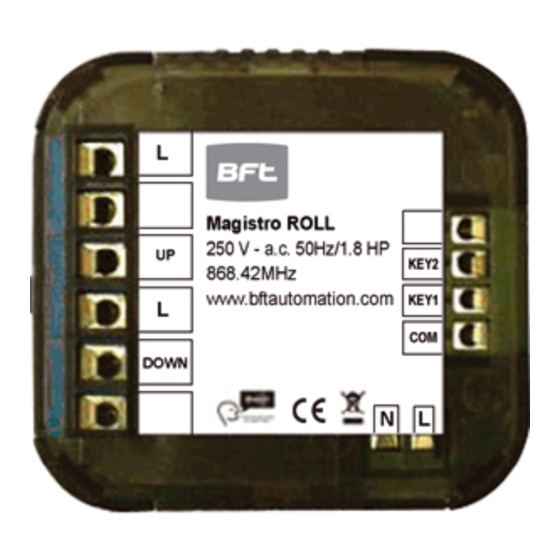
terminal Block
Push Button
indicator Light
Technical specs
normal operating voltage
Maximum load
frequency range
wireless Range
Basic Operations
-
the Magistro ROLL can be remotely controlled.
-
the Magistro ROLL can be add/remove from the network by pressing the push
button on the front of the device, or by external switch
-
the Magistro ROLL's indicator light will indicate the status of the
Magistro ROLL.
Mounting
1. turn Off power by switching off the circuit breaker or removing the fuse and
test that power is off before wiring!
ROLL
ROLL
250v ~ a.c. 50hz
1.8 hP
868.42Mhz
up to 30m line of sight
PaRaMteR: 1
siZe: 1
vaLues: 2
twO tOggLe switch
uP
shutteR
dOwn
Magistro ROLL
connect with 2 gang Push Button switch
2. ensure Magistro ROLL capacity matches the load requirements.
3. wall installation: connect it with your existing external switch, default is
two buttons with neutral position switch. Please see below wiring diagrams
& configuration Parameters.
4. Reapply power to the circuit at fuse box or circuit breaker to test the system
carefully, if the indicator light on Magistro ROLL blinks 30 seconds and then keep
breathing, it means the installation is in good condition.
5. turn Off the power again.
6. for wall installation: insert your external switch together with Magistro ROLL into
switch box being careful not to pinch or crush wires, and secure it with screws.
Reapply power to the circuit at fuse box or circuit breaker.
Maximum load:
250v ~ a.c. 50hz , 1.8hP
wall installation wiring diagram, connect with external switch: (see figure B)
Please note: a 6a external fuse before the red wire live of the Magistro ROll
switch must be installed in the installation for protect the Magistro ROLL switch
Push
Push
ButtOn
ButtOn
switch
switch
(uP)
(dOwn)
L
n
Advertisement
Table of Contents

Related Manuals for BFT Magistro ROLL


Summary of Contents for BFT Magistro ROLL
- Page 1 (see figure B) 1. turn Off power by switching off the circuit breaker or removing the fuse and Please note: a 6a external fuse before the red wire live of the Magistro ROll test that power is off before wiring!
- Page 2 Wide inclusion in the network. this way the range of the Z-wave network can be expanded to when the Magistro ROLL is not yet included in a Z-wave network, nwi will be 150 meters indoors (limit of 4 hops).
- Page 3 Magistro ROLL is completely wiring. paRaMTeR q: i can’t have my Magistro ROLL included into my Z-wave network, what am i doing size 1 Default 0...
Need help?
Do you have a question about the Magistro ROLL and is the answer not in the manual?
Questions and answers