
Related Manuals for Emerson Rosemount 225


Summary of Contents for Emerson Rosemount 225
- Page 1 Reference Manual 00809-0100-3225, Rev AA August 2018 ™ Rosemount Toroidal Conductivity Sensors...
- Page 3 Safety Information WARNING HIGH PRESSURE AND TEMPERATURE HAZARD Before removing the senosr, reduce the process pressure to 0 psig and cool down the process temperature. Failure to reduce the pressure and temperature may cause serious injury to personnel. CAUTION EQUIPMENT DAMAGE The wetted sensor materials may not be compatible with process composition and operating conditions.
-
Page 5: Table Of Contents
3.4 Calibrating against a Referee - Grab Sample .................. 22 Chapter 4 Troubleshooting ......................25 4.1 Maintaining the sensor ........................25 4.2 Troubleshooting ........................... 25 Chapter 5 Accessories ......................... 29 Chapter 6 Return of Materials ..................... 31 Rosemount 225 Sensors... - Page 6 Contents Reference Manual August 2018 00809-0100-3225 Reference Manual...
-
Page 7: Description And Specifications
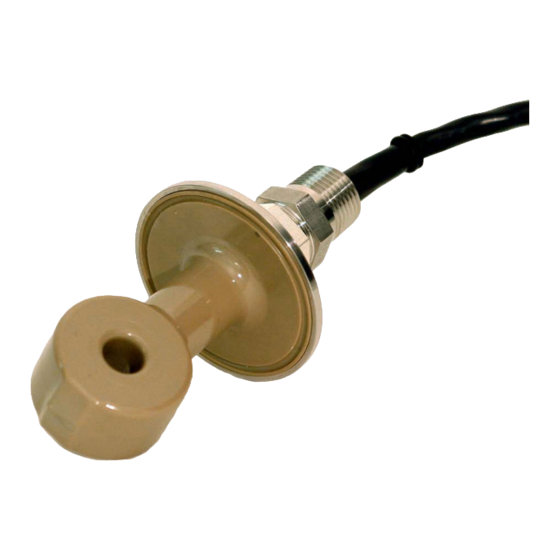
Description and specifications General Rosemount 225 toroidal conductivity sensors are intended to be used in many pharmaceutical and food and beverage applications where a sanitary design is required. These corrosion and fouling resistant sensors are ideal for measuring the concentration of CIP solutions, detecting product/water interfaces, checking product quality, and monitoring eleuents in chromatographic separations. -
Page 8: Specifications
21CFR177.2415 and 3A standard 74-06) Unfilled PEEK (meets USP VI standards) Unfilled Tefzel 230 °F (110 °C) Table 1-3: Rosemount 225 Sanitary Toroidal Conductivity Sensor Ordering Information Model Sensor Type Toroidal Conductivity Sensor Body Material & Mounting Type Glass-filled PEEK with tri-clamp... - Page 9 Reference Manual Description and specifications 00809-0100-3225 August 2018 Table 1-3: Rosemount 225 Sanitary Toroidal Conductivity Sensor Ordering Information (continued) Transmitter Compatibility Standard integral cable Integral cable with additional shielding for improved EMI/RFI protection Typical model number: 225-03-56 Only available with -56 option.
- Page 10 Description and specifications Reference Manual August 2018 00809-0100-3225 Reference Manual...
-
Page 11: Chapter 2 Install
Keep at least 1 in. (25 cm) between the sensor and the pipe wall. If clearance is too small, calibrate the sensor in place. Ensure that the sensor is completely submerged in liquid. Figure 2-1: Rosemount 225 dimensional drawing Procedure 1. Mount the sensor in the pipe. -
Page 12: Wiring The Sensor
Install Reference Manual August 2018 00809-0100-3225 Wiring the Sensor Keep sensor wiring away from ac conductors and high current demanding equipment. Do not cut the cable. NOTICE For additional wiring information on this product, please refer to the Liquid Transmitter Wiring Diagrams. - Page 13 Reference Manual Install 00809-0100-3225 August 2018 Figure 2-3: Wiring diagram for Rosemount 1056 and 56 Transmitters Rosemount 225 Sensors...
- Page 14 Install Reference Manual August 2018 00809-0100-3225 Figure 2-4: Wiring diagram for Rosemount 1066 Transmitters Reference Manual...
- Page 15 Reference Manual Install 00809-0100-3225 August 2018 Rosemount 225 Sensors...
- Page 16 Install Reference Manual August 2018 00809-0100-3225 Figure 2-5: Wiring diagram for Rosemount 5081 Transmitters Reference Manual...
- Page 17 Wire sensors point to point. For wiring at the transmitter end, refer to the appropriate transmitter wiring diagram. For interconnecting cable 23294-00, use the 225-54 wiring diagram. For interconnecting cable 23294-04 and 23294-05, use the 225-54 wiring diagram. Figure 2-7: Remote Junction Box (PN 23550-00) dimensions Rosemount 225 Sensors...
- Page 18 Install Reference Manual August 2018 00809-0100-3225 Reference Manual...
-
Page 19: Chapter 3 Calibration
Calibration Sensor calibration The nominal cell constant of the Rosemount 225 sensor is 2.7/cm. The error in cell constant is about ±10%, so conductivity readings made the using the nominal cell constant will have an error of at least ±10%. Wall effects,as shown in... - Page 20 Calibration Reference Manual August 2018 00809-0100-3225 Procedure 1. Remove the sensor from the pipe. 2. Fill a container with the standard solution. If wall effects are absent in the process installation, use a sufficiently large container for calibration to ensure that wall effects are absent. To check for wall effects, fill the container with solution and place the sensor in the center, submerged at least 3/4 of the way up the stem.
-
Page 21: Calibrating Against A Referee - In-Process
Tap and hold the flow cell in different positions to allow bubbles to escape. Wait for readings to stabilize before starting the calibration. 3. Adjust the process sensor to match the conductivity measured by the referee instrument. Rosemount 225 Sensors... -
Page 22: Calibrating Against A Referee - Grab Sample
Calibration Reference Manual August 2018 00809-0100-3225 Results Figure 3-4 shows the arrangement. Figure 3-4: Calibration with a referee instrument example Calibrating against a Referee - Grab Sample This method is useful when calibration against a standard is impractical or when in-process calibration is not feasible, because the sample is hot, corrosive, or dirty, making handling the waste stream from the referee sensor difficult. - Page 23 August 2018 3. Place the sensors in the grab sample. Wait until the readings are stable before starting the calibration. 4. Adjust the reading from the process analyzer to match the conductivity measured by the referee sensor. Rosemount 225 Sensors...
- Page 24 Calibration Reference Manual August 2018 00809-0100-3225 Reference Manual...
-
Page 25: Chapter 4 Troubleshooting
Cell constant is wrong. Wall effects are Calibrate the sensor in place in the present. process piping. See Calibration. Wrong temperature correction Check that the temperature correction algorithm is being used. is appropriate for the sample. See transmitter manual for more information. Rosemount 225 Sensors... - Page 26 Troubleshooting Reference Manual August 2018 00809-0100-3225 Table 4-1: Troubleshooting (continued) Problem Probable cause Solution Temperature reading is inaccurate. Disconnect the RTD leads (Figure 4-1) and measure the resistance between the in and common leads. Resistance should be close to the value in Table 4-2.
- Page 27 Reference Manual Troubleshooting 00809-0100-3225 August 2018 Figure 4-1: Resistance check. Disconnect leads from transmitter before measuring resistances. Rosemount 225 Sensors...
- Page 28 Troubleshooting Reference Manual August 2018 00809-0100-3225 Reference Manual...
-
Page 29: Chapter 5 Accessories
Remote junction box without preamplifier 23294-00 Interconnecting extension cable, unshielded, prepped (for use with remote junction box) 23294-05 Interconnecting extension cable, shielded, prepped (for use with remote junction box) 9200276 Interconnecting extension cable, shielded, unprepped (for use with remote junction box) Rosemount 225 Sensors... - Page 30 Accessories Reference Manual August 2018 00809-0100-3225 Reference Manual...
-
Page 31: Return Of Materials
Return of Materials 00809-0100-3225 August 2018 Return of Materials For repair and warranty inquiries, please contact Rosemount Customer Care to obtain a Return Material Authorization (RMA) number. Drain the sensor of fluids before shipping it back to Rosemount. Rosemount 225 Sensors... - Page 32 The Emerson logo is a trademark and service mark of Emerson Electric Co. Rosemount is a twitter.com/rosemount_news mark of one of the Emerson family of companies. All other marks are the property of their Facebook.com/Rosemount respective owners. The contents of this publication are presented for information youtube.com/RosemountMeasurement...
Need help?
Do you have a question about the Rosemount 225 and is the answer not in the manual?
Questions and answers