Table of Contents
Advertisement
Quick Links
Instruction Manual
Form 5729
March 2005
Type 249W Cageless Wafer Style Level Sensor
Contents
. . . . . . . . . . . . . . . . . . . . . . . . . . . . . . .
. . . . . . . . . . . . . . . . . . . . . . . . .
. . . . . . . . . . . . . . . . . . . . . . . . . . . . . .
. . . . . . . . . . . . . . . . . . . . . . . . . . . . . . . .
. . . . . . . . . . . . . . . . . . . . . . . . . . . . . .
. . . . . . . . . . . . . . . . . . . . . . . . . . . .
. . . . . . . . . . . . . . . . . . . . . . . . . . . . . . . .
Introduction
Scope of Manual
This instruction manual includes maintenance, and
parts ordering information for the Type 249W
cageless wafer style sensor.
Although the sensor is usually shipped with attached
controller or transmitter, as shown in figure 1, this
manual does not include operation, installation,
calibration, maintenance, and parts ordering
information for the controller/transmitter or for the
complete unit. For this information, refer to the
appropriate controller/ transmitter instruction manual.
www.Fisher.com
. . . . . . . . . . . . . . . . . . . . . .
. . . . . . . . . . . . . . . . . .
. . . . . . . . . . . . . . .
. . . . . . . . . . . . . . . . . . . . . .
. . . . . . . . . . . . . . .
. . . . . . . . . .
. . . .
10
. . . . . . . . . . . . . . .
11
. . . . . . . . . . . . . . . .
12
13
. . . . . . . .
13
14
1
1
2
2
3
3
3
3
5
8
9
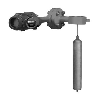
W8231 / IL
Figure 1. Type 249W Sensor with DLC3000 Series
No person may install, operate, or maintain a Type
249W sensor and the attached controller or
transmitter without first D being fully trained and
qualified in valve, actuator, and accessory
installation, operation and maintenance, and D
carefully reading and understanding the contents of
this manual. If you have any questions concerning
these instructions, contact your Fisher sales office
before proceeding.
Neither Emerson, Emerson Process
Management, nor Fisher assume
responsibility for the selection, use, or
maintenance of any product.
Responsibility for the selection, use,
and maintenance of any Fisher
product remains with the purchaser
and end-user.
249W Level Sensor
Digital Level Controller
Note
Advertisement
Table of Contents

Related Manuals for Emerson Fisher 249W


Summary of Contents for Emerson Fisher 249W
-
Page 1: Table Of Contents
This instruction manual includes maintenance, and parts ordering information for the Type 249W Note cageless wafer style sensor. Neither Emerson, Emerson Process Although the sensor is usually shipped with attached Management, nor Fisher assume controller or transmitter, as shown in figure 1, this... -
Page 2: Description
The torque tube assembly contact: consists of a hollow torque tube with a shaft welded inside it at one end and protruding from it at the Emerson Process Management other end. Educational Services, Registration P.O. Box 190; 301 S. 1st Ave. -
Page 3: Type Number Description
Instruction Manual Form 5729 249W Level Sensor March 2005 Type Number Description TYPE 249W WAFER BODY D Type 249W—3- or 4-inch, ANSI Class 150, 300, 600 steel cageless sensor. 3- OR 4 - INCH RF FLANGE The Parts List section shows some Type 249W constructions, standard displacer lengths, and standard materials. - Page 4 Instruction Manual Form 5729 249W Level Sensor March 2005 W8324 W8267 / IL CAGE WITH SIDE CONNECTIONS CAGE WITH TOP AND BOTTOM CONNECTIONS Figure 5. Type 249W Sensor Cage-Mounted on Side of Vessel FLANGE ADAPTOR (REQUIRED IF FLANGE ADAPTOR (REQUIRED FLANGE CONNECTIONS ARE OTHER IF FLANGE CONNECTIONS ARE THAN 3-INCH)
-
Page 5: Mounting The Sensor On The Process
Instruction Manual Form 5729 249W Level Sensor March 2005 VENT VENT 3- OR 4-INCH CLASS 150, 300, 3- OR 4-INCH CLASS 150, 300, CONNECTION CONNECTION OR 600 BLIND FLANGE OR 600 BLIND FLANGE (2.87) (2.87) 3- OR 4-INCH CLASS 150, 300, 3- OR 4-INCH CLASS 150, 300, OR 600 FLANGE OR 600 FLANGE... - Page 6 Instruction Manual Form 5729 249W Level Sensor March 2005 LEFT RIGHT HAND HAND MOUNT MOUNT 8.04 8.04 19.73 19.75 SIZE Inch 5.00 6.19 24.00 2.87 HEAT INSULATOR EXTENSION 2.87 2.34 5.49 2.34 2.61 1/2 - 14 NPT 2 PLACES END VIEW OF INSTRUMENT 10C0786-B NOTE: DIMENSIONS D, F, AND G ARE CUSTOMER SPECIFIED DIMENSIONS...
- Page 7 Instruction Manual Form 5729 249W Level Sensor March 2005 Table 1. Recommended Bolt Torque for Typical Lubricants (3-Inch Flanges) Lubricant Fisher NCF2 Bolt and Nut Mating Flange Bolt Size Molykote 321R Lubriplate Mag - 1 Nickel Never-Seez Coating Material Material Class Class Torque, NSm (lbfSft)
-
Page 8: Maintenance
Instruction Manual Form 5729 249W Level Sensor March 2005 WARNING Always wear protective clothing and eyewear when performing any maintenance operations to avoid personal injury. Avoid personal injury or property damage resulting from the sudden release of pressure. Before performing any maintenance procedure: D Relieve any process pressure in the process vessel where the Type... -
Page 9: Removing The Displacer And Stem
Instruction Manual Form 5729 249W Level Sensor March 2005 W8227 W8225 Figure 13. Blind Flange Installation Figure 14. Type 249W Installation Complete or liquid, it may hold pressure or hazardous liquid for Handle the displacer with care. an extended period. Consider the characteristics of the specific process liquid in use. -
Page 10: Replacing The Displacer, Cotter Spring, Stem End Piece, And Displacer Spud
Instruction Manual Form 5729 249W Level Sensor March 2005 and be lifted out with the sensor body. CAUTION If separating the displacer and displacer rod, remove the cotter spring (key 10). If the displacer is to be disconnected from the displacer rod before being removed from the process vessel or displacer cage, provide a suitable CAUTION... -
Page 11: Replacing The Torque Tube
Instruction Manual Form 5729 249W Level Sensor March 2005 provide a suitable means of 2. Remove the controller/transmitter and displacer supporting the displacer to prevent it (key 4). Then, remove the hex nuts (key 20) that from dropping into the vessel or cage hold the torque tube arm (key 2) to the wafer body and being damaged. -
Page 12: Replacing The Torque Tube Arm And Changing The Mounting
Instruction Manual Form 5729 249W Level Sensor March 2005 DISPLACER ROD ASSEMBLY ROTARY SHAFT TORQUE TUBE OUTER TUBE END POSITIONING PLATE DRIER BEARING W0145-1*/IL W0654-1/IL REMOVAL OR INSTALLATION OF POSITIONING PLATE EXPLODED VIEW OF TORQUE TUBE AND DISPLACER ROD ASSEMBLY Figure 15. -
Page 13: Parts Ordering
Use only genuine Fisher replacement Note parts. Components that are not supplied by Fisher should not, under Neither Emerson, Emerson Process any circumstance be used in any Management, nor Fisher assume Fisher instrument. Use of components responsibility for the selection, use, or not supplied by Fisher will void your maintenance of any product. -
Page 14: Parts List
Instruction Manual Form 5729 249W Level Sensor March 2005 PARTS NOT SHOWN 23 19B3127 Figure 16. Type 249W Sensor Construction Parts List Description Part Number Torque Tube Assy Std wall Description Part Number N05500 (std w/WCC steel) 1K4493X0012 Wafer Body 316 SST (std w/CF8M) 1K4503000A2 3-Inch... - Page 15 Instruction Manual Form 5729 249W Level Sensor March 2005 Description Part Number Description Part Number Displacer Displacer(1) (cont’d) 2-3/8 x 14 inches (62 cubic inches) 1-1/8 x 96 inches (95 cubic inches) 3.75 pounds (1400 psi) 4.75 pounds S30400 15A4547X042 S30400 (1570 psi) 15A5102X042 S31600...
- Page 16 Fisher is a mark owned by Fisher Controls International LLC, a member of the Emerson Process Management business division of Emerson Electric Co. The Emerson logo is a trademark and service mark of Emerson Electric Co. All other marks are the property of their respective owners.
Need help?
Do you have a question about the Fisher 249W and is the answer not in the manual?
Questions and answers