
Related Manuals for HiBoost Hi13- 3S


Summary of Contents for HiBoost Hi13- 3S
- Page 1 User M anual Consumer Mobile Signal Booster Hi13/17 - 3S/3SL/5S Series Products MADE BY HUAPTEC...
-
Page 2: Table Of Contents
Package Contents Features Booster Ports’ Description LCD Introduction Control Button Operation and Manual Gain Control (MGC) Installing Hiboost Booster System Before You Install Installation Overview Booster System Installation Examples Step 1. Install the Outdoor Antenna Step 2. Install the Indoor Antenna Step 3. -
Page 3: Preface
The information in this manual is a subject to change without prior notice. Opinions are welcomed about the manual improvement. Booster Model This user manual can be used for the models as below: Hi13- 3S/3SL/5S, Hi17-3S/3SL/5S. Note: The users of repeaters should get permission from the mobile providers for their use and installation. -
Page 4: Safety Warnings
And do not cover booster with anything that influences heat-dissipation. Overview Hiboost consumer boosters are designed to help mobile users amplify weak cell phone signal. The devices are bi-directional. The outdoor antenna receives the signal from the cell tower and transmits it to the signal booster, the booster amplifies the signal and the indoor antenna sends it to your mobile device. -
Page 5: Package Contents
Package Contents HiBoost Consumer Signal Booster Hi13-3S/3SL/5S Standard Packing List Name Description Quantity Hiboost Consumer Signal Booster Triband 12V/3A Adapter Five Band 12V/3A European standard plug Power cord Triband Φ6 Plastic expansion bolt Five Band Φ6 Triband M4*25 Tapping screw... -
Page 6: Features
HiBoost Optional Panel or Omni Kit includes the following accessories: Name Description Quantity Hiboost200 low-loss cable 50ft (15.2m), N-male Indoor panel/omni antenna N-Female Model Standard Package Contents Additional Kit1 Accessories Hi13-3S/3SL/5S Hi17-3S/3SL/5S Note: The booster outdoor and indoor antennas should be connected with appropriate RF cables. -
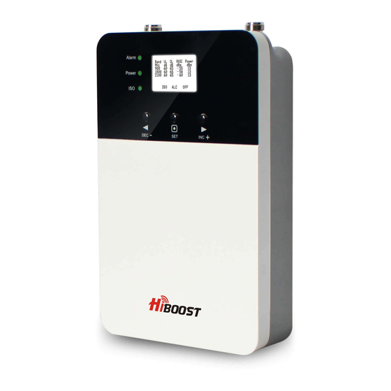
Page 7: Booster Ports' Description
independently, 31dB range. • Excellent RF performance, larger coverage area, clearer voice and higher data throughput. • Elegant design, compact size, very low power consumption to minimize cost during operation and low heat dissipation. • Inbuilt indoor antenna • Imbedded Bluetooth and Wi-Fi module for remote control via a mobile application Booster Ports’... -
Page 8: Control Button Operation And Manual Gain Control (Mgc)
lower than -10dBm, the value will display ”---”. ”ISO”- isolation alarm indication. When the booster doesn’t have enough isolation between the outdoor and indoor antennas, the “ISO” is flashing. Press the ”SET” key and the LCD screen will display ”ISO” value showing the current affected band or bands. Band UL DL RSSI Power ISO f l ash MHz dB dB dBm dBm... -
Page 9: Installing Hiboost Booster System
If none of the control keys are touched within 5 minutes, the LCD screen will turn off. Pressing any key will return the display to the fixed mode. Installing Hiboost Booster System Before You Install • Make sure you have sufficient cable length between the outdoor,indoor... -
Page 10: Installation Overview
Booster System Installation Examples 1 -Outdoor wide band directional antenna 2 -50ft (15.2m) Hiboost200 low-loss cable 3 -HiBoost booster with built-in antenna 1-Outdoor wide band directional antenna 2-50ft (15.2m) Hiboost200 low-loss cable 3-You can add an indoor panel/omni antenna and 50ft (15.2m) Hiboost200 low-loss cable to extend the... -
Page 11: Step 1. Install The Outdoor Antenna
Here are three methods can help find the strongest downlink signal from the local towers: 1. Use the LCD display on the HiBoost amplifier that shows the downlink output power on each band, We highly recommend to use this method as it is generally rather accurate. - Page 12 antenna on the roof of the building and point it to the nearest cell tower. Then have a look at the gain and output power values displayed on the LCD display. Band UL DL RSSI Power MHz dB dB dBm dBm 800 65 70 - 53 17 65 70 - 53...
- Page 13 1.2 Install the Outdoor Antenna Install the outdoor antenna in the location with the strongest received signal. IMPORTANT: Test the signal 3 times in the desired location before installing the outdoor antenna. It will help ensure the best booster performance. In most cases, the outdoor wide-band panel antenna is the best choice.
-
Page 14: Step 2. Install The Indoor Antenna
Note: Wrap waterproof tape around the connectors between outdoor antenna and feeder line to avoid water or other kind of damage. Step 2. Install the Indoor Antenna If you choose the product's built-in antenna to cover your place, no indoor antenna installation is required. -
Page 15: Step 4. Booster Commissioning
ISO status indicates if the booster has enough isolation between the outdoor and indoor antennas in order to avoid loop back or so-called self-oscillation. HiBoost is equipped with a smart AGC function to avoid interference with mobile networks. "ISO" flashing on the LCD display means that ISO function is working... - Page 16 Status Meaning Solution Methods No loop back or Remain still No action is needed. no self-oscillation. Flashing but actual gain is not Slight loop back No action is needed. more than 30dB or self-oscillation. status and less than rated gain. Flashing but Please check the Deep loop back...
- Page 17 More about LCD indication: Status Meaning Solution Methods Check coverage, leave it as it is if Output power is it's good; Please check the “---” status lower than Troubleshooting section -10dBm. to get solutions if coverage is not good. Severe loop “OFF”...
-
Page 18: Troubleshooting
Alarm LED: Indicates the strength of the received signal from the cell tower. Flashing Alarm means that the booster is receiving a strong signal on one or more bands. Alarm LED shall remain "Green" or "Slow Flashing Green". Slow flashing green indicates that everything is working well and the booster is working at nearly the optimum output power to achieve the best possible coverage. - Page 19 Eliminate flashing ISO legend and quick flashing green, quick flashing red ISO LED problems: 1. Adjust the outdoor antenna direction, keeping it away from the indoor antenna. Restart the booster. 2. Increase the vertical or horizontal distance between the outdoor antenna and indoor antenna.
-
Page 20: Main Specifications
Remark: • When increasing the downlink gain make sure the isolation is adequate to prevent system oscillation. Note: The flashing ISO and Alarm status indicates that ISO and ALC functions are working properly and the problems of self-oscillation and strong downlink signals are fixed. -
Page 21: Product Warranty
Hiboost signal boosters are covered with 2-year warranty. Huaptec offers two options for the products under warranty: repair or replace. This warranty does not apply to HiBoost signal boosters or kits that have been subjected to misuse, abuse, neglect or mishandling and that have its physical or electronic properties altered or damaged. -
Page 22: Huaptec Contact Details
5th FL, E BLDG, Sogood Benno-Strauß-Street 7, 6210 N. Belt Line Rd., Ste. Science Park, Hangkong 90763 Fürth, Germany 110, Irving, TX, 75063 Road, Xixiang, Bao'an, Shenzhen, China 518102 E-mail: E-mail: E-mail: tech@huaptec.com sales@huaptec.eu info@hiboostusa.com Website: Website: Website: www.huaptec.com www.hiboost.eu www.hiboost.com... - Page 24 Address: Benno-Strauß-Straße 790763 Fürth Phone:(44)20 3239 5802 E-mail : sales1@huaptec.eu Website : www.hiboost.eu Designed and Produced By Huaptec...
Need help?
Do you have a question about the Hi13- 3S and is the answer not in the manual?
Questions and answers