Table of Contents
Advertisement
IMPORTANT FOR FUTURE REFERENCE
Please complete this information and retain this manual
for the life of the equipment:
Model #: ___________________________
Serial #: ___________________________
Date Purchased: ____________________
Installation & Operation Manual
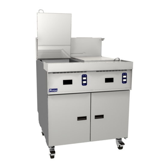
Model TB-SRTG
Floor Model Gas Rethermalizer
Model TB-SRTG-2 Shown
C
E
R
T
I
F
I
E D
I
220-376, rev. 2 (06/19)
Advertisement
Table of Contents

Related Manuals for Pitco TB-SRTG


Summary of Contents for Pitco TB-SRTG
- Page 1 Please complete this information and retain this manual for the life of the equipment: Model #: ___________________________ Serial #: ___________________________ Date Purchased: ____________________ Installation & Operation Manual Model TB-SRTG Floor Model Gas Rethermalizer Model TB-SRTG-2 Shown 220-376, rev. 2 (06/19)
- Page 2 Pitco and/or its Authorized Service and Parts (ASAP) WARNING companies, this warranty will be void. In addition, Pitco and its affiliates will not be liable for any claims, damages or Completely shut the appliance down when the water is being expenses incurred by the customer which arises directly or drained from the appliance.
-
Page 3: Table Of Contents
TABLE OF CONTENTS TB-SRTG: Gas Floor Model Rethermalizer 1. INSTALLATION ..................1 1.1. CHECKING YOUR NEW APPLIANCE ..................1 1.2. INSTALLATION CLEARANCES ....................2 1.3. LEG/CASTER INSTALLATION AND LEVELING ................2 1.4. PLUMBING CONNECTIONS ......................3 1.4.1. WATER INLET CONNECTIONS ..................... 3 1.4.2. - Page 4 TABLE OF CONTENTS 2.4.2. ADDITIONAL CONTROLLER FUNCTIONS ................. 17 2.5. COOKING ............................. 18 2.5.1. COOKING TIPS ........................18 2.6. APPLIANCE SHUTDOWN ......................18 2.6.1. STANDBY MODE ........................18 2.6.2. COMPLETE SHUTDOWN ....................18 3. PREVENTATIVE MAINTENANCE ............19 3.1. DAILY PREVENTATIVE MAINTENANCE ................... 19 3.1.1.
-
Page 5: Installation
INSTALLATION TB-SRTG: Gas Floor Model Rethermalizer 1. INSTALLATION 1.1. CHECKING YOUR NEW APPLIANCE Your new Pitco appliance has been carefully packed Accessories into one crate. Every effort has been made to ensure # Description TB-SRTG that it is delivered to you in perfect condition. As you... -
Page 6: Installation Clearances
INSTALLATION 1.2. INSTALLATION CLEARANCES The clearances shown below are for combustible and non-combustible installations and will allow for safe and proper operation of your appliance. Combustible Construction Non Combustible Construction Inches (centimeters) Inches (centimeters) Back 6.0" (15.24cm) 0.0" (0.0cm) Sides 6.0"... -
Page 7: Plumbing Connections
INSTALLATION TB-SRTG: Gas Floor Model Rethermalizer 1.4. PLUMBING CONNECTIONS The plumbing installation should be done by a licensed plumber and must comply with local and national codes. 1.4.1. WATER INLET CONNECTIONS If a faucet or water fill option is equipped on your appliance connections to a potable water supply will be required. -
Page 8: Gas Connection
INSTALLATION 1.5. GAS CONNECTION Your appliance will give you peak performance when the gas supply line is of sufficient size to provide the correct gas flow. The gas line must be installed to meet the local building codes or National Fuel Gas Code ANS Z223.1 and NFPA 54 (latest editions). -
Page 9: Ce Gas Table
INSTALLATION TB-SRTG: Gas Floor Model Rethermalizer 1.5.3. CE GAS TABLE Refer to the following table for gas specifications for the country of use. If the country of use is NOT listed, refer to the information stamped on the data plate. - Page 10 INSTALLATION CE Gas table Continued 14.4 14.7 50/37 25.4 LP16 14.4 14.4 14.7 25.4 LP16 14.4 14.4 14.7 50/37 25.4 LP16 14.4 14.7 25.4 LP16 14.4 2.58 mm N22/MF28 YES 14.7 25.4 LP16 14.4 14.4 14.7 25.4 LP16 14.4 14.7 25.4 LP16 14.4...
-
Page 11: Electrical Connections
INSTALLATION TB-SRTG: Gas Floor Model Rethermalizer 1.6. ELECTRICAL CONNECTIONS It is advised that this power supply be plugged into a wall receptacle that is controlled by the ventilation control. This will prevent the appliance from being operated without the ventilator on. If your appliance requires an electrical connection, the power requirements are listed below. -
Page 12: Ventilation And Fire Safety Systems
INSTALLATION WARNING If your appliance is uses line current, it is equipped with an oil proof, electrical supply cord with a three-prong safety plug. This is to protect operators from electrical shock hazard in the event of an equipment malfunction. DO NOT cut or remove the grounding (third) prong from this plug;... -
Page 13: Inspection
INSTALLATION TB-SRTG: Gas Floor Model Rethermalizer 1.8. INSPECTION Before you begin filling and adjusting the appliance, perform the following visual checks: After the appliance is in its permanent location, check the levelness. Any additional leveling that is necessary can be performed as previously described. -
Page 14: Initial Adjustments
INSTALLATION 1.9. INITIAL ADJUSTMENTS After your appliance has been properly installed as described in the installation section of this manual, it will need to be adjusted to ensure that it will perform as designed. A qualified person must perform these adjustments. To perform these adjustments the following tools will be needed: •... -
Page 15: Pilot Flame Adjustment
INSTALLATION TB-SRTG: Gas Floor Model Rethermalizer 1.9.3. PILOT FLAME ADJUSTMENT Perform this procedure with the pilot lit. Note: This procedure requires the use of a 1. Connect the DC microammeter between the flame sensor DC microammeter. terminal and the flame sensor lead. Observe proper polarity: if the meter needle goes below 0, reverse the leads. -
Page 16: Main Burner System Adjustment
5. When the pressure is correct, replace the regulator adjustment screw cover. Turn off the ALL appliances, shut the main gas valve to your Pitco appliance and remove the pressure gauge. Apply pipe joint compound to the manifold pressure tap plug and reinstall it. -
Page 17: Initial Cleaning
INSTALLATION TB-SRTG: Gas Floor Model Rethermalizer CAUTION Be careful not to disturb the probe and high temperature limit during operation and cleaning of this appliance. 1.10. INITIAL CLEANING When your appliance is shipped, many of its parts are covered with a thin coat of oil for protection. -
Page 18: Operation
OPERATION 2. OPERATION An operator’s manual for your appliance’s specific control type should be included with this manual. Refer to that manual prior to operating this appliance. 2.1. OPERATIONAL FEATURES The diagram below outlines some of the key operational components of your appliance. Refer to the following sections of this manual to learn more about these features. - Page 19 OPERATION TB-SRTG: Gas Floor Model Rethermalizer 1. Cook Tank 2. Controller (Not on all Models) Controls the water temperature inside the cook tank. Optional timers are located on the controller (if equipped). If the controller has an ON/OFF button, it will be used to turn ON the controller as well as other features on the appliance.
-
Page 20: Filling The Appliance
This appliance is not designed for cooking with oil. Fill with potable water only. Tank Capacity Model Capacity TB-SRTG 18.2 Gal. (68.9 Liters) 1. Ensure that the drain valve is closed. 2. Fill the tank with water until the water reaches the water level line(s). -
Page 21: Appliance Start Up
OPERATION TB-SRTG: Gas Floor Model Rethermalizer 2.3. APPLIANCE START UP Refer to the following procedure to start the appliance prior to operation. 1. Ensure that the drain valve is closed. 2. Fill the cook tank with water. (See section 2.1 “Filling the Appliance”) 3. -
Page 22: Cooking
OPERATION 2.5. COOKING It is important to keep the cook tank full of water to minimize the chance of boiling the appliance dry and to keep the water at a level that will provide optimum cooking performance. To ensure the quality of the food you cook in this appliance, follow the preparation instructions from the food manufacturer. -
Page 23: Preventative Maintenance
PREVENTATIVE MAINTENANCE TB-SRTG: Gas Floor Model Rethermalizer 3. PREVENTATIVE MAINTENANCE 3.1. DAILY PREVENTATIVE MAINTENANCE Performing the preventative maintenance steps below on a daily basis will keep your equipment safe and at peak performance. During the cooking process, starch build up will form on the temperature probes, tank and heating element. -
Page 24: Deliming
This section should ONLY be performed by a qualified service technician as part of a regular kitchen maintenance program. This inspection should take place a minimum of once a year by a Pitco Authorized Service Technician. It may be necessary perform this inspection more then once a year. -
Page 25: Ventilation Hood
PREVENTATIVE MAINTENANCE TB-SRTG: Gas Floor Model Rethermalizer Check incoming gas pressure when all gas appliances are on. Check ignition system and adjust pilot flame as required. Check flame sensor reading. Matchless Ignition: Check gap spacing and clean igniter. -
Page 26: Troubleshooting
TROUBLESHOOTING 4. TROUBLESHOOTING 4.1. POWER FAILURE If electric power is removed for any reason, the appliance will shut down. Wait five minutes after the power is restored before attempting to restart the appliance. This will allow time for any gas that may have accumulated in the burner or tubes to dissipate. -
Page 27: Troubleshooting Chart
TROUBLESHOOTING SRTG: Gas Floor Model Rethermalizer 4.4. TROUBLESHOOTING CHART Problem Probable Causes Corrective Actions No power to appliance. Check main building power supply. Circuit Breaker tripped. Reset circuit breaker. Controller does not Flip I/0 switch to I position and turn on I/0 Switch in 0 position. - Page 28 (603) 225-6684 World Wide representative (ASAP) covering your area, or Website Address: www.pitco.com contact Pitco at the numbers listed to the left. MAILING ADDRESS – P.O. BOX 501, CONCORD, NH 03302-0501 SHIPPING ADDRESS – 39 Sheep Davis Road, Pembroke, NH 03275...
Need help?
Do you have a question about the TB-SRTG and is the answer not in the manual?
Questions and answers