
Related Manuals for Flowserve PMV F5 Series


Summary of Contents for Flowserve PMV F5 Series
- Page 1 Manual F5 Manual F5 Logix 510si Digital Positi PMV Valve Control System PMV Valve Control System alve Control System Manual F5 – 1 – alve Control System Manual F5 – 1 –...
- Page 2 Manufacturers declaration • Hersteller-Erklärung • Déclaration de fabricant Manufacturers declaration We hereby confirm that the appliances described in this sheet has been manufactured in compliance with the applicable standards and is intended for installation in a machine/application, and that commissioning is strictly prohibited until evidence has been provided that the machine/application in question is also in compliance with EC directive 2006/42/EC, 2006/95/EC and 2004/108/EC.
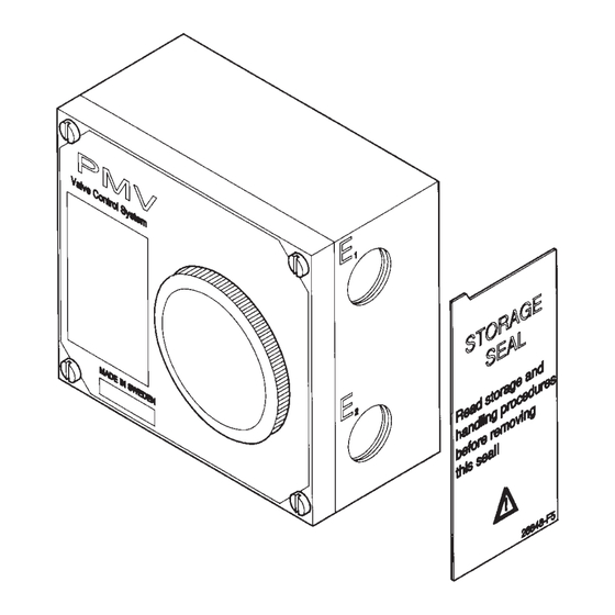
- Page 3 PMV Feedback module storage and handling procedures PMV feedback modules are precision instruments which should be stored and handled accordingly to avoid problems or damage. Feedback modules contain electronic components which can be damaged by exposure to water. Appropriate precautions should be taken to protect units while in storage.
- Page 4 Description The PMV F5 is a feedback unit uniquely designed to mount on top of the PMV P5, EP5 or P-2000 positioners with minimum parts required. The F5 can also be mounted on actuators with an additional mounting kit. The F5 is available in two different enclosures, standard or explosion proof.
-
Page 5: Product Label
Product label F5 IS Intrinsically safe F5 EX Explosion proof Manual F5 – 5 –... - Page 6 odell code Manual F5 – 6 –...
- Page 7 Mounting on P5 or EP5 – See www.pmv.nu/downloads for video clip. – Remove the front cover and the indicator from the positioner. – Loosen and remove the Allen head screw (3) (5mm hex-wrench) – Install drive coupling (4) on the positioner shaft, secure it with screw (3) –...
- Page 8 Mounting on P-2000/P-2020 – Remove front cover, indicator and cam nut from the positioner – Replace the cam nut with coupling 1, calibrate the positioner. – Check that the gasket is fitted to the bottom of plate 2, install screws 5 (3x long, 1x short) plastic washer 6 and O-rings 7.
- Page 9 F5-EX The F5-EX is approved explosion proof by CSA, FM and ATEX. Front cover screws shall be tightened 7 Nm (5,2 lbf x ft). Approvals: CSA, FM Div. 1, Class 1,2 & 3 Group BCDEFG T4-T6 ATEX II 2 G EEx d IIB + H2 T4-T6 Manual F5 –...
- Page 10 Installing F5-EX on P5/EP5 – See www.pmv.nu/downloads for video clip. – Remove front cover, indicator and Allen head screw from the positioner. – Install drive coupling 4 and secure it with the Allen head screw. – Remove front covers and indicator from the F5-EX unit. –...
- Page 11 Connections WARNING! Units installed in hazardous locations must have proper agency approvals and be installed according to installation drawing F5-2-4-9516. Conduit entries are PG13,5 (M20) or NPT 1/2“ Make electrical connections according to wiring diagrams and tighten cable glands. Terminals are 2.5 mm (AVG 14) screw terminals.
- Page 12 Calibration 4-20 mA position transmitter Instruction video available on www.pmv.nu/downloads 1. Set direction of rotation by placing potentiometer jumper in location A or B. (Location A for counter clockwise CCW valve/actuator rotation (Direct), location B for clockwise CW valve/actuator rotation (Reverse). 2.
- Page 13 Potentiometer only (no transmitter function) 1. Make electrical connections to terminals 7,8 and 9. Check that the potentiometer is connected to connector C on the printed circuit board. 2. Stroke the actuator to check direction of travel indicated by the potentio- meter.
- Page 14 Connection of F5 intrinsically safe version Manual F5 – 1 –...
- Page 15 F5 IS Manual F5 – 15 –...
- Page 16 F5 IS Manual F5 – 1 –...
- Page 17 F5 IS Manual F5 – 1 –...
- Page 18 F5-EX Manual F5 – 1 –...
- Page 19 F5-EX Manual F5 – 1 –...
-
Page 20: Spare Parts
Spare Parts 10-13 10-13 10-13 Manual F5 – –... -
Page 21: Spare Parts List
Spare Parts List Manual F5 – –... -
Page 22: Dimension Drawing
Dimension drawing Manual F5 – 2 –... -
Page 24: Troubleshooting
Palmstierna International AB Korta Gatan 9 SE-171 54 Solna SWEDEN Tel: +46 (0) 8 555 106 00 Fax: +46 (0) 8 555 106 01 E-mail: infopmv@flowserve.com Internet: www.pmv.nu SUBSIDIARIES: Flowserve Flowserve Abex Road Postfach 2310...
Need help?
Do you have a question about the PMV F5 Series and is the answer not in the manual?
Questions and answers